CHAPTER ^
Microdetermination of Carbon and Hydrogen
Since all organic compounds contain carbon, the determination of carbon and hydrogen is the most frequently performed analysis and, therefore, should be considered to be the most important. It also requires the greatest skill and the most exacting of conditions. The determination has been* the subject of much discussion in the past and collaborative studies have been conducted with the hope that from these a more foolproof method will be developed.3 8 3'3 8 4 In the opinion of the author, the beginner will be successful with this determination, almost from the beginning, if his laboratory conditions are controlled (see Chapter 1 ) and if he closely adheres to the directions given in the following pages. It should be understood, however, that few persons achieve acceptable results on their first few tries.
Beginners should not attempt to use some modifications of their own.
It is true that out of a group of experienced microanalysts, probably no two will perform the determination in exactly the same manner. However, each variation has resulted from years of experience.
The organic compound is burned at red heat in an atmosphere of oxygen and the carbon and hydrogen are converted into carbon dioxide and water respectively as shown by the following:
Δ Organic C - » C 02
o
2Δ Organic Η - » H20
The water is absorbed by magnesium perchlorate (Anhydrone3 5 7 or Dehy- d r i t e3 5 7) and the carbon dioxide is absorbed by sodium hydroxide on asbestos ( A s c a r i t e3 5 7) .
Generally, the combustion tube contains sections of the following materials in the order named, starting at the capillary tip: silver, lead peroxide, silver, a mixture of copper oxide and lead chromate, platinum, and finally silver.
The sections of silver remove chlorine, bromine, iodine, and oxides of sul-
* See Additional Information, pp. 2 5 5 - 2 6 4 . 221
£ ^ 5 4, 1 1 2, 1 1 3 , 1 4 6 , 2 8 4 , 2 8 5 , 2 8 8 , 3 0 8 , 3 1 7 - 3 2 0 , 3 5 0 The platinum assists in the combustion of condensed ring systems, particularly those containing an angular methyl group which might come off in the form of methane and escape complete combus
t i o n .2 8 5 The copper oxide-lead c h r o m a t e1 1 2'1 1 3'2 8 4'3 0 8'3 1 7-3 2 0'3 5 0 mixture acts as an oxidizing agent. The lead peroxide reacts with and retains oxides of nitrogen which is represented by the following e q u a t i o n s17 4 , 1 7 5 , 2 8 5 , 3 0 5 .
2NO + 2 P b 02 - » P b ( N 02)2. P b O + i /202
2 N 02 + 2 P b 02 P b ( N 03)2 + PbO + i /202
When fluoro-compounds are being analyzed, either of the two following slight modifications in the tube filling is necessary so that fluorine is prevented from passing through:
(a) Two small sections of magnesium oxide are substituted for a portion of the copper oxide-lead chromate mixture,3 4 8 or
( b ) A section of aluminum oxide is added between the copper oxide- lead chromate mixture and the platinum.3 3 8-3 4 8
Although both modifications have proven satisfactory, the author prefers the use of the two sections of magnesium oxide, particularly with compounds also having a high sulfur content. (When fluoro-compounds are analyzed only occa
sionally, the ordinary tube filling, without the added aluminum or magnesium oxide, may be used provided the sample is covered with magnesium o x i d e .3 3 8 , 3 4 8
This, however, usually gives slightly higher results than when the oxides are in the filling, which is to be expected.)
Compounds containing arsenic, antimony, bismuth, and mercury should not be analyzed unless further modifications in the procedure (see Additional Information for this chapter) are made since these elements would ruin the combustion tube filling. 1 0 3 , 1 1 2 , 3 1 7 - 3 2 0 , 3 5 0 However, they can be successfully analyzed for carbon by the Van Slyke manometric m e t h o d3 6 7'3 6 8 described in Chapter 18. ( Y e h3 8 8 a has obtained excellent results with fluoro-, arsenic, antimony, tin, mercury, and selenium compounds using a special tube filling composed of silver vanadate, zirconium oxide, and magnesium oxide. ) Compounds containing the alkali or alkaline earth metals in the absence of sulfur or phosphorus under the conditions of the determination would leave an ash of the carbonate, and the r e s u l t1 1 2'3 1 7-3 2 0-3 5 0 would be lacking the percentage of one carbon atom.
Therefore, potassium d i c h r o m a t e1 1 2-3 1 7-3 2 0'3 5 0 or vanadium pentoxide is added to the sample and during the combustion all of the carbon is con
verted to carbon dioxide. If, however, enough sulfur or phosphorus is present in the compound to react with the alkali or alkaline earth metal to form the sulfate or phosphate, respectively, no dichromate or vanadium pent
oxide need be a d d e d .3 4 8 , 3 5 0 I f halogens are present in sufficient amounts to
223 Reagents
form the halides, it should not be necessary to add dichromate or vanadium pentoxide, but in spite of this, the author prefers the addition.3 4 8
Silver salts, aurates, and platinates give correct results and, in addition, weighing of the residue gives the amount of precious metal (as free metal—
compare Chapter 6 ) . Similarly, salts of copper and iron leave as an ash the oxide (see Chapter 6 ) and offer no interference.
Substances containing phosphorus in the absence of alkali or alkaline earth metals leave an ash of oxides of p h o s p h o r u s2 6 2'3 4 8 , 3 5 0 which holds onto small amounts of carbon and must be ignited strongly or low values result.
Reagents
All reagents listed here are commercially available and can be used without further treatment.
SODIUM HYDROXIDE SOLUTION
About 1 liter of a solution of sodium hydroxide ( 5 % ) in water is required for the pressure regulators.
CONCENTRATED SULFURIC ACID
About 1 ml. of concentrated sulfuric acid is required for the bubble counter (Fig. 1 2 0 ) .
ANHYDRONE™7 OR DEHYDRITE357 (MAGNESIUM PERCHLORATE)
This material is used in the following pieces for the purpose of absorbing water: U-tube (Fig. 1 2 0 ) , both absorption tubes (Fig. 1 2 7 ) , and guard tube
(Fig. 1 2 8 ) .
Neither large pieces nor fine powder should be used—otherwise no special selection of size is necessary.
ASCARITE*57 (SODIUM HYDROXIDE ON ASBESTOS)
The commercially available material of size 8 - 2 0 mesh is used in the U-tube (Fig. 1 2 0 ) and in the carbon dioxide absorption tube (Fig. 1 2 7 ) .
SILVER WIRE (OR RIBBON)
Fine silver wire (or ribbon) of approximately 34 gauge is used in the combustion tube.
ASBESTOS
Ordinary acid-washed Gooch crucible asbestos is used without further treatment.
POTASSIUM DICHROMATE
Reagent grade is melted in a crucible by heating at 400° C1 1 2-1 2 8-3 1 7"3 2 0'3 5 0 The melt is cooled, powdered, and dried in an oven at 120° C. for a short while.
It is stored in a glass-stoppered bottle.
PLATINIZED ASBESTOS, 3 0 %9'8 7'3 5 7
This material is used in the combustion tube.
COPPER OXIDE WIRE
Ordinary reagent grade of cupric oxide wire is used. No special screening is necessary but neither large pieces nor fine powder should be used (about 1-2 mm. lengths are quite suitable).
LEAD CHROMATE
Special lead chromate for microanalysis is commercially a v a i l a b l e8 7'2 6 3'3 5 7 and should be used.
COPPER OXIDE-LEAD CHROMATE MIXTURE
This mixture is made of two parts of copper oxide and one part of lead chromate (by weight) and thoroughly m i x e d .1 1 2'2 8 4'3 0 8'3 1 7"3 2 0'3 5 0
LEAD PEROXIDE (LEAD DIOXIDE)
Special grades for microanalysis are commercially a v a i l a b l e8 7'2 6 3'2 8 2'3 5 7 and should be used since they require no further treatment. Otherwise they must be p u r i f i e d .1 1 2'2 8 5'3 1 7-3 2 0
VANADIUM PENTOXIDE
Reagent grade is used for the same purpose as the potassium dichromate.3 4 8
ALUMINUM OXIDE
Reagent grade of aluminum oxide (granular) is used in the combustion tube for determinations on fluoro-compounds.338'348
MAGNESIUM OXIDE348
Reagent grade of precipitated magnesium oxide. This is used either in the combustion tube or on the sample when fluoro-compounds are being analyzed.
It must be free from moisture and carbonate.
MAGNESIUM OXIDE-ASBESTOS348
Equal parts by weight of the magnesium oxide and the asbestos are thoroughly mixed by shaking in a closed bottle. This is used in the combustion tube when dealing with fluoro-compounds.
225 Apparatus
ABSORBENT COTTON
Ordinary sterile absorbent cotton is used in the absorption tubes.
FIBERGLASM
This material is used to hold the Anhydrone and Ascarite in place in the U-tube.
KROENIG GLASS CEMENT87 3 5 7
All ground joints are held together with this material. It is prepared from one part white beeswax and four parts of rosin and is commercially available in stick form. It is warmed before using and the parts held in place until the wax sets.
Apparatus
The apparatus consists of a cylinder of oxygen having a reducing valve, a supply of compressed air to which a filter system is attached, two pressure regulators, one each for oxygen and air, one bubble counter-U-tube, one combustion tube, one combustion apparatus, one heating mortar, two absorp
tion tubes, one guard tube, one Mariotte bottle, one graduate cylinder, and two types of rubber tubing. With the exception of the pressure r e g u l a t o r s ,1 0 6 , 3 5 0
all of the glass parts are those for which recommended specifications have been published by the Committee for the Standardization of Microchemical Apparatus of the Division of Analytical Chemistry of the American Chemical Society.3 5 1
OXYGEN CYLINDER
A small cylinder of pure oxygen having some sort of reducing valve is required.
Any convenient size ranging from the small lecture bottle to the large size may be used. The oxygen should be prepared from liquid air rather than by elec
trolysis of water since the latter type might contain traces of hydrogen.
COMPRESSED AIR SUPPLY
The ordinary laboratory supply of compressed air may be used but must be filtered through a section of cotton to remove dust, oil, and water. A con
venient filter is made by filling a Mariotte bottle* (see below) with cotton.
Since the compressed air is very slowly taken from the line, very little oil or water is removed and a filter will last for years without needing replacement.
PRESSURE REGULATORS1™'650
By means of the pressure regulators, oxygen and air are supplied to the com
bustion train at constant pressure. Two regulators are required, one for each
* Only the bottle is used—not the other parts. Air is led in at the bottom on the side and is taken out at the top.
of the above gases. Each regulator consists of two essential parts: the pressure regulator proper and a leveling tube for obtaining the desired height, con
nected by means of rubber tubing as shown in Fig. 118. The two regulators
FIG. 1 1 8 . Pressure regulators—photograph showing connections.
are connected by means of a T- or Y-tube, which in turn is connected to the bubble counter of the combustion train. (See diagram of combustion train—
Fig. 1 3 0 . ) Five per cent solution of sodium hydroxide is used in the regulators.
Figure 119 shows the details of construction of the unit: a is the leveling tube and b the regulator proper; c is the inlet tube which is connected to the
227 Apparatus
FIG. 119. Pressure regulator—details of construction.
source of oxygen or air. The gas passes vertically down through it, coming out at outlet e and displacing the solution between the vertical part of c and the jacket, d. When the space between c and d is completely filled, the excess gas overflows at / and passes up through the solution and out into the air through h. The position of e should be such that the gas bubbles strike the notch, f. (If, on testing a regulator, it is found that the outlet has been improperly placed, the condition may be corrected by applying the flame of a small blast lamp at point g. When the glass has softened slightly at g, that section of the tube between g and e is allowed to fall into place by gravity.) The height at which the solution stands in b is shown on the graduated scale, this also being the pressure head maintained in d. The gas under the desired pressure passes out through the stopcock and tube i to the bubble counter and the combustion tube.
BUBBLE COUNTER-U-TUBE3™™1
The bubble counter portion is used as an indicator for determining the rate of flow of oxygen and of air through the system while the U-tube part removes water and carbon dioxide from these gases before they enter the combustion tube. The details of construction are shown in Fig. 120. The gas enters the bubble counter on the left from the pressure regulators (see Fig. 130, diagram of combustion t r a i n ) * and passes downward through the inner bulb which contains enough concentrated sulfuric acid to immerse the lower 5-7 mm. of the tip of the capillary. The gas then passes through the U-tube into the com
bustion tube.
FILLING T H E B U B B L E C O U N T E R - U - T U B E.1 1 2'1 1 3'2 8 4-2 8 5'3 0 8'3 1 7-3 2 0-3 5 0 Enough Ascarite is placed in the U-tube through the glass ground joints so that the bottom is filled and the absorbent stands at the height of about 6 - 7 cm. on the right side* (next to the combustion tube) and about 3 - 4 cm. on the left side* (next to the bubble counter). Small layers ( 2 - 3 mm.) of Fiberglasf are put on top of the Ascarite to hold it in place. Enough Anhydrone is then added through each ground joint so that it comes to within 1-2 mm. below the horizontal connecting tubes. (During the addition of both Ascarite and Anhydrone, care must be exercised so that neither material enters the bulb of the bubble counter.) Enough Fiberglas is added to each side to fill the remaining spaces up to the bottoms of the glass stoppers. The ground joints and stoppers are warmed gently with a burner and a film of Kroenig glass cement is applied. The stoppers are put in place and the cement allowed to cool. With the aid of a medicine dropper, enough concentrated sulfuric acid
* In Fig. 130, the direction is reversed.
t Cotton should not be used in the bubble counter-U-tube because of the possibility of perchloric acid ( M g ( C 1 04)2 + H2S 04) accidentally coming in contact with organic material resulting in an explosion.
Ï9 SOLID STOPPERS 5+0.5MM. O.O. WALL I MM. APPROX. 50-55MM —3-4 MM. 0.0. 12 TO 1.5 MM, LDl GROUND AND BEVELED END TO BE 2-3 MM. FROM BOTTOM OF BULB 18-20 MM. 5±0. 1.5-2
h
5 MM. 0.0 1M. LO. z---^LAZED -80-90 MM. 105-110 MM. U-I3±0.5MM. O.D. ^WALL 1.25 MM. APPROX. FIG. 120. Bubble counter-U-tube—details of construction.229 Apparatus
is added, through the horizontal tube on the left, so that the bulb contains enough to immerse the lower 5-7 mm. of the tip of the vertical capillary.
The bubble counter-U-tube can be used until the Anhydrone on the side of the bubble counter appears to be wet. Usually this condition exists after about 7 5 - 1 0 0 determinations. The apparatus is then cleaned out by washing with water and refilled.
THE COMBUSTION
TUBE
1 0 , 3 5 0'
3 5 1The combustion tube should have the dimensions shown in Fig. 1 2 1 . Tubes prepared from thinner stock have been shown to be less reliable. Tubes may be prepared of Pyrex No. 1720 glass,6 4 Jena Supermax,3 3 7-3 5 7 the British hard glass,3 5 7 Vycor6 4 ( 9 6 % silica glass No. 7 9 0 ) , or of quartz. (Listed in the order of increasing temperature of softening point.) The author prefers tubes made of Pyrex No. 1720 as these have proved most satisfactory in his laboratory.3 4 9 Under the conditions of use described in the following pages, one of these tubes will give good results for about 300 determinations, on the average. (Occasionally, a tube will be good for 500 while others are dis
carded after 100.)
FILLING T H E COMBUSTION Τ υ Β Ε .1 1 2-1 1 3-2 8 4·3 0 8-3 1 7 - 3 2 0-3 5 0— ( S e e Fig. 1 2 2 . ) (A) Regular Filling. [Note: When used for fluoro-compounds, magnesium oxide must be added to the sample3 3 8-3 4 8—see Procedure. However, when fluoro-com
pounds are being analyzed, it is preferable to use the modified fillings described below under ( B ) or ( C ) ] . Considerable care must be exercised in the filling of the tubes. The combustible gases passing through it must come in contact with very large surfaces of the various components, but the packing must be loose enough so that the recommended gas velocities may be maintained using limited pressure heads. Fortunately, a rather large variation is possible. The pressure regulator can furnish gas under a constant pressure of from 0.1 to 15.0 cm.
of sodium hydroxide solution (see above). The recommended pressure head for bubble counter-U-tube and combustion tube together is between 5 and 15 cm., although tubes have been known to give good results with a pressure head of even less than the lower figure. The tube is so packed that when in use with the above conditions 10 ml. of gas pass through it per minute. Other speeds ranging from 3 to 50 or more have been u s e d2 7-1 0 4'1 1 2'2 8 4'2 8 5'3 0 8-3 1 7-3 2 0'
3 5 0 , 3 8 5 D U{ - tn e author recommends the above for the beginner. After he has mastered the technique at 10 ml. per minute he may increase the speed slightly, preferably to 12 ml. per minute.
The technique of filling the C-H combustion tube is quite different from that employed for preparing the Dumas one. With the latter, the components could be packed tightly, because C 02 under a pressure head of about 3 7 - 4 0 cm. of water is used, several times that which is obtainable with the carbon- hydrogen pressure regulator.
520-530 MM. 90+5° 5to.5 MM. O.D. 1.5-2 MM. 1.0.
2 1
-30- 35 J MM. 1 2-3 MM.—j \ MM. END SQUARED AND GLAZED
f 11.25*0.5 MM. O.D. 8t 0.25 MM. I.D. 1.5 MM. MIN. WALL
END SQUARED AND GLAZED 3.251 0.25 MM. O.D. 1.5-2 MM. 1.0, FIG. 121. Combustion tube with tip and side arm—details of construction.
231 Apparatus
/
<«0 9 7>if/ /
FOR ALTERNATES "THIS SECTION - SEE BftC SAMPLE BOAT HEATING MORTAR 1 COVERS THIS SECTIONN LONG STATIONARY FURNACE COVERS THIS SECTION -10 mm. SPACESHORT MOVABLE SAMPLE FURNACE COVERS THIS SECTION TUBE A. Ο*1 J"p Ο 0)'
i? I / Il /j TUBE B. TUBE C. NOTE: REMAINDER OF TUBES BSC SAME AS A. WITH EXCEPTIONS SHOWN. FIG. 122. Carbon-hydrogen combustion tube fillings.
233 Apparatus
The inside of the tube is wiped free from dust with a cotton swab on the end of a piece of rigid wire whose end is knurled. The author does not believe that elaborate cleaning of the tube or treatment or handling of the components of the filling is necessary, as recommended in the p a s t ,1 1 2'2 8 4'2 8 5'3 0 8 , 3 1 7 - 3 2 0 be
cause any organic material present is destroyed during the burning out process (see below).
Two or three strands of silver wire (or ribbon) about 100 mm. long are twisted together and inserted in the capillary tip of combustion tube so that the wire is flush with the end and extends well into the main body portion (11 mm. O . D . ) . Enough silver wire (or ribbon) is then rolled together to form a wad about 10 mm. in length and whose diameter is approximately that of the I.D. of the combustion tube. This is forced into the tube and all the way down to the tip while the twisted strands are prevented from being pushed out. In this way the wire passing through the capillary tip is locked securely in place. I f a portion protrudes past the end of the tip it should be cut off flush with the end, using scissors. The function of the silver at this end and in the tip is to conduct heat so that water will not condense during the combustion.
A section of asbestos of 3-7 mm. is next added by gently compressing
with a glass rod. This is called the choking plug112>284,285,308,317-320,350 an d offers resistance to the flow of the gases. It must be kept in mind during prepara
tion that the asbestos expands when heated and gives the effect of a tighter packing.
Enough lead peroxide is added, with gentle tapping of the side of the tube to secure good packing, to form a section about 33 mm. in length. The exact length of the lead peroxide portion will depend upon the size of the heating mortar used as most of the portion of the tube in it contains this material. The inside wall of the tube is wiped clean by means of a cotton swab. Another plug of asbestos, about 4 mm. in length, is gently pushed into place and this is followed by a section of silver wire, which has been rolled together to form a wad, about 40 mm. long. When the tube is inserted in the furnace this section should extend 1 cm. into the tube portion in the heating mortar, bridge the gap between this and the long furnace and extend at least 1 cm. into the hot portion of the latter (Figs. 122, and 1 3 0 ) . This silver wad acts chiefly as a conductor of heat between the two and prevents condensation of water.
A small section of asbestos {about 2-3 mm.) is added with gentle pressure.
At this point, it is advisable to make certain that the filling is not too tight.
This can be done by attaching the capillary tip to the Mariotte bottle. With the drainage tube of the latter depressed about 2 0 ° - 3 0 ° below the horizontal, gas should be sucked through at the rate of about 3 0 - 4 0 ml. per minute.
Enough of a mixture of copper oxide and lead chromate (2 parts CuO.l
part PbCr04) is added, with gentle tapping on the side of the tube to insure even packing, to form a section 140 mm. in length. This is held in place with about 2 mm. of asbestos. The inside wall of the tube is cleaned with a cotton swab. Enough platinized asbestos is added to form a very loose, but evenly packed, section about 10-15 mm,, in length. This material is quite fine and if it is more than gently compressed, too much resistance will be offered at this point.
The final portion of the tube filling is silver wire (or ribbon) rolled together to form a section about 40 mm. in length. When the tube is in the combustion apparatus, this should extend beyond the end of the long furnace about 1 0 - 1 5 mm. for the purpose of conducting heat, when the two furnaces are in contact.
The silver at this point is nearest to the sample and it is here that the chlorine, bromine, iodine, and oxides of sulfur are t r a p p e d .1 4 6-3 5 0 The filled combustion tube is then stoppered with a clean well-rolled cork and is ready to be con
nected with the other members of the combustion train. When the tube is heated to 680° C , the contents expand and the filling becomes more com
pressed. This must be kept in mind so that the filled tube, in use (at the above temperature and connected to the bubble counter-U-tube), will allow
10 ml. of air or oxygen per minute to pass through it when supplied at a pressure equal to 5-15 cm. of 5 % sodium hydroxide solution.
(B) Filling for Fluoro-Compounds 3 4 8 The filling is done as described under (A) Regular Filling, except that two sections of 10 mm. each of the mixture of magnesium oxide* and asbestos ( 5 0 % each by weight) replace part of the copper oxide-lead chromate mixture as shown in Fig. 122 B . After the silver wire, choking plug, lead peroxide, silver wire (ribbon) between the heating mortar and long furnace, and 2 - 3 mm. of asbestos are in place (in the order named) only enough of the mixture of copper oxide and lead chromate is added to form a section 30 mm. in length. This is held in place by about y2 m m- of asbestos and then enough of the magnesium oxide and asbestos mixture is added to form a very loose, but evenly packed, section of about 9-10 mm. in length. This is held in place by about !/2 mm. of asbestos and then another section of evenly packed copper oxide-lead chromate mixture about 90 mm. in length is added, followed by another section of the magnesium oxide-asbestos mixture about 9—10 mm. in length. (The total length of the copper oxide-lead chromate and magnesium oxide sections, four in all, should be 140 mm., or the exact length of the copper oxide-lead chromate mixture present in the regular filling described above.) Enough platinized asbestos is added to form the very loose section about 10-15 mm. in length as described under (A) Regular Filling, followed by the final section of silver wire, about
* Magnesium aluminate has been used for the retention of fluorine by some w o r k e r s .3 2 4
235 Apparatus
40 mm. in length. Extreme care should be exercised in the filling of this modifi
cation as there is a distinct tendency towards packing the tube too tightly.
( C ) Alternate Filling for Fluoro-Compounds.33S>S48 The modification described under ( B ) , above, is preferred by the author, particularly when large amounts of sulfur also are present, but the following one has been used successfully on a large variety of compounds. The tube is filled as described under (A) Regular Filling except that only 130 mm. of the copper oxide-lead chromate mixture is used, followed by enough granular aluminum oxide* (with an occasional interspersed shred of asbestos to prevent packing too tightly) to form a very loose, but evenly packed, section about 10 mm. in length. The filling is com
pleted by the addition of the regular amounts of platinized asbestos and silver wire (or ribbon) (see Fig. 122 C ) .
COMBUSTION APPARATUS
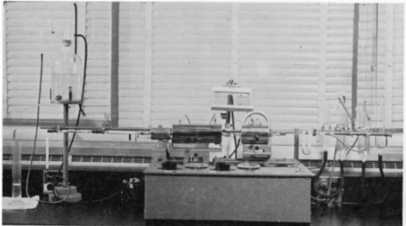
The combustion apparatus used for the determination of carbon and hydrogen should be e l e c t r i c a l l y8'5 9'1^ heated and the voltage supplied to the furnace should be quite c o n s t a n t .2 8 5'3 4 8»3 5 0 I f the regular
FIG. 123. Photograph of carbon-hydrogen apparatus, custom made, author's laboratory.
line voltage in the laboratory varies more than about 2 volts per day, a voltage regulator of some type such as a constant-voltage transformer should be used (refer to Chapter 1 ) . A large percentage of the units in use in the various large laboratories have been constructed in their respective machine s h o p s .8'5 9'2 1 2'3 8 5 Figure 123 shows a photograph of a suitable apparatus, one of those used by the author. This combustion apparatus consists of a long furnace and a power-driven short or sample furnace (see footnote, p. 154, Chapter 7 ) . The
* Magnesium aluminate has been used for the retention of fluorine by some workers.3 2 4
furnaces are composed of nichrome wire windings in asbestos blocks* and are of the split type that can be pushed back away from the combustion tube.
The long furnace is 205 mm. in length and can accommodate combustion tubes whose outside diameters are up to 13 mm. The short furnace also accommodates this size tube and is 110 mm. in length. The windings of each are of such resistance, that when operated through a variable auto-transformer, the desired operating temperature of 680° C , in the combustion tube, may be attained.
The short furnace travels at the rate of approximately 7 mm. per minute and can travel 7 5 - 1 0 0 mm. The furnaces used by the author for the carbon- hydrogen determination are the same as those used for the Dumas nitrogen method. Safety shieldsf are attached to the furnaces in the vicinity of where the sample is placed, for the protection of the analyst.
FIG. 124. Sargent combustion apparatus.
At this writing, no American Society for Testing Materials specifications have been adopted for furnaces to be used for the microdetermination of carbon and hydrogen, but such are in preparation and are expected to be similar to those for the Dumas nitrogen (see Chapter 7 ) .
Several types of f u r n a c e s4 5'8 7'1 2 9'3 2 8 , 3 5 7 are commercially available, some of which are mechanized while some are not. It is the opinion of the author as well as o t h e r s8'5 9'1 0 4'1 1 6'3 2 2'3 4 9-3 5 0'3 8 2-3 8 5 that the former should be used.
Figures 124 and 125 show two of the commercially available combustion apparatuses, with attached heating mortars (see below). Both are mechanized and have wide ranges of operating temperatures, making them suitable for the various combustion methods. (Also see Additional Information in regard to a new automatic apparatus.6 1 5 1)
* Available from C. and H. Menzer Co., Inc., 105 Barclay Street, New York, f Stanley No. 600 shields, Stanley, New Britain, Connecticut.
HEATING Μ Ο Κ Τ Α β1 1 2 , 1 1 3 , 2 8 4 , 2 8 5 , 3 0 8 , 3 1 7 - 3 2 0 , 3 5 0
The heating mortar can be considered to be almost part of the combustion furnace. It maintains the lead peroxide portion of the tube at a constant temperature, usually to within 1° C , somewhere in the range of 1 7 5 ° - 1 9 0 ° C.
Electric heating mortars are commercially available and are of two types:
( 1 ) those using thermostatic c o n t r o l8 7-3 2 8'3 5 7 and those which are controlled by maintaining constant current.1 2 9 Both types are quite satisfactory. They may be purchased either as part of the combustion apparatus or separately. Figures 123, 124, and 125 show types of heating mortars attached to combustion fur
naces and Fig. 126 shows a separate unit.
FIG. 126. Heating mortar.
Electric heating mortars are approximately 80 mm. in length and the open
ing through which the combustion tube is inserted is approximately 14 mm., which insures a close, but safe, fit with the latter. Attached to the heating mortar is a small metal hook which can be rotated to make contact with the capillary opening of the water absorption tube, when attached, thereby pre
venting condensation at this point.
The heating mortar is mounted next to the long furnace of the combustion apparatus, usually 3 - 1 0 mm. of space separating the two parts.
ABSORPTION TUBES'660'351
Two absorption tubes (Fig. 1 2 7 ) are required for the determination—one for water and the other for carbon dioxide. They should be made from soda-lime glass in order to reduce accumulation of electrostatic charges. There are two standard lengths and the longer is recommended, if the balance can accommo
date it, as more determinations can be done per tube. When Anhydrone and Ascarite are used for absorbing the water and carbon dioxide, respectively, the Ascarite tube clearly shows the extent to which it is exhausted, but the Anhydrone does not until it becomes actually wet at the end. The tubes should be used as a unit and when the Ascarite tube indicates time for cleaning and refilling, the same should be done to the Anhydrone tube. If, however, an
239 Apparatus
accident occurs and one tube is broken long before refilling is indicated, only the one need be replaced. Tubes give good results until the Ascarite tube shows sodium carbonate (lighter in color than the Ascarite and appears to be somewhat fused) to within about 5 - 1 0 mm. of the end. (For tube fillings compare Fig. 1 3 0 . )
(a) T H E W A T E R T U B E. Enough absorbent cotton is forced into the bottom of the absorption tube with the aid of a glass rod, to form a section 4 - 5 mm.
in length. This prevents Anhydrone from passing through the opening. The cotton wad is followed by about 10 mm. of Anhydrone and then another sec
tion of cotton, 2 - 3 mm. long. Anhydrone is then added, with tapping to
C R I T I C A L 3 . 2 5 * 0 . 2 5
M M . 0 . 0 . G L A Z E D .
0 . 2 5 Î . 0 5 M M . I . D . 5 M M . L E N G T H
1 2 M M . M A X . 0 . D .
_J
0 . 2 5 * 0 . 0 5 M M . I . D . 4 - 5 M M . L E N G T H
M M . I . D .
8 - 9 M M . I . D .
W A L L T H I C K N E S S Γ 0 . 5 5 Μ Μ . Ϊ 0 . Ι 0 Μ Μ .
- 0 . 4 0 + 0 . 1 0 m O P E N I N G S
- 3 8 - 4 2 M M . - C R I T I C A L 3 . 2 5 * 0 . 2 5 M M . 1 0 . D
G L A Z E D
2 . 2 5 Î 0 . 2 5
M M . I . D .
FIG. 1 2 7 . Absorption tube—details of construction. No markings or etchings on outside.
Approx. length Over-all length Length of
for absorbent with stopper body (mm.) (mm.) (mm.)
Size A B C
1 8 0 1 7 0 ± 5 1 3 5 ± 5 2 1 0 0 1 9 0 ± 5 1 5 5 ± 5
insure even packing, to within 3-5 mm. of the ground joint. (Better packing is obtained if the material is introduced up to the joint, a wad of cotton added, and the tube tapped. The cotton prevents the material from jumping up and down during the process.) Enough cotton is added to fill the tube and be in contact with the ground glass plug so that the packing cannot loosen. Both parts of the ground joint are warmed gently in a burner flame and a little Kroenig glass cement is applied to the plug. Care should be exercised so that the opening in the plug does not become clogged. The two parts are forced together and held thusly until cool. While the cement is still soft and the parts being held together, a cloth should be used to remove the excess material from the rim of the joint. The seal between the two parts must be trans
parent and show no markings of any kind. Otherwise the joint should be
opened and resealed with more cement. The tube should be tested to make certain that the hole in the plug has not become clogged and that gas will pass through. A small piece of cloth should be moistened with either alcohol or benzene and used to clean the rim of the joint free from all traces of remaining cement, which would collect dust and be a source of error. Next, the entire tube should be wiped with a cloth moistened with alcohol to remove adhering material of any kind. During the wiping, care should be exercised so that no alcohol enters the capillaries. A counterpoise tare flask should be prepared for the Anhydrone tube with the aid of lead shot (or glass b e a d s ) ,2 1 2 so that its weight is within 1 - 2 mg. of the latter and should be kept in the balance case.
(b) CARBON DIOXIDE T U B E. The filling of this tube is accomplished in the same manner as that used for the water tube except that the main filling is Ascarite instead of Anhydrone. About 4- 5 mm. of cotton is used to protect the opening. This is followed by a section of Anhydrone about 1 0 mm. in length. This prevents the escape of water formed by the reaction:
2NaOH + C 02 - > N a2C 03 + H20
A wad of cotton approximately 2 - 3 mm. long is next added which is fol
lowed by Ascarite to within 3 - 5 mm. of the ground joint and finally enough cotton to fill the tube. Tapping, sealing, and cleaning are done exactly as described under (a) above. A counterpoise tare flask is prepared, using lead shot (or glass beads), for the Ascarite tube, adjusting the weight to within 1 - 2 mg. of that of the latter and kept in the balance case.
GUARD T U B E3 5 0-3 5 1
The guard tube shown in Fig. 1 2 8 protects the train from moisture in the Mariotte bottle (see below). A layer of cotton about 2 - 3 mm. in length is placed in the bottom over the small opening to prevent material dropping through. The tube is then filled to within 5 - 1 0 mm. of the top with Anhydrone.
A layer of cotton completes the filling and holds the desiccant in place with the aid of the glass tube through the rubber stopper.* The stopper and tube must fit snugly so that there is no leak at this point. A single filling of a guard tube lasts for many months unless it is carelessly allowed to remain unstoppered when not in use. (See Figs. 1 3 0 and 1 3 1 b . ) f
MARIOTTE B O T T L E3 5 0'3 5 1
The Mariotte bottle shown in Fig. 1 2 9 is used to measure the volume of gas passing through the train and to produce a slightly reduced pressure which overcomes the resistance of the absorption tubes. By the latter a
* See Fig. 153, Chapter 10.
f The author prefers to use the guard tube in the position shown in these figures, instead of as shown in Fig. 128.
241 Apparatus
pressure approximately atmospheric is maintained at the two rubber connec
tions between the combustion tube, water, and carbon dioxide absorption tubes. With pressures greater than atmospheric at these connections, loss of carbon dioxide or water could occur while reduced pressures might allow moisture to enter. 1 1 2 , 1 1 3 , 2 8 4 , 2 8 5 , 3 0 8 , 3 1 7 - 3 2 0 , 3 5 0
In the top of the Mariotte bottle is placed a one-hole rubber stopper with the long piece of glass tubing (connected to the three-way stopcock) in it and extending to within 7 - 1 0 mm. of the bottom.
In the side opening of the bottle is placed a cork and drainage tube, the former of which is treated as follows: A large cork is selected, one large enough so that it fits well after considerable softening in a cork roller. A hole is bored in it a few millimeters less than the O.D. of the drainage tube which will eventually be put into it. A round file is selected having a diameter approximately 1-2 mm. less than that of the drainage tube. The file is heated
* The author prefers to use the guard tube in the position shown in Figs. 130 and 131b.
1 1 0 - 1 2 0 M M .
- — 1 0 - 1 2 M M . 0 D . I M M . W A L L ( A P P R O X . ) 1 - 1 . 5 M M .
/ O P E N I N G
FIG. 128. Guard tube—details of construction.*
3-WAY STOPCOCK Ζ MM. BORE OF PLUS 7MM.t0.5MM.0.0. WALL I MM. APPROX.
55 MM. t 5 MM. 55 MM "*f~~±5 MM. -j 180 MM. ί 10 Ml 15- I 7 MM.t 20 MM. 0. 5 MM. 0.0. WALL ( I I MM. APPROX.
X l
TO 1.5 MM. TIP OPENING 5 MM. 0.0. APPROX. WALL I MM. APPROX. 'GLAZED =TT7 MM.iO.5 MM! 0.0. WALL I MM APPROX. 7Wl.-0.5MM. O.D. WALL I MM, APPROX. I28MM.Î5MM. GLAZED 5 MM! O.D. APPROX. WALL I MM. APPROX. FIG. 129. Mariotte bottle—details of construction.243 Apparatus
in a burner flame, almost to the point of redness, and pushed into the hole of the cork burning it almost the size of the drainage tube. The entire cork is placed in the flame and allowed to burn just long enough to obtain a burnt coating over its entire surface. The drainage tube is inserted and the cork forced into the side opening of the bottle. In this manner a stopper is obtained which will not leak and which permits raising and lowering of the drainage tube without further lubrication or danger of breakage.
The Mariotte bottle is filled, each morning, with water. ( B y using a three- hole rubber stopper in the top of the Mariotte bottle, two additional tubes may be inserted, one attached to the water line and the other for venting during the addition of water, making a more convenient set-up—see Fig. 1 2 3 . )
GRADUATE CYLINDER
An ordinary 250-ml graduate cylinder is required. For ease in reading, the 75-, 120-, and 210-ml graduations are heavily marked with a china marking pencil.
THIN-WALLED RUBBER TUBING
Ordinary rubber tubing, O.D. approximately 8 mm., I.D. approximately 4 mm., black, red, or para, may be used for connecting the following: (a) oxygen cylinder to the pressure regulator, ( b ) air supply to the pressure regulator, (c) pressure regulators to bubble counter-U-tube, and (d) guard tube to the Mariotte bottle. The tubing should be cleaned by sweeping a rapid stream of oxygen through it for a few minutes before being used. I f considerable powder or talcum is present it may be necessary to wash with water and air dry before using the oxygen. 1 1 2 , 1 1 3 , 2 8 4 , 2 8 5 , 3 0 8 , 3 1 7 - 3 2 0 , 3 5 0
HEAVY-WALLED IMPREGNATED C O N N E C T O R S1 1 2'1 1 3'2 8 4'2 8 5 , 3 0 8'3 1 7 - 3 2 0 , 3 5 0
To connect the following: (a) bubble counter-U-tube to the combustion tube, (b) combustion tube to the water absorption tube, ( c ) water absorption tube to the C 02 absorption tube, and ( d ) C 02 absorption tube to the guard tube, a specially treated heavy-walled rubber tubing must be used. Such tubing is commercially available,8 7'3 5 7 but only the pliable ones should be selected. Old supplies which have become semirigid should be avoided. I f good commercial tubing is not available, the following method produces an excellent product.
Rubber tubing having an O.D. of 1 0 - 1 2 mm. and an I.D. of 1-2.5 mm. is cut into lengths of 4 0 - 4 5 mm. and these are placed in a round-bottomed flask containing enough molten paraffin wax (low to medium temperature melting) to completely cover the pieces. T h e flask is heated on a steam bath and evacuated. At first, considerable frothing occurs caused by the escape of air in the tubing, but after several minutes this ceases and heating should be continued at a pressure of only a few millimeters of mercury for one hour.
Several times during the hour of heating, the vacuum should be quickly broken and then the flask re-evacuated. This forces paraffin into the pores of the rubber which previously contained air. Treatment of more than one hour should be avoided as the rubber eventually swells and disintegrates. The pieces should be removed from the flask, the excess paraffin removed with a cloth or towel and then stored in a stoppered bottle.
Before the pieces are put into use, the excess paraffin in the bore is removed by a cotton swab, moistened with glycerin, on the end of the knurled iron wire (see below). The excess glycerin is removed by a dry swab. Certain commercial tubing requires the use of a little benzene before the glycerin swab is used. Otherwise the tube tends to stick to the glassware to which it is attached.
CHAMOIS SKIN
Several pieces of skin, about 6 inches square, treated as described in Chapter 2, are required and are kept in Petri dishes.
FLANNEL OR FELT112116'284,285>308,317-320,350
Two pieces, about 6 inches square, of either clean flannel or thin felt are required. One is used dampened with distilled water while the other is kept dry. Each is kept in a separate Petri dish.
KNURLED IRON W / R E1 1 2 , 1 1 3'2 8 4'2 8 5'3 0 8 , 3 1 7 - 3 2 0'3 5 0
A piece of iron wire, 1 mm. O.D., knurled at the ends, is used with absorbent cotton as a swab to clean the tips of the absorption tubes—see Chapter 3.
FORK OR f O R C E P S2 4'2 5 , 1 1 2'1 1 3 , 2 8 4'2 8 5'3 0 8'3 1 7 - 3 2 0'3 5 0
Either a fork of the type shown in Fig. 5 1 , Chapter 3, or the special forceps shown in Fig. 42, Chapter 3, is used to handle the absorption tubes.
R A C K2 4 , 2 5'2 8 4'2 8 5 , 3 5 0
A rigid wire rack of the type shown in Fig. 50, Chapter 3, is used to hold the absorption tubes when they are not attached to the combustion tube.
TARE FLASKS 1 0 2, n 2 , i i 3 ,2 8 4 , 2 8 5 ,3 0 8 , 3 1 7 - 3 2 0 , 3 5 0
Two tare flasks of the type described in Chapter 3 are needed—one for each of the absorption tubes and clearly marked to avoid mixup.
LEAD SHOT (OR GLASS B E A D S J1 0 2 1 1 2 , 1 1 3'2 8 4 , 2 8 5'3 0 8'3 1 7-3 2 0 , 3 5 0
Lead shot (or glass beads) is required for increasing the weight of the tare flasks (see Chapter 3 ) .
245 Assembling the Combustion Train
Assembling the Combustion Train
As shown in the diagram of the combustion train, Fig. 130, oxygen or air passes through the following parts in the order listed:
a. Pressure regulator
b. Bubble counter-U-tube (first through the bubble counter) c. Combustion tube
d. Anhydrone absorption tube e. Ascarite absorption tube f. Guard tube
g. Mariotte bottle
The combustion tube is mounted in the combustion furnaces-heating mortar combination, and the screw clamp which holds the tube tightened so that the latter is rigidly held. The side arm of the tube is moistened with a trace of glycerin—just enough so the fingers glide over it but no liquid film can be seen. A heavy-walled rubber connector is cleaned with glycerin as described above (see description of connector) and the excess removed with a cotton swab on the end of a knurled iron wire. Too much glycerin is to be avoided.
However, if not enough is present, the side arm of the tube will be broken off.
The side arm is supported with the left hand and one-half the length of the heavy-walled rubber connector is forced over it. ( I f too much glycerin has been used, the tubing will slide on too easily. It should be removed and wiped with a cotton swab to remove the excess. If, however, not enough has been used, the tubing will stick to the glass. Should this happen, the connector should be cut from the side arm using a sharp razor blade and no attempt made to pull it off or there will be breakage. This rule should always be followed.)
The long capillary side arm of the bubble counter-U-tube is moistened with a trace of glycerin and it is inserted into the rubber connector attached to the side arm of the combustion tube effecting a glass-to-glass contact. ( I f preferred, the connector may be attached first to the bubble counter-U-tube and this in turn attached to the side arm of the combustion tube.)
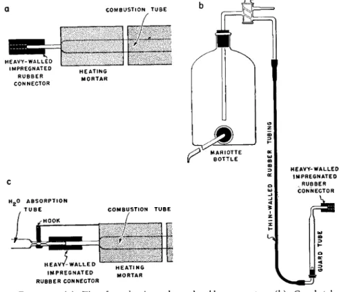
A rubber connector (using a trace of glycerin) is attached to the tip of the combustion tube leaving one-half of the rubber tubing extending beyond the tip so that the water absorption tube may be inserted later (Fig. 1 3 1 a ) . The rubber connector should not make contact with the side of the heating mortar and it should be left permanently attached to the tip. The extending portion of the rubber connector should be only long enough so that it will eventually cover the capillary of the absorption tube almost up to the small bulb portion (about 18 mm. from the end).
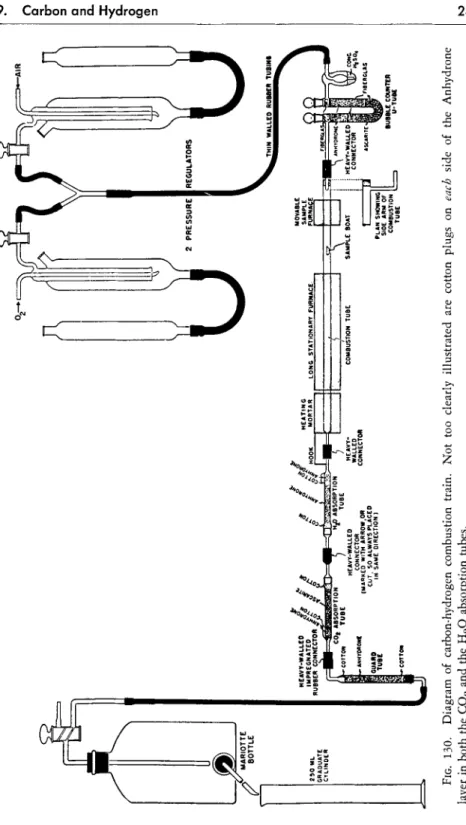
FIG. 130. Diagram of carbon-hydrogen combustion train. Not too clearly illustrated are cotton plugs on each side of the Anhydrone layer in both the C02 and the H20 absorption tubes.
247 Assembling the Combustion Train
The screw clamp holding the combustion tube is loosened so that the tube may freely expand on heating. Oxygen, under a pressure head of several centimeters, is passed through the tube and the heating mortar and both long and short furnaces are switched on. When operating temperatures have been reached ( 1 7 5 ° - 1 9 0 ° C .2 4'2 5-5 4'1 1 2'1 1 3'2 8^ ^ for the heating mortar and 680° C .1 0 4'3 4 9'3 5 0 for the two furnaces) the tube is pushed up against the heating mortar so that there is no more play, and securely clamped in place.
HEAVY-WALLED IMPREGNATED
, R U B B E R CONNECTOR
H E A V Y - W A L L E D I M P R E G N A T E D RUBBER CONNECTOR
FIG. 131. ( a ) Tip of combustion tube and rubber connector, ( b ) Guard tube, Mariotte bottle, ( c ) Hook on heating mortar making contact with absorption tube capillary.
The hot short furnace is moved the length of the tube between the clamp and the long furnace to remove any combustible material. The short furnace is switched off and oxygen is passed through the hot tube overnight. Once the long furnace and heating mortar are brought up to working temperatures, they are never switched off for the entire life of the combustion tube.
After* the tube has been heated overnight with oxygen passing through,
* This test cannot be made until the tube has been heating overnight and all com
bustible material and moisture have been driven out.
it must be tested for a possible leak by stoppering the rubber connector attached to the tip. Under these conditions, no gas should pass through the bubble counter. I f the tube is gas-tight, proceed as below.
A rubber connector is attached, with the aid of a trace of glycerin to the horizontal piece at the top of the filled guard tube leaving one-half of the rubber tubing extending beyond the end of the glass so that the Ascarite absorption tube may be connected here (Fig. 1 3 1 b ) . The other end of the guard tube is connected to the vertical tube of the three-way stopcock at the top of the Mariotte bottle, by means of rubber tubing, forming a permanent connection. The Mariotte bottle is filled with water and the graduate cylinder placed in position to collect the water which will come from the former.
PRESSURE R E G L / L A T / O N1 1 2'1 1 3'2 8 4'2 8 5'3 0 8'3 1 7 - 3 2 0'3 5 0
After the new tube has been burned out overnight, a pressure regulation must be performed to determine the pressure head needed to pass oxygen or air through it at the rate of 1 0 * ml. per minute. Since the bubble counter-U-tube is connected between the pressure regulator and the combustion tube, a new pressure regulation must be done again whenever a new bubble counter-U-tube is attached to an old combustion tube.
The air pressure regulator is adjusted to a height of 5 - 1 0 cm. and the stopcocks turned so that only this one is connected to the bubble counter- U-tube and air flows through the system.
A trace of glycerin is added to the tips of the two absorption tubes and they are joined by means of a rubber connector so that the two ground joints are together and the capillary tips of the plugs form a glass-to-glass contact.
The rubber connector is marked with an arrow, or the end trimmed, so that each end is always attached to the same absorption tube. By so doing, the gas will always flow through any exposed portion in the same direction.
The free end of the Anhydrone tube is inserted into the rubber connector on the tip of the combustion tube, effecting a glass-to-glass contact between the two capillary ends (Figs. 130 and 1 3 1 c ) .
The free end of the Ascarite tube is connected to the guard tube by means of the rubber connector, effecting a glass-to-glass contact. The drainage tube of the Mariotte bottle is lowered so that it makes an angle of 2 0° - 3 0 ° below the horizontal.
With the entire combustion train connected—pressure regulator, bubble counter-U-tube, combustion tube, two absorption tubes, guard tube and Mariotte bottle—the three stopcocks are set as follows: (a) on the oxygen pressure regulator, closed ( b ) on the air pressure regulator, open ( c ) on the Mariotte
* Twelve milliliters per minute for the more experienced analyst.
249 Assembling the Combustion Train
bottle, open so that air can enter from the combustion train and water flow out through the drainage tube. The amount of water dropping into the gradu
ate cylinder is equal to the volume of air passing through the system. The quantity per minute should be noted. The drainage tip should be raised or lowered, as indicated to regulate the flow to a speed of 1 0 * ml. per minute.
When this has been attained, the rate at which the air bubbles pass through the water in the Mariotte bottle, via the vertical glass tube is recorded. For example, let us assume that during a 10-second interval, 15 bubbles rise in the Mariotte bottle for a speed of 1 0 * ml. per minute. Therefore, at any later date, we will know that if 15 bubbles rise in the Mariotte bottle in 10 seconds, gas is passing through at the rate of 1 0 * ml. per minute. This is used as the measure rather than observing the rate of flow of the water.
After the flow has been adjusted to a speed of 1 0 * ml. per minute, the rate at which bubbles pass through the sulfuric acid in the bubble counter is recorded. For example, let us assume that 22 bubbles pass through during a 10-second interval, corresponding to 1 0 * ml. per minute.
The two absorption tubes, the guard tube, and Mariotte bottle are then disconnected from the combustion tube. The height of the sodium hydroxide in the air pressure regulator is then adjusted, by means of the leveling tube, to that necessary to cause the gas to pass through the combustion tube at the rate of 1 0 * ml. per minute or, in our example, above, at the rate of 22 bubbles in 10 seconds through the bubble counter. This height of the sodium hydroxide is always maintained throughout the life of the bubble counter-U- tube combination as explained above.
The oxygen pressure regulator is adjusted to the same liquid level as the air regulator. Because one of the regulators might have been incorrectly graduated, it is advisable to make a rapid check on the oxygen one the first time a pair is used.
The data obtained during the pressure regulation should be permanently recorded. For example, if the conditions above were accompanied by a regula
tion of 9.7 cm. of sodium hydroxide, the record kept for 1 0 * ml. per minute would be:
Pressure regulator 9-7 cm.
Bubble counter 22 bubbles/10 seconds Mariotte bottle 15 bubbles/10 seconds
The bubble counter is necessary for obtaining the pressure regulation, but the author prefers to use thereafter only the height of the pressure regulator and the rate through the Mariotte bottle for the daily adjustment of the train as explained in the following pages.
* Twelve milliliters per minute for the more experienced analyst.