Microdetermination of Some Physical Constants
I. MICRODETERMINATION OF MELTING POINT II. MICRODETERMINATION OF BOILING POINT III. MICRODETERMINATION OF SPECIFIC GRAVITY
IV. MICRODETERMINATION OF OTHER PHYSICAL CONSTANTS
Although this book deals with quantitative organic microanalysis, it is felt that brief descriptions of the methods of obtaining some of the more common physical constants are in order. Melting point, boiling point, and specific gravity are the constants most commonly determined4 6 and consequently methods for these will be described while mere mention of some of the rest will be made.
/. MICRODETERMINATION OF MELTING POINT
The melting point determination performed in the usual manner is in reality a micromethod. It is assumed that the reader has had considerable experience with the above procedure. The author wishes to point out that the above is the most reliable one when the proper corrections are made (calibration of the thermometer and correction for exposed s t e m4 6-7 2) and should always be used when possible. A new commercially available apparatus8 9 for determining melt
ing points was described in connection with the Rast method for the deter
mination of molecular weight (Fig. 203, Chapter 2 1 ) . On occasions when material is scarce it is desirable to use another method for which microscopic quantities of substance are required. Even when adequate quantities of material are available, the microscopic method may be used to advantage. For example, with it the presence of more than one compound in a sample is demonstrated easily, since each individual crystal can be observed during the melting process.
In such cases, under the microscope each substance is seen to melt sharply at its own melting point, unaffected by the other. Also the method can be used successfully to identify various substances2-4 9»5 1 and the author has used it to advantage on numerous occasions.* The Arthur H. Thomas Company,8 9 the
548
* During the period of operation of the author's laboratory, manufacturing problems
549 Melting Point
manufacturer of the apparatus used, has prepared a pamphlet giving a rather complete bibliography on this subject.
Apparatus89
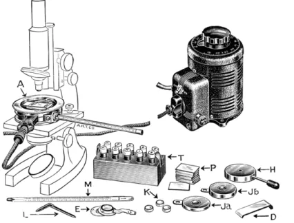
The apparatus assembly required is shown in Fig. 2 1 0 . It consists of an elec
trically heated hot stage into which is inserted a thermometer. The sample is placed on a microscopic slide which rests directly upon the heated metal sur-
FIG. 2 1 0 . Kofler micro melting point apparatus and accessory parts. ( A ) Micro hot stage. ( D ) Baffle. ( L ) Tool. ( M ) Thermometer. ( T ) Test reagents. ( P ) Microslides.
( E ) Vacuum sublimation chamber. ( H ) Cooling block. ( J a , J b ) Sublimation blocks.
( K ) Sublimation dishes.
have arisen, particularly in regard to the aging of pharmaceuticals in ampul form used for parenteral injection. Since the amount of active ingredient in each ampul is usually a matter of a few milligrams, products of deterioration usually amount to a matter of micrograms (compare the section on ampul testing by the manometric apparatus, Chapter
1 8 ) . If precipitates result from the deterioration they are heated routinely with the apparatus described below before proceeding with an analysis. In this way, the author has been able to detect the presence of several substances in a precipitate, weighing a small fraction of a milligram, as well as to identify at least one or two components of it within a matter of minutes. For example, elementary sulfur acts very characteristically—
it melts and then sublimes in the form of tiny yellow droplets on the upper microscopic slide (see below). Sometimes the elementary sulfur is present as a contaminant and the melting stage cannot be noticed because of the relatively small quantity but the char
acteristic sublimate can be seen always.
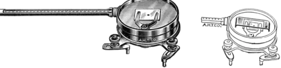
face. Over the sample is placed a coverglass and the combination covered by a raised baffle (Fig. 2 1 1 ) . A glass plate, ground around the outer rim to insure close contact with the metal parts to prevent circulation of air currents, is used as a cover. The assembly is placed on the stage of a microscope so that the
FIG. 2 1 1 . (Left) Kofler micro melting point apparatus, coverglass and baffle removed.
(Right) Baffle in position on apparatus.
sample can be viewed through the objective lens and eye piece. The hot plate is connected to the electric service through a suitable variable transformer for controlling the temperature. The thermometer is calibrated by determining the melting points of a number of standards whose corrected melting points are known. In this manner, the melting points obtained with unknown samples
FIG. 2 1 2 . Cold stage for microdetermination of freezing points for use on stage of microscope similar to Kofler micro melting point apparatus (see Fig. 2 1 0 ) .
are the corrected ones. (Note: The hot stage is equipped also with sublima
tion units—Fig. 2 1 0 . )
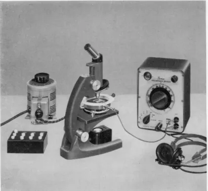
A cold stage for determining freezing points of liquids is also commercially available8 9 (Fig. 2 1 2 ) , as well as an audiohm thermistor attachment which permits the determinations without removing the eye from the microscope
(Fig. 2 1 3 ) . Other advantages of the thermistor method are faster response, obtained by locating a smaller sensor closer to the field of observation than
551 Melting Point
is possible with a thermometer, and the elimination of stage-calibrated ther
mometers. Uninterrupted observation of the fusion through all its phases is made possible by measuring the temperature as a function of the thermistor resistance, determined at any instant by nulling the audible bridge signal.
FIG. 213. Audiohm thermistor attachment for Kofler micro melting point apparatus.
Procedure
In the p r o c e d u r e1 4'1 6'3 7'3 8'4 8-5 2'6 0-7 9'8 0-8 2-8 7'8 9'9 2'9 6 the micro hot plate with in
serted thermometer is set on the stage of a microscope. A small amount of sam
ple is placed on a microscopic slide ( 2 5 X 37 mm.) and covered with a micro coverglass. The combination then is placed directly on the metal micro hot stage, and over the glasses is placed a glass baffle (Fig. 2 1 1 ) . Finally, the large circular glass plate with the ground rim is set on top of the metal rim of the hot plate. The source of electricity is attached and the temperature slowly raised. As the melting point is approached, the rate of temperature rise should be reduced to that of 0.5° C. per minute. The micro melting point is that temperature at which the smaller crystals have changed into droplets and the outlines of the larger crystals start to round off. In this manner the micro
melting point obtained is that at which the solid and liquid phases are in equilibrium. I f the substance is stable at its melting point, cooling about 0.5°
C. causes the crystals to start growing.
//. MICRODETERMINATION OF BOILING POINT
When enough material is available, miniature distillation flasks and columns of the same designs as ordinarily employed in the organic laboratory, may be used to obtain the boiling range of the liquid in question. However, when only fractions of a milliliter are available the boiling point is obtained readily by use of the following procedure. The method is of limited value since it is adaptable only to pure compounds.4 6
Apparatus46,87
MELTING POINT BATH
An ordinary melting point bath, mechanically stirred, of the type recommended for the Rast molecular weight determination is required.
THERMOMETERS
Calibrated Anschutz thermometers of the desired ranges are required. An auxiliary thermometer, 0 - 2 5 0 ° C. range, is used when corrections for the ex
posed stem are made.
BOILING POINT CAPILLARIES
Glass tubing is drawn out so as to obtain a section of about 2- 3 mm. I.D. and about 150 mm. in length. A needle-point flame from a blast lamp is used to seal off a small length about 4 0 - 5 0 mm. from the one end. The smaller end is then cut off with a file so that the sealed off portion is about 6 - 8 mm. in length from the open end up to the seal (see Fig. 2 1 4 ) . (It is preferable to make the capillary boiling tube in this manner rather than to attempt to seal off the small section at a distance of about 6 - 8 mm. from the open end.) This small tube acts as a condenser.
SMALL TEST TUBE
A small Pyrex2 1 test tube (approximately 7 mm. χ 50 mm.) is used as the distilling vessel. I f this size is too large for the amount of sample, a smaller tube may be made by sealing off the proper size of glass tubing.
553 Boiling Point
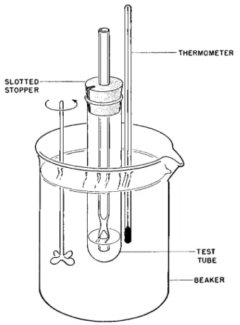
THERMOMETER
B E A K E R
FIG. 214. Apparatus for microdetermination of boiling points.
Procedure4
The sample is placed in the small test tube and the capillary or condenser tube is put into place with the aid of a slotted stopper. ( T h e test tube must not be stoppered shut on inserting the condenser. It must be open to the atmosphere.) The condenser tube should be immersed to a depth of about 2-3 mm. in the liquid as shown in the Fig. 214. The test tube and condenser capillary are mounted in the heating bath as shown. The depth of the liquid (Crisco* or silicone fluid) in the bath should be great enough (about 7 cm.) so that it extends about 3 cm. below the bottom of the test tube and the same distance above the glass seal in the condenser. The Anschutz thermometer is attached to the test tube with the center of the mercury-filled bulb at the same level as that of the liquid under test. The bath is vigorously stirred
* Hydrogenated vegetable o i l .7 4
(mechanically) and heated. As the temperature rises, the air trapped in the condenser tube expands and escapes from the lower open end. The temperature is raised until it is above the boiling point of the liquid under test as shown by the cessation of escaping air. The temperature of the bath is lowered slowly (0.5° C. per minute), during which vapor bubbles cease to emerge from the lower end, and then the liquid begins to suck back into the condenser tube. The boiling point is that temperature at which the level of the liquid in the con
denser capillary is the same as that outside of it. At this temperature the liquid is in equilibrium with the vapor. The apparatus should be calibrated using several pure substances of known boiling points covering the desired range, after which the necessary corrections should be made when working with unknowns. It is also advisable to use corrections for the exposed stem accom
plished in the usual manner. For this the bulb of an auxiliary thermometer is placed against the Anschiitz, midway between the surface of the liquid bath and the mark representing the boiling point. The average stem temperature is obtained thusly and used in the following formula4 6-7 2:
Correction for exposed stem = + N ( / — / ' ) 0.000154 where
Ν = the number of degrees on the stem of the thermometer between the surface of the bath liquid and the temperature read
/ = the temperature read on the Anschiitz thermometer
/' = the average temperature of the exposed mercury column (as read on the auxiliary thermometer)
0.000154 = apparent coefficient of expansion of mercury in glass
The correction obtained by calculation is added to the recorded temperature in addition to whatever corrections ( - | - or — ) are necessary from the calibration of the thermometer.
///. MICRODETERMINATION OF SPECIFIC GRAVITY USING THE GRAVITOMETER
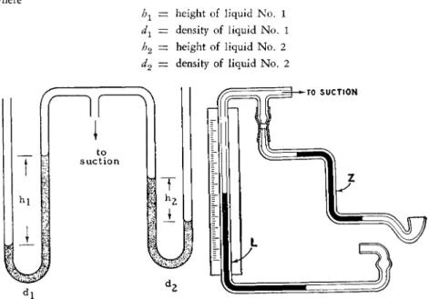
The specific gravity of liquids may be determined quickly, making use of the principle of hydrostatic b a l a n c e .2 3 , 3 2 When two U-tube manometers containing liquids of different densities are connected to a common source of reduced pressure, the heights of the liquids in the connecting manometers are inversely proportional to their densities (see Fig. 215, left) as expressed by the follow
ing equation:
b1d1 = h2d2
or h1 d2
h2 ~ d1
555 Specific Gravity
where
h1 — height of liquid No. 1 dx — density of liquid No. 1 h2 — height of liquid No. 2 d2 — density of liquid No. 2
FIG. 215. Diagrams showing details of Fisher-Davidson gravitometer. (Left) Prin
ciple. (Right) Diagram of apparatus.
The apparatus shown in the Figs. 2 1 5 , right, and 2 1 6 has been designed so that a direct reading of spécifie gravity is obtained when a reference liquid is used along with the unknown. The height of the liquid No. 2, the un-
FIG. 216. Fisher-Davidson gravitometer, commercial model.
known, is held constant at a height equal to S in the Ζ tube. When the refer
ence liquid No. 1 is ethylbenzene (d20 = 0 . 8 6 7 ) , the above equation becomes b1 X 0.867 = Sd2
Sd2
or h, — ——
1 0.867
Now if S is equal to 0.867 unit of the scale attached to the vertical portion of the tube, L, the equation becomes
0.867^2 h, = 0.867 or h± — d2
The tube, Z, containing the unknown is a simple manostat which, within limits, insures a fixed pressure difference between the atmosphere and the tube connecting the two tubes, L and Z. The value of this fixed pressure varies directly with the density of the liquid contained in the tube, Z, and is measured by means of the L-tube manometer, which is fitted with a scale graduated in terms of d20. Consequently, reading the scale attached to the tube, L, gives a direct reading of the specific gravity of the liquid at 2 0 ° C. compared with water at 4 ° C. (d2£) over the range 0 . 6 0 0 - 2 . 0 0 0 , when ethylbenzene is the ref
erence liquid. I f some other reference is placed in the tube, L, a factor must be applied. For example, for specific gravities above 2.000, carbon tetrachloride is used, and then the scale readings must be multiplied by the ratio
sp. gr. of CC14 1.595
sp. gr. of C6H5C2H5 "~ 0.867
= 1.84
For most organic liquids the readings obtained correspond closely for d20
even if made at temperatures several degrees above or below 2 0 ° C. This is true since the measurement of one organic liquid (the unknown) is made relative to another one (the reference), and most organic liquids have tempera
ture coefficients of density which lie within a narrow range.9-3 2 On the average, the values of specific gravity observed at 20 zb 5° C. will not differ by more than 0 . 1 % from those observed at 2 0 ° C *
* Where the coefficient of expansion of the liquid under test is known, the correction, calculated from the following formula, is added to the observed value:
( / — 2 0 ° ) ( Cx — 0.101) (dQhJ
Correction ~ · 100
where / = temperature at which the observation is made Cx = coefficient of expansion of the liquid
0.101 = percentage change in the density of ethylbenzene in the vicinity of 20° C.
^( ) b s = observed density reading.
557 Specific Gravity
Reagents
ETHYLBENZENE*2
Pure ethylbenzene (d20 = 0 . 8 6 7 ) is required as the reference liquid for meas
urements on unknowns whose specific gravities are in the range of 0 . 6 0 0 - 2.000.
CARBON TETRACHLORIDE32
Pure carbon tetrachloride (d20 = 1.595) is required as the reference liquid, in place of ethylbenzene, for measurements on unknowns whose specific gravities are above 2.000. When carbon tetrachloride is used, the scale readings must be multiplied by
1.595
Apparatus
The a p p a r a t u s2 2 , 3 2 , 8 7 used is the Fisher-Davidson gravitometer and is shown in Figs. 215, right, and 216. It consists of the tube, L, which contains the refer
ence liquid, No. 1, and a tube, Z, for the unknown. The tubes are connected to a common source of reduced pressure produced by the movement of a milled knob counterclockwise along a section of rubber tubing.
For most organic liquids the standard tube, Z, which is approximately 1.9 mm. I.D., requiring about 0.3 ml. of sample, is used. For samples of low viscosity, the bore of the tube may be even less. For liquids of high viscosity, tubes of approximately 2.6-3.0 mm. I.D. or even 4 mm. may be used. The former requires about 1.0 ml. and the latter about 2.0 ml. of sample, re
spectively. The larger bores are necessary because equilibrium is obtained more slowly with this type of material.
Procedure23 32 87
The reference liquid (ethylbenzene for the range 0.600-2.000, or carbon tetrachloride for the range above 2.000) is added to the tube, L, through the lower end until the liquid level stands between the two marks of the receptacle on the right arm. ( I f air pockets are present, the milled knob on the suction device is turned counterclockwise as far as possible. The rubber connector between the two tubes, L and Z, is pinched and the milled knob turned slowly in a clockwise direction, forcing the liquid back into the receptacle where the air will be expelled. Then the milled knob is slowly turned counterclockwise to return the liquid free from air pockets.)
The milled knob of the suction device is turned clockwise as far as pos
sible. The tube, Z, is connected to the tube, L, by means of the rubber con
nector and then clamped into place on the support. The instrument is made level by means of the leveling screws provided for this purpose. Sufficient unknown sample is added to fill completely the cup of the tube, Z. Then the milled knob is turned slowly counterclockwise drawing the liquid up into the tube, Z, so that the menisci stand approximately in the middle of the horizontal arms of the tube, Z. ( I f the menisci do not reach the above points, the liquid is returned to the cup by reversing the knob and making the neces
sary adjustment. I f air pockets are present in the capillary of the tube, Z, the receptacle of the tube, L, is stoppered and the milled knob turned so as to return the liquid in the tube, Z, to the cup momentarily.) The slide on the scale is moved until the index coincides with the meniscus of the reference liquid in the tube, L, and the position of the index on the scale is read, estimating the third decimal place. The result is the specific gravity of the liquid at 2 0 ° C. compared with water at 4 ° C. (d20). It is good practice to move the liquid in the tube, Z, forward and backward, slightly, by means of the milled knob, and then check the reading. This insures that equilibrium has been reached.
A summary of the operations is given by the following:
1. The level of the standard in the right arm of the tube, L, should be between the two etched lines
2. Turn the milled knob to the extreme right (clockwise) 3. Connect the tube, Z, to tube, L
4. Level instrument
5. Add sufficient liquid of unknown specific gravity to fill completely the cup of the tube, Ζ
6. Turn the milled knob to the left (counterclockwise) until the liquid is drawn up into the tube, Z, so that the menisci stand approximately in the middle of the horizontal arms of the tube, Ζ
7. Read the level of the standard in the tube, L, to the third decimal.
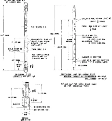
USING MICRO WEIGHING PIPETTES, DENSITY-TYPE (PYCNOMETERS)
The specific gravity may be determined with the aid of weighing pipettes or pycnometers1'6 9'8 8 of the types shown in Fig. 217. These are used in the same manner as are regular pycnometers with which the reader should be familiar, being weighed empty and then full. Knowing the weight, temperature, and volume, the specific gravity is obtained.
559 Specific Gravity
Three sizes are specified, designed for the determination of density on small amounts of volatile, viscous, or hygroscopic liquids. Most of the sub
stance can easily be recovered after the determination. The decigram size has a capacity of 100 microliters and is especially suitable for highly viscous liquids.
The centigram size has a capacity of 4 0 - 8 0 microliters, and the milligram size a capacity of 1 0 - 3 0 microliters. The centigram and milligram sizes are graduated in one mm. divisions and can be used even when the total amount
13-20
5.0-5.5 MM 0 0 .
GRADUATION RING AT / LEAST 5MM FROM
EITHER END OF CAPILLARY 7 MM MAX. 0 0 ALL CAPILLARIES 5.0 - 5.5 MM 0 0.
0 5-0.75 MM ID.
, EACH 5 AND 10 MM L I N E Al LEAST · | RINGS EACH I MM LINE AT LEAST
χ RING
\- 5 0 - 5 5 MM 0 0 CENTIGRAM TYPE
10 0 7 5 - I 00 MM MILLIGRAM TYPE ·
ID 0 4 0 - 0 6 0 MM
NUMBER 2 OMITTED LINE AT 2 MAY BE OMITTED j WHEN TIP IS 20MM. LONG 13-20 MM
I PEÇIGRAM TYPE
CAPACITY 100 μΙ t I μΙ CENTIGRAM AND MILLIGRAM TYPE APPROX. CAPACITIES' CENTIGRAM : 4 0 - 8 0 u l
MILLIGRAM 10-30 μΙ
FIG. 2 1 7 . Micro weighing pipettes, density-type (pycnometers)—details of construction.
of sample available is less than the maximum capacity of the micropipette.
The sample may occupy any portion of the graduated stem, thereby eliminating the necessity of making a precise adjustment to a fixed calibration mark.
The pipettes are calibrated according to the directions given in Chapter 5 or by the methods proposed by Alber.1 Water, bromoform, or mercury are used for the decigram size (with mercury, the operation is more difficult).
With the centigram and milligram sizes, measurement of the bore by means of a microscope followed by the use of distilled water is sufficient. T h e reader is referred to the original literature.1'8 8
IV. MICRODETERMINA Τ ION OF OTHER PHYSICAL
The determination of other constants such as the refractive index, optical rotation, etc., can be determined also on a microscale and will be briefly dis
cussed. For details of the methods the reader is referred to the literature cited.
REFRACTIVE INDEX
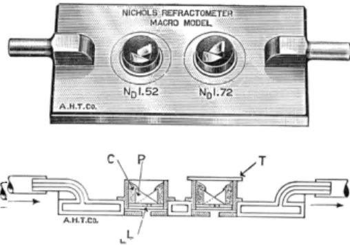
The refractive index as determined by the ordinary refractometers found in the laboratory may be considered to be a microdetermination because one drop of liquid is required. However, a truly m i c r o r e f r a c t o m e t e r2'3'3 6'6 8'8 4'8 7-9 1 is com
mercially available8 9 which requires 6 - 8 cu. mm. of sample, 5 - 6 of which can
FIG. 218. (Top) Nichols refractometer. (Bottom) Cross-section of Nichols refrac- tometer, indicating water circulation within jacket. ( C ) Cement. ( P ) Prism. ( L ) Engraved line. ( T ) Coverglass.
be recovered, depending upon the physical properties. The instrument is shown in Fig. 218. Jelley4 4 also designed an instrument which is rapid and simple and uses 0.1 cu. mm. of liquid.
The refractive index of a solid may be determined by a comparison under the microscope with standard samples prepared from a variety of powdered g l a s s3 0-7 6
OPTICAL ROTATION
The optical rotation of an optically active compound may be done on a micro- scale by using a micropolarimeter tube and an ordinary p o l a r i m e t e r .2 4'2 7'2 8-3 8'7 9-8 1
CONSTANTS
561 Table of References
T A B L E 38
ADDITIONAL INFORMATION ON R E F E R E N C E S * R E L A T E D TO C H A P T E R 22
In addition to the procedures presented in the preceding pages of this chapter, the author wishes to call to the attention of the reader the references listed in Table 38.
(See statement at top of Table 4 of Chapter 1, regarding completeness of this material.) Books
Belcher and Godbert, 4, 5 Chamot and Mason, 14 Cheronis, 15
Cheronis and Entrikin, 16, 17 Clark, Ε. P , 18
Clark, S. J . , 19
Emich and Schneider, 25 Gibb, 36
Grant, 37, 38 Kamm, 46
Kofler and Kofler, 49, 50
Kofler and Kofler with Brandstâtter, 51 Kofler, Kofler, and Mayrhofer, 52 Pharmacopeia, 72
Roth, 7 8 - 8 1 Schneider, 82 Shriner and Fuson, 84 Shriner, Fuson, and Curtin, 85 Steyermark, 87
Weissberger, 9 1 , 92
Melting point (freezing point) Brandenburg and Frobose, 10 Brandstâtter and Thaler, 12 Chakravarti and Chaudhuri, 13 Fischer, R., 29
Fischer and Reichel, 31 Hewitt, 39
Hilbck, 40
Hippenmeyer, 4 1 , 42 Hozumi and Morita, 43 Kofler and Kofler, 53 Kofler and Sitte, 54 Kofler, 55
Maffei and Wasicki, 57 Mastrangelo and Aston, 58 Matthews, 59
Melting point (freezing point) (Conf.) Morton and Mahoney, 64
Miiller and Zenchelsky, 65 Opfer-Schaum, 70 Owen and Reid, 71 Pinkus and Waldrep, 73 Sekera and Pokorny, 83 Somereyns, 86 Tschamler, 90 Wiegand, 94 Yanagimoto, 95 Boiling point
Bôhmc and Bôhm, 7 Emich and Schneider, 25 Garcia, 35
Morton and Mahoney, 64 Owen and Reid, 71
Wiberley, Siegfriedt, and Benedetti-Pich
ler, 93 Wiegand, 94
Specific gravity (density) Alber, 1
Belcher and Godbert, 4, 5 Blank and Willard, 6 Clemo and McQuillen, 20
Fenger-Eriksen, Krogh, and Ussing, 26 Furter, 34
Nettesheim, 67
Rosebury and Van Heyningen, 77 Optical rotation
Donau, 24 Fischer, E., 27, 28 Kacser and Ubbelohde, 45
McCrone, 60, 61
McCrone and Massenberg, 62 McCullough and Waddington, 63
Vapor pressure
Bonhorst, Althouse, and Triebold, 8 Nash, 66
* The numbers which appear after citations in the reference list at the end of
ι entry in this table refer to the literature chapter.
T A B L E 38 (Continued)
Refraction, molecular refraction, re- Refraction, molecular refraction, re fractive index
Alber and Bryant, 3
Brandstâtter-Kuhnert and Martinek, 11 Frediani, 33
Kirk and Gibson, 47 Reihlen, 75
Viscosity
Labout and van Oort, 56 fractive index (Conf.) Reimers, 76
Roth, 7 8 - 8 1
REFERENCES
1. Alber, H. K., Ind. Eng. Chem., Anal. Ed., 12, 764 ( 1 9 4 0 ) . 2. Alber, H. K., Mikrochemie ver. Mikrochim. Acta, 29, 294 ( 1 9 4 1 ) .
3. Alber, H. K., and Bryant, J . T., Ind. Eng. Chem., Anal. Ed., 12, 305 ( 1 9 4 0 ) . 4. Belcher, R., and Godbert, A. L., "Semi-Micro Quantitative Organic Analysis," Long
mans, Green, London, New York, and Toronto, 1945.
5. Belcher, R., and Godbert, A. L., "Semi-Micro Quantitative Organic Analysis," 2nd ed., Longmans, Green, London, 1954.
6. Blank, E. W., and Willard, M. L., / . Chem. Educ, 10, 109 ( 1 9 3 3 ) . 7. Bôhme, H., and Bôhm, R. H., Mikrochim Acta, p. 270 ( 1 9 5 9 ) .
8. Bonhorst, C. W., Althouse, P. M., and Triebold, H. O., / . Am. Oil Chemists' Soc, 26, 375 ( 1 9 4 9 ) .
9. Bosart, L. W., Perfumery Essent. Oil Record, 30, 145 ( 1 9 3 9 ) . 10. Brandenburg, V . W., and Frobose, H., Pharmazie, 9, 1009 ( 1 9 5 4 ) .
11. Brandstâtter-Kuhnert, M., and Martinek, Α., Mikrochim. Acta, p. 803 ( 1 9 5 8 ) . 12. Brandstàtter, M., and Thaler, H., Mikrochemie ver. Mikrochim. Acta, 38, 358
( 1 9 5 1 ) .
13. Chakravarti, R. N., and Chaudhuri, Κ. N., Bull. Calcutta School Trop. Med., 4, 16 ( 1 9 5 6 ) .
14. Chamot, Ε. M., and Mason, C. W., "Handbook of Chemical Microscopy," 2nd ed., Vol. I, p. 207, Wiley, New York, and Chapman & Hall, London, 1938.
15. Cheronis, N. D., "Semimicro and Macro Organic Chemistry," Crowell, New York, 1942.
16. Cheronis, N. D., and Entrikin, J . B . , "Semimicro Qualitative Organic Analysis," p.
36, Crowell, New York, 1947.
17. Cheronis, N . D., and Entrikin, J . B . , "Semimicro Qualitative Organic Analysis,"
2nd éd., Interscience, New York, 1957.
18. Clark, E. P., "Semimicro Quantitative Organic Analysis," Academic Press, New York, 1943.
19. Clark, S. J . , "Quantitative Methods of Organic Microanalysis," Butterworths, Lon
don, 1956.
20. Clemo, G. R., and McQuillen, Α., / . Chem. Soc, p. 1220 ( 1 9 3 5 ) . 21. Corning Glass Works, Corning, New York.
22. Davidson, D., Popowsky, M., and Rosenblatt, P., U. S. Patent 2,328,787 ( 1 9 4 3 ) . 23. Davidson, D., and Popowsky, M., 102nd Meeting of the American Chemical Society,
Division of Analytical and Micro Chemistry, p. L l 7 , Atlantic City, New Jersey, September 1941.
24. Donau, J . , Monatsh. Chem., 29, 333 ( 1 9 0 8 ) .
25. Emich, F., and Schneider, F., "Microchemical Manual," Wiley, New York, 1934.
563 References
26. Fenger-Eriksen, Κ., Krogh, Α., and Ussing, H., Biochem. J., 30, 1264 ( 1 9 3 6 ) . 27. Fischer, E., Ber., 44, 129 ( 1 9 1 1 ) .
28. Fischer, E., Ber., 54, 1979 ( 1 9 2 1 ) .
29. Fischer, R., Mikrochemie ver. Mikrochim. Acta, 36/37, 296 ( 1 9 5 1 ) .
30. Fischer, R., and Kocher, C , Mikrochemie ver. Mikrochim. Acta, 32, 173 ( 1 9 4 4 ) . 31. Fischer, R., and Reichel, Z., Mikrochemie ver. Mikrochim. Acta, 31, 102 ( 1 9 4 4 ) . 32. Fisher Scientific Company, Tech. Serv. Dept. Pamphlet on the Fisher-Davidson
Gravitometer No. 11-509, New York, and Pittsburgh, Pennsylvania.
33. Frediani, Η. Α., Ind. Eng. Chem., Anal. Ed., 14, 439 ( 1 9 4 2 ) . 34. Furter, M. F., Helv. Chim. Acta, 21, 1674 ( 1 9 3 8 ) .
35. Garcia, C. R., Ind. Eng. Chem., Anal. Ed., 15, 648 ( 1 9 4 3 ) .
36. Gibb, T. R. P., Jr., "Optical Methods of Chemical Analysis," pp. 208, 209, 336, McGraw-Hill, New York, 1942.
37. Grant, J . , "Quantitative Organic Microanalysis," Based on the Methods of Fritz Pregl," 4th ed., Blakiston, Philadelphia, Pennsylvania, 1946.
38. Grant, J . , "Quantitative Organic Microanalysis," 5th ed., Blakiston, Philadelphia, Pennsylvania, 1951.
39. Hewitt, E. J . , Chem. & Ind. (London), p. 42 ( 1 9 4 7 ) .
40. Hilbck, H., Mikrochemie ver. Mikrochim. Acta, 36/37, 307 ( 1 9 5 1 ) . 41. Hippenmeyer, F., Mikrochemie ver. Mikrochim. Acta, 39, 409 ( 1 9 5 2 ) . 42. Hippenmeyer, F., Pharm. Acta Helv., 25, 161 ( 1 9 5 0 ) .
43. Hozumi, K., and Morita, N., Yakugaku Zasshi, 79, 1028 ( 1 9 5 9 ) . 44. Jelley, Ε. E., / . Roy. Microscop. Soc, 54, 234 ( 1 9 3 4 ) .
45. Kacser, H., and Ubbelohde, A. R., / . Soc. Chem. Ind. (London), 68, 135 ( 1 9 4 9 ) . 46. Kamm, O., "Qualitative Organic Analysis," pp. 116, 119, Wiley, New York, 1923.
47. Kirk, P. L., and Gibson, C. S , Ind. Eng. Chem., Anal. Ed., 11, 403 ( 1 9 3 9 ) . 48. Kofler, L., Mikrochemie, 15, 242 ( 1 9 3 4 ) .
49. Kofler, L., and Kofler, Α., "Mikro-Methoden zur Kennzeichnung organischer Stofïe und Stoffgemische," Wagner, Innsbruck, 1948.
50. Kofler, L., and Kofler, Α., "Mikroskopische Methoden," in "Handbuch der mikro- chemischen Methoden" ( F . Hecht, and M. K. Zacherl, eds.), Band I, T l . 1, Springer, Wien, 1954.
51. Kofler, L., and Kofler, Α., in cooperation with Brandstâtter, M., "Thermo-Mikro- Methoden zur Kennzeichnung organischer Stofïe und Stoffgemische," 3rd ed., Verlag Chemie, Weinheim/Bergstrasse, 1954
52. Kofler, L., Kofler, Α., and Mayrhofer, Α., "Mikroskopische Methoden in der Mikrochemie," Haim, Vienna, 1936.
53. Kofler, L., and Kofler, W., Mikrochemie ver. Mikrochim. Acta, 34, 374 ( 1 9 4 9 ) . 54. Kofler, L , and Sitte, H., Monatsh. Chem., 81, 619 ( 1 9 5 0 ) .
55. Kofler, W., Mikrochemie ver. Mikrochim. Acta, 39, 84 ( 1 9 5 2 ) . 56. Labout, J . W . Α., and Oort, W . P. van, Anal. Chem., 28, 1147 ( 1 9 5 6 ) . 57. Maffei, F. J . , and Wasicki, R., Anais assoc. quim. Brasil, 7, 111 ( 1 9 4 8 ) . 58. Mastrangelo, S. V . R., and Aston, J . G., Anal. Chem., 26, 764 ( 1 9 5 4 ) . 59. Matthews, F. W., Anal. Chem., 20, 1112 ( 1 9 4 8 ) .
60. McCrone, W . C , Anal. Chem., 21, 436 ( 1 9 4 9 ) .
6 1 . McCrone, W . C , Mikrochemie ver. Mikrochim. Acta, 38, 476 ( 1 9 5 1 ) . 62. McCrone, W . C , and Massenberg, S., Anal. Chem., 28, 1038 ( 1 9 5 6 ) . 63. McCullough, J . P., and Waddington, G., Anal. Chim. Acta, 17, 80 ( 1 9 5 7 ) . 64. Morton, Α. Α., and Mahoney, J . F., Ind. Eng. Chem., Anal. Ed., 13, 498 ( 1 9 4 1 ) . 65. Millier, R. H., and Zenchelsky, S. T., Anal. Chem., 24, 844 ( 1 9 5 2 ) .
66. Nash, L. K., Anal. Chem., 21, 1405 ( 1 9 4 9 ) . 67. Nettesheim, G., Erdol u. Kohle, 10, 73 ( 1 9 5 7 ) . 68. Nichols, L., Natl. Paint Bull., 1, 12, 14 ( 1 9 3 7 ) .
69. Niederl, J . B . , and Niederl, V., "Micromethods of Quantitative Organic Analysis,"
2nd ed., Wiley, New York, 1942.
70. Opfer-Schaum, R., Suddeut. Apotheker-Ztg., 89, 269 ( 1 9 4 9 ) . 71. Owen, W . S., and Reid, W . M., Mikrochim. Acta, p. 1373 ( 1 9 5 6 ) .
72. Pharmacopeia of the United States by the Authority of the Pharmacopeial Conven
tion, X I I I , X I V , X V , and X V I , Mack, Easton, Pennsylvania, 1947, 1950, 1955, and I 9 6 0 .
73. Pinkus, A. G., and Waldrep, P. G., Mikrochim. Acta, p. 772 ( 1 9 5 9 ) . 74. Procter & Gamble Company, Cincinnati, Ohio.
75. Reihlen, H., Mikrochemie, 23, 285 ( 1 9 3 8 ) . 76. Reimers, F., Dansk. Tidskr. Farm., 15, 81 ( 1 9 4 1 ) .
77. Rosebury, F., and Van Heyningen, W . E., Ind. Eng. Chem., Anal. Ed., 14, 363 ( 1 9 4 2 ) .
78. Roth, H., "Die quantitative organische Mikroanalyse von Fritz Pregl," 4th ed., Springer, Berlin, 1935.
79. Roth, H., " F . Pregl quantitative organische Mikroanalyse," 5th ed., Springer, Wien, 1947.
80. Roth, H., "Pregl-Roth quantitative organische Mikroanalyse," 7th ed., Springer, Wien, 1958.
81. Roth, H., "Quantitative Organic Microanalysis of Fritz Pregl," 3rd éd., ( Ε . B . Daw, trans. 4th German ed.), Blakiston, Philadelphia, Pennsylvania, 1937.
82. Schneider, F., "Organic Qualitative Microanalysis," pp. 8 9 - 9 2 , Wiley, New York, 1946.
83. Sekera, Α., and Pokorny, J . , Mikrochim. Acta, p. 103 ( 1 9 5 7 ) .
84. Shriner, R. L., and Fuson, R. C , "The Systematic Identification of Organic Com
pounds," pp. 4 0 - 4 5 , Wiley, New York, 1948.
85. Shriner, R. L., Fuson, R. C , and Curtin, D . Y . , "The Systematic Identification of Organic Compounds," Wiley, New York, and Chapman & Hall, London, 1956.
86. Somereyns, G., Mikrochim. Acta, p. 332 ( 1 9 5 3 ) .
87. Steyermark, Al, "Quantitative Organic Microanalysis," Blakiston, Philadelphia, Penn
sylvania, 1951.
88. Steyermark, Al, Alber, Η. K., Aluise, V . Α., Huffman, E. W . D., Jolley, E. L., Kuck, J . Α., Moran, J . J , Ogg, C. L., and Pietri, C. E., Anal. Chem., 32, 1045 ( I 9 6 0 ) .
89. Thomas, Arthur H., Company, Philadelphia, Pennsylvania.
90. Tschamler, H., Mikrochemie ver. Mikrochim. Acta, 35, 353 ( 1 9 5 0 ) .
91. Weissberger, Α., "Physical Methods of Organic Chemistry," Vol. I, pp. 499, 7 3 3 - 7 3 4 , Interscience, New York, 1945.
92. Weissberger, Α., "Physical Methods of Organic Chemistry," 2nd éd., Pt. I, pp. 7 8 - 79, 8 8 3 - 8 8 5 , Interscience, New York, 1949.
93. Wiberley, J . S., Siegfriedt, R. K., and Benedetti-Pichler, Α. Α., Mikrochemie ver.
Mikrochim. Acta, 38, 471 ( 1 9 5 1 ) . 94. Wiegand, C , Angew. Chem., 67, 77 ( 1 9 5 5 ) .
95. Yanagimoto Co. Ltd., Bull, on Micro Melting Point Apparatus, Catalogue No.
A-111, Japan.
96. Zscheile, F . P., and White, J . W., Jr., Ind. Eng. Chem., Anal. Ed., 12, 436 ( 1 9 4 0 ) .