Microdetermination of Oxygen
The determination of oxygen in organic compounds is of utmost importance because of its wide occurrence. Although methods for its direct determination were extensively investigated in the past, none proved wholly satisfactory.
Therefore, its value was obtained commonly by difference, subtracting the sum of the other determined elements from 1 0 0 % . Elving and Ligett2 4 presented an excellent historical review of the above methods to which the reader is referred.
In recent years a direct method which is becoming very popular and appears1 0 1 to be a satisfactory one was first developed by Schiitze,7 9'8 0* ex
amined by Korshun,5 1 modified by Zimmermann1 0 4 and by Unterzaucher9 5 and the latter modification thoroughly investigated in this country by Aluise et al5\ Modifications have been made more recently by Dundy and Stehr,2 2 Holowchak and W e a r ,3 8 Oita and Conway,6 5 and by Oliver,6 6 all with the purpose of eliminating errors due to the presence of sulfur and hydrogen. In a recent collaborative study,8 6-8 7 conducted by the Association of Official Agri
cultural Chemists excellent results were reported by each of the collaborators regardless of which modification was used—gravimetric, volumetric (iodo- metric), or manometric finish.
The number of laboratories in which these procedures are being used is still quite small, but it is safe to conclude that the determination of oxygen will be done within the near future as routinely as are those of the other elements.
Two methods are described here, one gravimetric and one volumetric, those with which the author has obtained good results over the years, although the author definitely prefers the gravimetric. Both are modifications of the Unterzaucher9 4 - 9 8 which was investigated by Aluise et al.,5 with the additions recommended by Oita and Conway,6 5 Canales and Parks,1 2 and Campanile et al.11 Neither procedure, without further modification is suitable for compounds containing metals, fluorine, or phosphorus. (With fluorine-containing com
pounds, R u s h7 3 uses a platinum thermal decomposition tube. With this, there is no interference. He has found that, with the quartz tubes containing magnesium nitride,6 0 oxygen is retained as magnesium oxide, if water is formed in the decomposition. This obviously results in low values.)
* Compare Kirsten.4 8 f Compare R o t h .7 1*7 2
377
14. Oxygen 378
GRAVIMETRIC METHOD
The determination is based on the thermal decomposition of the sample in an inert atmosphere and passage of the decomposition vapors over carbon at 1 1 2 0 ° C , at which temperature the equilibrium between carbon dioxide and carbon monoxide is shifted entirely to monoxide as shown below. The carbon monoxide is then converted to carbon dioxide which is determined gravi
metrically. The reactions are represented by the following8 8-8 9:
1120° C.
Organic Ο > CO C
( N O T E : At 1 1 2 0 ° C , the reactions,
H20 + C = H2 + CO and
C 02 + C = 2CO proceed quantitatively to the right.)
T h e n ,8 9-1 0 2
CO + CuO > C 02 + Cu
6 7 0 - 6 8 0 ° C.
and
C 02 + 2NaOH > N a2C Os + H20
Reagents
COPPER OXIDE
Reagent grade of copper oxide wire, 1 - 3 mm. in length, is used to convert the purified carbon monoxide to carbon dioxide.
ASCARITE93
Same as used in Chapter 9 ( 8 - 2 0 mesh). This is used in the carbon monoxide scrubber to remove any acidic substances resulting from the presence of sulfur or halogens in the sample. It is also used in the carbon dioxide absorption tube (see Chapter 9 for filling).
ANHYDRONE OR DEHYDRITE {MAGNESIUM PERCHLORATE)8393
(See Chapter 9 ) . This is used in the various tubes for absorbing water.
CONCENTRATED SULFURIC ACID
This is used in the bubble counter-U-tube (see Chapter 9 ) .
PHOSPHORUS PENTOXIDE
This may be used as a drying agent in the purification train.
REDUCED COPPER TURNINGS
Same as in Chapter 7. This is used for removing traces of oxygen from the nitrogen (or helium) in the purification train and for r e m o v i n g1 2'1 5-6 5'6 6 sulfur compounds leaving the thermal decomposition tube:
4 Cu + C S2 - > 2 Cu2S + C and
2 Cu + COS Cu2S + CO NITROGEN (OR HELIUM)158
High purity nitrogen or helium is used as the inert atmosphere in the system.
Either gas must be purified further by passing through several scrubbing bottles, in series, containing different solid desiccants, such as Anhydrone, calcium chloride, or phosphorus pentoxide, after which the gas must be passed through a tube containing closely packed reduced copper turnings at 6 0 0 ° C , then through Anhydrone and finally through the bubble counter-U-tube.8 9
CARBON
Wyex Compact Black, J . M. Huber, Inc.,3 9 available through Arthur H. Thomas Company,9 3 in the form of small pellets (passing through a 30-mesh but retained on an 80-mesh sieve) is required for the thermal decomposition tube filling. It is digested with concentrated hydrochloric acid after which it is washed thoroughly with water in the following manner. The carbon and acid are stirred mechanically with a large amount of water and then the carbon allowed to settle. The wash water is decanted off, more water added, stirred, allowed to settle, decanted, etc., until the washings no longer show a test for chloride.* The carbon is then dried, placed in a quartz tube and heated in a slow stream of nitrogen, the temperature being increased gradually to 550° C.
and kept thusly for a period of several hours. This treatment removes volatile material and sinters the carbon, thereby preventing channeling when it is packed later in the thermal decomposition tube.
QUARTZ WOOL AND QUARTZ CHIPS93
These are used in the thermal decomposition tube along with the carbon. The chips should be washed with hydrofluoric acid, then with water, and dried in an oven.
* This treatment with hydrochloric acid is not described in the paper by Aluise et al.,5 but is now being used by those authors.3
FIG. 168, Part 1.
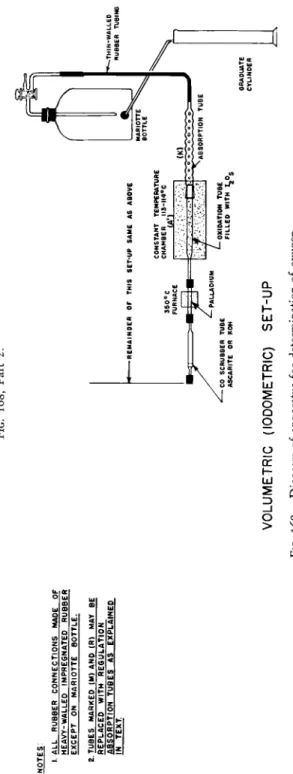
FIG. 168, Part 2. I. ALL RUBBER CONNECTIONS MADE OF HEAVY-WALLED IMPREGNATED RUBBER EXCEPT ON MARIOTTE BOTTLE. 2 TUBES MARKED (M) AND (R) MAY BE REPLACED WITH REGULATION ABSORPTION TUBES AS EXPLAINED IN TEXT -REMAINDER OF THIS SET-UP SAME AS ABOVE 350°C FURNACE CONSTANT TEMPERATURE CHAMBER MS-II4°C (A'l
-—THIN-WALLE RUBBE ABSORPTION TUBE -CO SCRUBBER TUBE ASCARITE OR KOH
OXIDATION TUBE FILLED WITH ^Og GRADUATE CYLINDER VOLUMETRIC (IODOMETRIC) SET-UP FIG. 168. Diagram of apparatus for determination of oxygen.
14. Oxygen 382
Apparatus
The pieces of apparatus required are shown in Figs. 168 and 169 described below. There are many points of similarity in this combustion train and that used for the determination of carbon and hydrogen, there being a bubble counter-U-tube, Ε (Fig. 1 6 8 ) , combustion apparatus (short movable sample furnace, C, and long furnace, B* extra long furnace, Λ (or constant temperature chamber, Λ'), absorption tubes, guard tube, and Mariotte bottle.
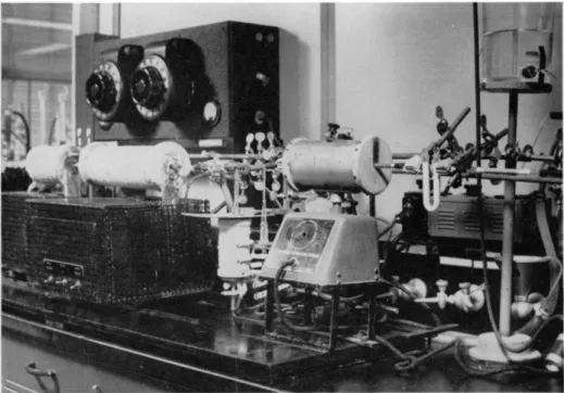
FIG. 169. Apparatus for determination of oxygen.
COMBUSTION APPARATUS
The apparatus consists of a long furnace and a short movable sample furnace.
In addition, some means, as described below, should be provided for heating to a high temperature the portion of the tube passing through the insulated walls of the furnaces.
In the past, most of the laboratories where the determination was being performed had furnaces custom-built in their respective machine shops. One of the chief problems connected with this determination has been the securing of suitable furnaces that stand up under the high temperature required. Since
* See footnote, p. 154, Chapter 7.
no recommended or tentative specifications have been published, it seems in order to describe the features (and some details) of those units which ap
peared to perform satisfactorily and for which details of construction have been published.
Walton, McCulloch, and S m i t h1 0 0 give complete details for the construction of their furnace in which the heating element is 9 0 % platinum-10% rhodium wire. Aluise et al.,5 described a long furnace5 7 which rides on a track and can be moved forward about 5 cm. to permit heating of that part of the reaction tube passing through the insulating walls. (Note: Where such pro
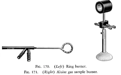
vision is not made, a ring burner9 3 of the type shown in Fig. 170 accom
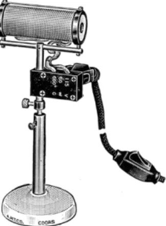
plishes the same effect. This directs flame points radially forward and is placed between the long furnace and the movable sample furnace or burner. ) A suitable commercially available gas sample b u r n e r2 , 9 3 is shown in Fig. 1 7 1 .
FIG. 170. (Left) Ring burner.
FIG. 171. (Right) Aluise gas sample burner.
The type of apparatus in use in the author's l a b o r a t o r i e s8 8'8 9'9 1 for the past ten years is shown in Fig. 169 and the details of construction are shown in Figs. 172a, 172b, 172c, and 172d. The photograph is that for a gravimetric procedure, although there is but slight modification for the volumetric (iodo- metric). The furnaces stand up under continuous heating at 1 1 2 0 ° C. for many months. (Note: The size pipe shown in the drawing ( % inch) is too small in internal diameter to accommodate tubes of the dimensions shown in Fig. 175. In addition, the length of the apparatus is too great for the above.
The tubes used by the author, which are custom made, are 9 mm. O.D., 6 mm.
I.D., and have an over-all length of approximately 107 cm., including the cap and stopcock.)
The heating elements are composed of Inconel pipe (nickel-chromium-iron- alloy, International Nickel Co., New Y o r k ) . This alloy is heat- and corrosion-
Fig. 112a, Fart 2, front elevation. PLATE 1.295 I.D COPPER BUSS BAR 1/4" THK x 2" WIDE COIL SPRING ALL DIMENSIONS IN INCHES FIG. 172a. Assembly for thermal decomposition apparatus for determination of oxygen—details of construction.
f ALLEN * SOCKET HD. SCREW S.S. ALUNDUM TUBE 2" I.D. X 3/8 " WALL
-I.OO< H-375H END DETAIL
_J t O . m CVJQ OJ Q ASBESTOS LAGGING END COPPER (SEE DETAIL) SILVER SOLDER 3/8 " IPS INCONEL PIPE TO END PIECE" ALUNDUM TUBE 3/4" I.D. X 1/8" WALL -1 ^.50 3/8" INCONEL PIPE TAPER SHORT FURNACE 1/2*- I 3/4 TAPER LONG FURNACE Ie - 3 1/2 ALL DIMENSIONS IN INCHES FIG. 172b. Heating elements for oxygen apparatus—details of construction.
14. Oxygen 386
FIG. 172C. Driving mechanism for oxygen apparatus—details of construction.
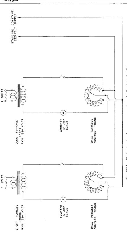
FIG. 172d. Electrical system for oxygen apparatus—details of construction.
14. Oxygen 388
ι—
resisting, nonmagnetic, and resistant to progressive oxidation and to intra- crystalline attack.
Constant voltage is supplied to the furnaces (long and short furnaces) t o obtain the constant temperature necessary during each determination.3'4 After several months of use, slightly higher voltages must be supplied through manipulation of the variable transformers in order to produce the same cur
rent consumption as when new. This indicates that under the conditions of operation, the resistance gradually increases. However, the constancy of tempera
ture in the short furnace is of no great importance.
Details of Construction12*91
The long furnace is made from a 2 kv.-amp. transformer with a 220-volt primary winding. This transformer was purchased without a secondary wind
ing, so that one of the desired size could be built. The secondary winding is made from 0.5 X 1.5 inch copper bus bar bent to fit the primary core. At some distance from the heating element connection is made to two 2 χ 2 χ 3 inch brass blocks through sections of I/4 χ 2 inch copper bus bar. The blocks tie the element to the transformer. Heat radiation is sufficient to prevent damage to the transformer, although air or water cooling may be employed. Expansion of the Inconel pipe on heating is permitted by the spring-like action of the connecting pieces ( 1/ 4 X 2 inch bus bars).
The heating elements are made from sections of % inch I.P.S. Inconel pipe, silver soldered to two copper ends bored out to fit the pipe. The copper ends are attached to copper plates using squeeze bolts. As the units operate under low voltage and high amperage, extreme care must be taken in making the connection of each joint. These ends and plates are also machined to hold concentric refractory tubes with air spaces between them, which act as in
sulators for the Inconel pipe. The outside of the unit is wrapped with asbestos tape. The element (Inconel pipe) of the long furnace is tapered from the inside of the copper end to within 3 inches of the center on both ends. This changes the resistance of the sections of the element so that the same temperature throughout may be maintained, and strengthens the center of the element. The taper runs from nothing in the center to 1° in 3.5 inches on each end. The short furnace is similar to the long, except that a one kv.-amp. transformer is used. During operation at 1120° C , the short furnace draws 620 amperes at 0.8 volt, and the long furnace, 4 8 0 amperes at 1.45 volts. (Keep the ammeters outside the influence of the magnetic field set up by the furnace circuits.)
Both furnaces are mounted on tracks with wheels. The long furnace is held in position by means of a tension spring, which permits it to be moved forward to the right several inches. The short furnace is mechanized. It travels forward 6 inches in 25 minutes and returns the same distance in 8 minutes.
14. Oxygen 390
When the short furnace comes in contact with the long furnace, it pushes the latter forward to the right about 2 inches before its motion is reversed. This permits heating of that part of the reaction tube passing through the insulating walls. When the short furnace then travels to the left, the tension spring causes the long furnace to return to its original position. The mechanization is accomplished by means of two screws fastened to the bottom of the short furnace, one for the forward motion and one for the backward motion. A toggle bolt screw action arrangement is used to change from one screw to the other at the extreme ends of travel. Power is supplied from a fractional horsepower, one r.p.m. gear head motor (Model SG-25 Flexo action motor) made by the Merkle-Korff Gear Co., 213 North Morgan Street, Chicago, Illinois.
Commercially available furnaces9 , 9 3 are shown in Figs. 90 and 125 (Chap
ters 7 and 9 ) , the latter requiring a special long furnace unit.
PREHEATER TYPE OF MICROCOMBUSTION FURNACE93
A small electric preheater type of microcombustion furnace (Fig. 1 7 3 ) is used in the nitrogen purification train. It maintains a section of copper turn-
FIG. 1 7 3 . Preheater type of microbustion furnace.
ings at 5 0 0 ° - 6 0 0 ° C , thereby converting any oxygen present to copper oxide compare Chapter 7, Tube Filling).
ADDITIONAL COMBUSTION FURNACES
For the gravimetric procedure, an additional combustion furnace (long sta
tionary furnace, only), of the type used for the Dumas determination, is required for maintaining the CuO tube at a temperature of 6 7 0 - 6 8 0 ° C .8 9'1 0 2
Another short sample furnace, L, capable of a temperature of 900° C , is
required to heat the reduced copper turning used to absorb sulfur compounds ( C S2 and C O S ) .1 2'1 5'6 5-6 6
HELIUM OR NITROGEN CYLINDER AND REDUCING VALVE
See above under Reagents. A safety valve of some type, which will blow off at a set pressure, should be used in addition to the reducing valve to prevent accidents.
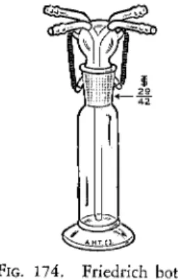
FRIEDRICH BOTTLE93
This is used as a pressure regulator for the system. This type of bottle (Fig.
174) is designed to act as either a pressure or partial vacuum regulator de
pending upon which of the set of tubes at the top are selected. For positive pressure, the two tubes which are connected to the vertically downward tube
FIG. 174. Friedrich bottle.
are used, the excess gas bubbles through the mercury in the body and leaves through the other set. [ I f constant partial vacuum is desired, the opposite set of tubes are used, the reduced pressure being kept constant by air (or gas) which is sucked downward through the vertical tube through the mercury.}
BY-PASS TUBE AND STOPCOCKS
The by-pass tube and stopcocks (Fig. 1 6 8 ) are used for backwash purposes, causing a stream of nitrogen to flow backward through the tube in order to exclude air when a sample is being placed in the decomposition tube. The by-pass tube may contain a coil section to give it flexibility to prevent break
age caused by strain.
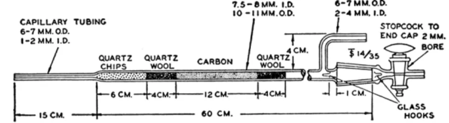
THERMAL DECOMPOSITION (COMBUSTION OR REACTION) TUBE93
The thermal decomposition (combustion or reaction) tube (Figs. 168 and 175) is made of clear fused quartz, Solar radiation grade.3 Attached to the main body of the tube is a heavy-walled capillary tip. At the other end is a Τ
14. Oxygen 392
1 4 / 3 5 interchangeable ground joint over which fits a cap provided with a stopcock. Near to the end, having the ground joint, is a side arm for connect
ing the nitrogen or helium supply. [Note: The tube used by Aluise et al.,5 had a body length of 600 mm. and a 150-mm. tip. The tubes commercially avail
able are shorter, having a body length of 550 mm. and a 100-mm. tip. The author has obtained excellent results with tubes having an over-all length of approximately 107 cm. (including the cap and stopcock), approximately 9 mm. O.D., and approximately 6 mm. I . D . ] Before being used, the tube should be cleaned by rinsing with hydrofluoric acid and then with water and dried.3
The tube is filled as shown in Fig. 175, with repeated tapping to avoid channeling during operation. (This figure shows the filling used by Aluise et al. If, however, a different size furnace is used, the carbon layer should
CAPILLARY TUBING 6 - 7 M M . 0 . D . I - 2 MM. I.D.
7.5 —β MM. 1.0.
10 - I I M M . O . D .
6-7MM.O.D.
2 - 4 MM. I.D.
/ STOPCOCK TO END CAP 2 MM.
BORE
FIG. 175. Thermal decomposition (combustion or reaction) tube, showing filling and details of construction.
be the same, but the amount of quartz chips and wool should be changed in the proper proportions.) It is extremely important that the carbon be in the section of the furnace at 1120° C. at all times.
REDUCED COPPER PURIFICATION TUBES
One nitrogen purification tube (Figs. 168 and 1 6 9 ) consists of a section of combustion tubing ( P y r e x1 6 No. 1720 glass) into which is packed about 10 cm.
of reduced copper turnings (compare Chapter 7 ) . This purification tube is mounted in the preheater type of furnace, and the copper turnings heated at 5 0 0 - 6 0 0 ° C , and placed before the bubble counter-U-tube in front of the thermal decomposition tube. A second tube, /, but prepared from quartz, is placed after the thermal decomposition tube and is heated to 9 0 0 ° C. Its function is to remove carbon disulfide and carbonyl s u l f i d e .1 2 , 1 5'6 5'6 6
COPPER OXIDE OXIDATION TUBE
A section of the standard Dumas combustion tube with tip (Fig. 98, Chapter 7 ) approximately 3 0 - 4 0 cm. in length, exclusive of the tip, is filled with about 25 cm. of copper oxide wire, similarly to the manner of filling the Dumas
tube, except that no reduced copper is used. This is placed in a long stationary furnace allowing 3 cm. to extend beyond the furnace as explained in Chapter 7.
The tube is maintained at 6 7 0 - 6 8 0 ° C. and is used to oxidize the carbon monoxide to carbon dioxide.8 9-1 0 2 (Fig. 168, Q.)
BUBBLE COUNTER-U-TUBE88'90'93
A bubble counter-U-tube is used in the purification train. It is identical to that used for the carbon-hydrogen determination8 8-9 0 (Fig. 120, Chapter 9 )
or it may have the ball member of a J 1 2 / 2 interchangeable ball and socket joint on both side arms.9 3 The unit is filled exactly as described in Chapter 9.
CARBON MONOXIDE SCRUBBER TUBE
The carbon monoxide scrubber tube (Fig. 168, R) is used for removing the halogens and sulfur present. Any type of drying tube may be used for this purpose and it is filled with the crushed potassium hydroxide pellets or with Ascarite—see above under Reagents.
ANHYDRONE ABSORPTION TUBE
A regulation absorption t u b e8 8-9 0 (Fig. 127, Chapter 9 ) is filled with Anhydrone exactly as the water absorption tube of the carbon-hydrogen determination.
(As an alternate, a U-tube filled with Anhydrone may be used—Fig. 168, M.) It is placed after the copper oxide tube, Q, before the carbon dioxide absorp
tion tube, N, the positions of the Anhydrone, Ascarite, and guard tubes being the same as in the carbon-hydrogen determination. The Anhydrone tube, how
ever, is a permanent part of the oxygen setup.
CARBON DIOXIDE ABSORPTION TUBE
A regulation absorption t u b e8 8-9 0 (Fig. 127, Chapter 9 ) is filled with Ascarite and Anhydrone, exactly as the carbon dioxide tube of the carbon-hydrogen determination (Fig. 168, N ) .
MARIOTTE BOTTLE8890
Same as used in Chapter 9.
GUARD TUBE8890
Same as in Chapter 9 (see Fig. 168, P ) .
GRADUATE CYLINDER
An ordinary 1000-ml. graduate cylinder is used for measuring the volume of gas passing through the system.
14. Oxygen 394
Assembling fhe Apparatus88 89
The various parts of the apparatus are connected either by means of paraffin- impregnated heavy-walled tubing, identical to that used in connection with the determination of carbon and hydrogen (see Chapter 9 ) , or by means of the various interchangeable ground joints. Assembly is begun at the connection to the source of nitrogen or helium and allowed to proceed connecting the various parts in their respective order—purification train, bubble counter-U- tube, thermal decomposition tube, by-pass, reduced copper tube, carbon monoxide scrubber, oxidation tube ( C u O ) , and drying tube. The carbon section of the thermal decomposition tube must be in the 1120° C. zone at all times. A slow stream of nitrogen (or helium) is passed through the system for about one hour with all units at room temperature, after which all sections are heated to their respective temperatures (purification train copper at 600° C , thermal decomposition tube at 1120° C , copper at 900° C , and copper oxide at 6 7 0 - 680° C ) . The inert gas is passed through for at least 2 days at the rate of about 10 ml. per minute (see Chapter 9 for method of determining rate by means of bubble counter). The carbon dioxide absorption tube is then attached to the system and to the guard tube (connected to the Mariotte bottle). With the arm of the Mariotte bottle slightly below the horizontal, the height of the mercury in the pressure regulator (Friedrich bottle) is adjusted so that 10 ml.
of gas per minute pass through the system (see Chapter 9 for determining volume) with all parts at operating temperatures. The rates at which the bubbles pass through the bubble counter and Mariotte bottle are recorded for reference just as done in connection with the carbon-hydrogen determination.
Best results are obtained by keeping the furnaces at all times at operating temperatures, even when not in use (compare Chapter 9 ) .
Procedure88 89
The rate of flow of nitrogen or helium through the system at operating tempera
tures (long furnace at 1120° C , copper combustion furnace at 900° C , copper oxide combustion furnace at 6 7 0 - 6 8 0 ° C , but short movable furnace at room temperature) is adjusted to 10 ml. per minute. The three-way T-stop- cocks, H, and H' (Fig. 1 6 8 ) are turned* so that nitrogen or helium is passed in the reverse direction through the thermal decomposition tube (reaction tube), G, and out through the stopcock of the cap, F. Enough sample is weighed into a platinum boat to contain 1.0-1.3 mg. of oxygen. ( I f the sample
* The stopcock, H, is closed to the reaction tube, G, and connects the source of nitrogen or helium with the by-pass tube. The stopcock, Η', is closed to the copper tube and connects the by-pass tube with the reaction tube, G.
is a volatile liquid, it is weighed in a capillary tube, preferably quartz, and inserted in a Coombs-Alber platinum sleeve or long platinum boat.) The cap, F, is removed and the platinum boat, containing the sample, is inserted and pushed to within about 8 cm. of the long furnace, B, with the aid of a platinum hook on the end of a glass rod. The cap, F, is replaced immediately, its stop
cock left open and the reverse flow of nitrogen or helium through the thermal decomposition tube (reaction tube), G, and out through the above stopcock, is continued for 20 minutes in order to expel all of the air that entered the system during the insertion of the sample.
The previously weighed Ascarite absorption tube is attached to the Anhy
drone absorption tube and the guard tube (connected to the Mariotte bottle).
The stopcock of the cap, F, is closed to the atmosphere and the three-way T-stopcocks, H and H' are turned* so that the nitrogen (or helium) will enter the thermal decomposition (reaction) tube, G, through its side arm. The stop
cock on the Mariotte bottle is opened and the nitrogen (or helium) allowed to flow through the entire system at the rate of 10 ml. per minute (making any necessary adjustment of the drainage tip of the Mariotte bottle—see Chapter 9 ) .
The movable sample furnace is heated to a temperature of about 1120° C , then brought up within about 4 cm. of the sample and the automatic drive put into operation. The sample is pyrolyzed gradually and the decomposition products are swept into the hot carbon in the portion of the tube inside of the long furnace. Approximately 25 to 30 minutes are required for the movable sample furnace to traverse the distance up to the long furnace. The long furnace is then moved forward to expose that portion of the tube protected previously by the insulating walls of the furnaces. [Note: A ring burner (Fig.
170) may also be used for the same purpose.] The short furnace is moved over and this portion is heated for about 5 - 1 0 minutes. The movable furnace is brought back and the long furnace returned to its original position. This insures complete pyrolysis of any material which may have condensed in the cooler portion of the tube. The movable furnace is allowed to cool, after which the sweeping out with nitrogen or helium is continued until approximately 700 ml. of gasf passes through the system during the course of the determina
tion from the beginning of the pyrolysis.
The Ascarite absorption tube is then removed, wiped, and weighed exactly as described in Chapter 9 on the determination of carbon-hydrogen.
A blank determination must be made by introducing an empty platinum boat into the reaction tube and duplicating the above procedure using 700 ml.
* The stopcock, H, is closed to the by-pass and connects the source of nitrogen or helium to the side arm of the reaction tube, G. The stopcock, H', is closed also to the by-pass tube and connects the reaction and copper tubes.
f Exactly the same amount is used for both the determination and the blank.
14. Oxygen 396
of nitrogen or helium.* The weight of carbon dioxide obtained from the blank determination is subtracted from that obtained during a regular determination.
A well-functioning setup gives a zero blank.
Calculation:
Factor:
Ο
W t . of C 02 X 0.3635 X 100
= 0.3635
= % Ο W t . sample
Example:
A 5.683-mg. sample gave 4.893 mg. of carbon dioxide
4.893 X 0.3635 X 100 3 1 . 3 0 % Ο 5.683
CLEANING DEPOSITED CARBON FROM REACTION TUBE88
After a number of determinations, a deposit of carbon forms on the inside wall of the thermal decomposition tube between the long and short furnaces.
This makes insertion and removal of the boat difficult due to poor visibility.
The deposit should be removed occasionally by the following procedure. With the entire setup assembled (absorption tube and Mariotte bottle attached) (Fig.
1 6 8 ) the stopcock, H, is closed to both the reaction tube, G, and the by-pass tube. The stopcock H' is closed to the by-pass and connects the reaction tube to the copper tube. The stopcock on the cap, F, is opened to the atmosphere, the arm of the Mariotte bottle lowered, and air is sucked through the reaction tube. The short movable furnace is heated to 1120° C. and moved over against the long furnace. The carbon deposit is burned off thusly in a matter of minutes. The stopcock on the cap, F, is then closed and the stopcock, H, turned to connect the reaction tube, G, with the supply of helium or nitrogen.
The inert gas is passed through the system overnight to free it of air after which it is again ready for use.
VOLUMETRIC (IODOMETRIC) METHOD
The volumetric (iodometric) method, too, is based on the thermal decomposi
tion of the sample in an inert gas and passage of the decomposition vapors over carbon at 1 1 2 0 ° C , at which temperature the equilibrium between carbon dioxide and carbon monoxide is shifted completely to carbon monoxide (see equations above under Gravimetric Method). The carbon monoxide is then converted to carbon dioxide by means of iodine pentoxide, iodine being formed
* Exactly the same amount is used for both the determination and the blank.
in the reaction which is titrated with sodium thiosulfate. The reactions in
volved are the following5-8 8:
Δ 1120° C.
Organic Ο > CO C
5CO + I205 = 5 C 02 + I2 I2 + B r2 = 2 IBr
2 I B r + 4 B r2 + 6 H20 = 2 H I Os + lOHBr 2 H I 03 + 10HI = 6 I2 + 6 H20 6 I2 + 1 2 N a2S203 = 12NaI + 6 N a2S406
Reagents
IODINE PENTOXIDE
Reagent grade of iodine pentoxide is required for the conversion of carbon monoxide to carbon dioxide with the simultaneous liberation of iodine. The particles used should not pass through a 100-mesh sieve.
SODIUM HYDROXIDE
A 2 0 % solution of reagent grade of sodium hydroxide in distilled water is used as the absorbent for the liberated iodine.
REDUCED COPPER TURNINGS
Same as used for Gravimetric Method.
POTASSIUM HYDROXIDE OR ASCARITE93
Reagent grade of potassium hydroxide pellets are crushed to 8- to 20-mesh size. They are tightly packed into the carbon monoxide scrubber tube for re
moval of acidic gaseous products formed during the thermal decomposition of substances containing halogens and sulfur (see below). Ascarite may be used in place of the potassium hydroxide.
ANHYDRONE93
This, together with Ascarite, is used in the bubble counter-U-tube (see Chap
ter 9 ) .
NITROGEN OR HELIUM
Same as for Gravimetric Method.
CARBON
Same as for Gravimetric Method.
14. Oxygen 398
QUARTZ WOOL AND QUARTZ CHIPS
Same as for Gravimetric Method.
PALLADIUM ON ASBESTOS
Palladium on asbestos ( 1 0 % ) is used for absorbing hydrogen. A palladium t h i m b l e1 1 , 1 2 may be used in place.
BROMINE
Reagent grade of bromine is used to oxidize the iodine to iodate previous to titration.
POTASSIUM ACETATE-GLACIAL ACETIC ACID SOLUTION
A 1 0 % solution of reagent grade of potassium acetate in glacial acetic acid is required.
SODIUM ACETATE SOLUTION, 20%
A 2 0 % solution of reagent grade of sodium acetate in distilled water is required.
FORMIC ACID
Reagent grade of formic acid, 9 0 % , is used to destroy the excess of bromine present after conversion of the iodine to iodate.
POTASSIUM IODIDE
Reagent grade of potassium iodide, crystals, is used to furnish the hydriodic acid needed for liberation of the iodine previous to titration with thiosulfate.
DILUTE SULFURIC ACID, 7 0 %
Dilute sulfuric acid, 1 0 % , is used to convert the potassium iodide to hydriodic acid.
STANDARD SOLUTION OF SODIUM THIOSULFATE, 0.01 Ν
This solution is prepared and standardized according to the directions given in Chapter 5.
STARCH INDICATOR
This is prepared according to the directions given in Chapter 5. (Aluise, Hall, Staats, and Becker5 suggest the use of an 0 . 2 % aqueous solution of amylose, G. Frederick Smith Chemical Company8 3 as the indicator. )
Apparatus
COMBUSTION APPARATUS
Same as for Gravimetric Method.
PREHEATER TYPE OF MICROCOMBUSTION FURNACE
Same as for Gravimetric Method.
ADDITIONAL COMBUSTION FURNACES
For the volumetric (iodometric) method, an additional small combustion furnace similar to the preheater type (Fig. 1 7 3 ) but controlled at a tempera
ture of 350° C. is required for heating the palladium on asbestos (or palladium) t u b e .1 1'1 2 Another short furnace, identical to that used for the gravimetric method is required to heat the reduced copper filling to 9 0 0 ° C. (for removal of C S2 and C O S ) .1 2'6 5'6 6
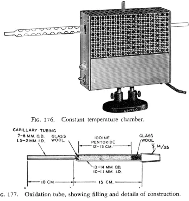
CONSTANT TEMPERATURE CHAMBER93
An electrically heated, thermostatically controlled, constant temperature chamber (Figs. 168 and 1 7 6 ) is used for maintaining the oxidation tube ( I205) at 1 1 3 ° - l l 4 ° C. for the purpose of driving out the liberated iodine. This is similar to the heating mortar used in the determination of carbon and hydrogen
(Chapter 9 ) .
FRIEDRICH BOTTLE \ NITROGEN (OR HELIUM) \ CYLINDER AND REDUCING VALVE I
REDUCED COPPER PURIFICATION TUBES I
BY-PASS TUBE AND STOPCOCKS \ Same as for Gravimetric Method.
THERMAL DECOMPOSITION ( (COMBUSTION OR REACTION) TUBE \
CARBON MONOXIDE SCRUBBER TUBE I
BUBBLE COUNTER-U-TUBE / PALLADIUM TUBE111289
This tube is used for absorption of hydrogen. It is placed between the carbon monoxide scrubber tube and the iodine pentoxide oxidation tube. It is prepared from a section of combustion tubing (Fig. 98, Chapter 7 ) . The palladium on asbestos is loosely packed in the tube for a distance of about 10 c m .8 9
The tube is heated in the small combustion furnace to a temperature of 350° C.
The palladium on asbestos is a cheap substitute for the palladium thimble
14. Oxygen 400
described by Campanile et al.,11 and Canales and Parks1 2, but if preferred, the latter should be used.
OXIDATION TUBE93
The oxidation tube (Fig. 1 7 7 ) is made of Pyrex1 6 glass. It has a heavy-walled capillary tip attached to the main body of the tube and at the opposite end is a '£ 1 4 / 3 5 interchangeable ground joint for attaching it to the absorption tube, Vigreux type (see below). The oxidation tube is filled with iodine pent-
FIG. 176. Constant temperature chamber.
CAPILLARY TUBING 7 - 8 M M . O.D. GLASS
1.5-2 MM. I.D. W00L
M / 3 5
FIG. 177. Oxidation tube, showing rilling and details of construction.
oxide, being held in place at both ends by plugs of glass wool. The packing of the iodine pentoxide must be done tightly to avoid channeling during operation. The oxidation tube is surrounded during operation by the constant temperature chamber. After being filled, a new tube should be heated for some days at 1 1 3 ° - 1 1 4 ° C. while nitrogen or helium is swept through to condition it.
ABSORPTION TUBE, VIGREUX TYPE93
The absorption tube (Fig. 1 7 8 ) is made of Pyrex1 6 glass. The main body has indented walls so that a large surface is provided. Attached to the one end of the main body is a heavy-walled capillary tip and at the other end is a
Τ 1 4 / 3 5 interchangeable ground joint which fits that on the end of the oxidation tube.
MARIOTTE BOTTLE88'90
This is the same as used for the carbon-hydrogen determination (Chapter 9, Fig. 1 2 9 ) .
GRADUATE CYLINDER
An ordinary 1000-ml. graduate cylinder is used for measuring the gas flow through the system.
14. £ 35
FIG. 178. Absorption tube (Vigreux type), left, showing attachment to oxidation tube, right.
AUTOMATIC BURETTE
An automatic burette of the type shown in Figs. 69 and 70 is used for titration of the iodine with thiosulfate.
GROUND GLASS-STOPPERED ERLENMEYER FLASK
An ordinary Pyrex 250-ml. ground glass-stoppered Erlenmeyer flask is used for the titration.
Assembling the Apparatus88 89
The various parts of the apparatus are connected either by means of paraffin impregnated heavy-walled tubing, identical to that used in connection with the determination of carbon and hydrogen (see Chapter 9 ) , or by means of the various interchangeable ground joints. Assembly is begun at the connection to the source of nitrogen or helium and allowed to proceed connecting the various parts in their respective order (see Gravimetric Method), thermal de
composition tube, by-pass, reduced copper tube, carbon monoxide scrubber tube, palladium tube, oxidation tube (I2O5), and absorption tube, Vigreux type.*
The carbon section must be in the 1120° C. zone at all times. A slow stream of nitrogen or helium is passed through the system for several hours with all the furnaces at room temperature. The preheater is heated to 5 0 0 ° - 6 0 0 ° C , the long furnace is gradually heated to 1 1 2 0 ° C , combustion furnace for reduced copper tube to 900° C , the furnace for the palladium tube to 350° C , and the constant temperature chamber is heated to 1 1 3 ° - l l 4 ° C. Nitrogen or
* The ground joint connecting the absorption tube, Vigreux Type, K, and the oxida
tion tube containing the iodine pentoxide, must be in the heated portion of the constant temperature chamber.
14. Oxygen 402
helium is passed through the system for some days. Then the Mariotte bottle is connected to the absorption tube, Vigreux type, which in turn is attached to the oxidation tube. (Note: No lubricant is used on this joint.) The pres
sure of the nitrogen or helium is adjusted carefully so that 10 ml. of gas per minute flows through the system when up to operating temperature. The rates at which bubbles pass through the bubble counter and Mariotte bottle under these conditions are recorded so that the same rate of flow may be obtained for all determinations (compare Chapter 9 ) .
Best results are obtained when the long furnace is kept at a temperature of 1120° C. overnight rather than at some lower temperature. Consequently, except when long periods of idleness are anticipated, the operation temperature should be maintained at all times (compare Chapter 9 ) .
P r o c e d u r e
5 8 8 8 9The rate of flow of nitrogen or helium through the system at operating tempera
ture (long furnace at 1120° C , constant temperature chamber at 1 1 3 ° - l l 4 ° C.,* but short movable furnace at room temperature) is adjusted to 10 ml.
per minute. The three-way T-stopcocks, H, and H', (Fig. 1 6 8 ) are turnedf so that nitrogen or helium is passed in the reverse direction through the thermal decomposition tube (reaction tube), G, and out through the stopcock of the cap, F. Enough sample is weighed into a platinum boat to contain 1.0-1.3 rng.
of oxygen. ( I f the sample is a volatile liquid, it is weighed in a capillary tube, preferably quartz, and inserted in a Coombs-Alber platinum sleeve or long platinum boat.) The cap, F, is removed and the platinum boat, containing the sample, is inserted and pushed to within about 8 cm. of the long furnace, B, with the aid of a platinum hook on the end of a glass rod. The cap, F, is replaced immediately, its stopcock left open and the reverse flow of nitrogen or helium through the thermal decomposition tube (reaction tube), G, and out through the above stopcock, is continued for 20 minutes in order to expel all of the air that entered the system during the insertion of the sample.
The tip of the absorption tube, Vigreux type, K, is immersed in the 2 0 % solution of sodium hydroxide and suction applied to All the tube almost to the ground joint. The alkali is allowed to drain off and the moistened ab
sorption tube attached to the oxidation tube (containing the iodine pentoxide), using a rotary motion so that the two joints are firmly sealed. (No lubricant is used.) This joint must be in the heated portion of the constant temperature chamber, A, so that all of the liberated iodine will be driven into the portion of the absorption tube moistened with sodium hydroxide. The Mariotte bottle
* Aluise3-4 has obtained good results with a temperature of 80° C.
t The stopcock, H, is closed to reaction tube, G, and connects the source of nitrogen or helium with the by-pass tube. The stopcock, H', is closed to the copper tube and con
nects the by-pass tube with the reaction tube. G.
is attached again to the absorption tube. The stopcock of the cap, F, is closed to the atmosphere and the three-way T-stopcocks, H and ¥L' are turned* so that the nitrogen or helium will enter the thermal decomposition (reaction) tube, G, through its side arm. The stopcock on the Mariotte bottle is opened and nitrogen or helium allowed to flow through the reaction tube, G, in the normal manner at the rate of 10 ml. per second.
The movable sample furnace is heated to a temperature of about 1 1 2 0 ° C , then brought up within about 4 cm. of the sample and the automatic drive put into operation. The sample is pyrolyzed gradually and the decomposi
tion products are swept into the hot carbon in the portion of the tube inside of the long furnace. Approximately 2 5 - 3 0 minutes are required for the movable sample furnace to traverse the distance up to the long furnace. The long furnace is then moved forward to expose that portion of the tube pro
tected previously by the insulating walls of the furnaces. [Note: A ring burner (Fig. 1 7 0 ) may also be used for the same purpose.] The short furnace is moved over and this portion is heated for about 5 - 1 0 minutes. The movable furnace is brought back and the long furnace returned to its original position.
This insures complete pyrolysis of any material which may have condensed in the cooler portion of the tube. The movable furnace is allowed to cool, after which the sweeping out with nitrogen or helium is continued until approximately 700 ml. of gasf passes through the system during the course of the determina
tion from the beginning of the pyrolysis.
The absorption tube, Vigreux tube, K, is disconnected from the Mariotte bottle and the oxidation tube in the constant temperature chamber. The con
tents of the absorption tube are rinsed with about 125 ml. of distilled water into a 250-ml. Pyrex ground glass-stoppered Erlenmeyer flask containing 10 drops of bromine and 10 ml. of the 1 0 % solution of potassium acetate in glacial acetic acid. The contents are stirred and then 10 ml. of the 2 0 % solution of sodium acetate in water is added. The excess bromine is destroyed by adding slowly with shaking 1 5 - 2 0 drops of 9 0 % formic acid using only what is needed to decolorize. The mixture is allowed to stand for about 5 minutes and then 0.3 gram of potassium iodide and 5 ml. of 1 0 % sulfuric acid are added. The contents of the flask are mixed by swirling and then titrated immediately with standard 0 . 0I N sodium thiosulfate using starch indicator.
A blank determination must be made by introducing an empty platinum boat into the reaction tube and duplicating the above procedure using 700 ml. of nitrogen or helium, f The volume of thiosulfate required for this blank
* The stopcock, H, is closed to the by-pass and connects the source of nitrogen or helium to the side arm of the reaction tube, G. The stopcock, H', is closed also to the by-pass tube and connects the reaction and copper tubes.
f Exactly the same amount is used for both the determination and the blank.
14. Oxygen 404
determination is the correction which is subtracted from the volume obtained in a regular one.
Calculation:
Factor:
1 ml. of 0 . 0 I N sodium thiosulfate is equivalent to 0.06667 mg. of oxygen ml. of 0.01N N a9S9O o (corrected) X 0.06667 X 100
Λ 2 2 3 1 / = % Ο
Wt. of sample
where ml. of 0 . 0 I N N a2S203 (corrected) = ml. for a determination — ml. for a blank.
Example:
3.518 mg. of sample required 17.00 ml. of 0 . 0 I N thiosulfate to titrate the liberated iodine. A blank determination required 0.30 ml. of 0.01N thiosulfate
.'. ml. of 0.01N N a2S203 (corrected) = 17.00 — 0.30
= 16.70 1 6. 7 0 X 0.06667 X 100
3.518 3 1 . 6 5 % Ο
CLEANING DEPOSITED CARBON FROM REACTION TUBE
See Gravimetric Method.
T A B L E 26
ADDITIONAL INFORMATION O N R E F E R E N C E S * RELATED TO C H A P T E R 14 In addition to the procedures described in detail in the preceding pages of this chapter, the author wishes to call to the attention of the reader the material listed in Table 26. (See statement at top of Table 4 of Chapter 1, regarding completeness of this material.)
Books General, miscellaneous, errors, etc.
Belcher and Godbert, 7 Aluise, Alber, Conway, Harris, Jones, and Clark, S. J , 13 Smith, 4
Grant, 31 Foreman, 25
Milton and Waters, 63 Gouverneur, Schreuders, and Degens, 29 Roth, 71, 72 Grube and Spiedel, 33
Steyermark, 88 Hinkel and Raymond, 35 . Kirsten, 4 8
ReV,eWS Kono, 4 9
Elving and Ligett, 24 K o n Q j S a t Q j S u 2 u k i ) a nd I s o b e 5 5Q
K a f n z2 6^2 7 Maylott and Lewis, 59
' . Moelants and Wesenbeek, 64
Unterzaucher, 94, 97 Λ .
Otting, 67
Collaborative studies Radmacher and Hoverath, 69 Jones, 44 Schôniger, 77
Steyermark, 86, 87 Unterzaucher, 9 5 - 9 7
* The numbers which appear after each entry in this table refer to the literature citations in the reference list at the end of the chapter.
T A B L E 26 (Continued) Traces
Walton, 99
Walton, McCulloch, and Smith, 100 Simultaneous determination of oxygen
and other elements Korshun and Bondarevskaya, 52 Apparatus
Aluise, Hall, Staats, and Becker, 5 Campanile, Badley, Peters, Agazzi, and
Brooks, 11 Canales and Parks, 12 Clark, S. J . , 13 Dundy and Stehr, 22 Garch and Valdener, 28
Gouverneur, Schreuders, and Degens, 29 Hinkel and Raymond, 35
Hintermaier and Griitzner, 36 Holowchak and Wear, 38 Kuck, 54
Maylott and Lewis, 59 Oita and Conway, 65 Oliver, 66
Siniramed and Manci, 82 Steyermark, 88
Steyermark, McNally, Wiseman, Nivens, and Biava, 91
Unterzaucher, 94, 95, 97 Willits and Ogg, 102 Zimmermann, 103, 104
Purification of carrier gas and gas used (He, N2, H2)
Burger, 10
Canales and Parks, 12 Imaeda, 41
Steyermark, 88
Thermal decomposition tube fillings Campanile, Badley, Peters, Agazzi, and
Brooks, 11 Colson, 14
Gouverneur, Schreuders, and Degens, 29 Hinkel and Raymond, 35
Imaeda, 43 King, 46
Korshun and Bondarevskaya, 53 Maylott and Lewis, 59
Thermal decomposition tube fillings (Con/.)
Oita and Conway, 65 Oliver, 66
Schoniger, 77 Unterzaucher, 94 Fluoro-compounds
Mâzor, 60 Rush, 73
Rush, Cruikshank, and Rhodes, 74 Thermal decomposition tube tempera
tures Colson, 14
Deinum and Schouten, 18
Gouverneur, Schreuders, and Degens, 29 King, 46
Korshun and Bondarevskaya, 53 Oita and Conway, 65
Oliver, 66 Steyermark, 88
Removal of sulfur compounds, inter
ference of sulfur compounds Canales and Parks, 12
Conway, 15 Dixon, 20
Kono, Sato, Suzuki, and Isobe, 50 Maylott and Lewis, 59
Oita and Conway, 65 Oliver, 66
Radmacher and Hoverath, 69 Interference from hydrogen
Campanile, Badley, Peters, Agazzi, and Brooks, 11
Canales and Parks, 12 Dixon, 20
Jones, 44
Various iodine pentoxide oxidation tube fillings
Campanile, Badley, Peters, Agazzi, and Brooks, 11
Canales and Parks, 12 Colson, 14
Gouverneur, Schreuders, and Degens, 29
14. Oxygen 406
T A B L E 26 (Continued) Various iodine pentoxide oxidation
tube fillings (Cont.) Grant, Katz, and Haines, 30 Imaeda, 42
Jones, 44 King, 46
Kono, Sato, Suzuki, and Isobe, 50 Oita and Conway, 65
Oliver, 66 Steyermark, 88 Unterzaucher, 94, 95, 98
Copper oxide oxidation tube filling Dixon, 20
Korshun and Bondarevskaya, 53 Willits and Ogg, 102
Use of hopcalite, M n 02, in oxidation tube
Deinum and Schouten, 18 Imaeda, 43
Spooner, 85
Use of mercuric oxide in oxidation tube
Deinum and Schouten, 18 King, 46
Gravimetric procedures Berret and Poirier, 8 Dixon, 20
Dundy and Stehr, 22 Jones, 44
Korshun, 51 Oita and Conway, 65 Radmacher and Hoverath, 69 Schutze, 7 8 - 8 0
Steyermark, 88 Willits and Ogg, 102 Zimmermann, 104 Volumetric procedures
Burger, 10
Campanile, Badley, Peters, Agazzi, and Brooks, 11
Canales and Parks, 12 Deinum and Schouten, 18 Hinkel and Raymond, 35 Jones, 44
Volumetric procedures (Cont.) King, 46
Lacourt, 55 Lee and Meyer, 56
Radmacher and Hoverath, 69 Renard and Jadot, 70 Steyermark, 88 Unterzaucher, 94, 96
Manometric, gasometric procedure Holowchak and Wear, 38
Physical chemical technique Harris, Smith, and Mitchell, 34 Amperometric, potentiometric, con-
ductometric methods, automatic titration
Canales and Parks, 12 Drekopf and Braukman, 21 Ehrenberger, Gorbach, and Mann, 23 Determination in presence of metals
Hoekstra and Katz, 37 Huber, 40
Takahashi, Kawane, and Mitsui, 92 Absorption, chromatographic method
Pietsch, 68
Colorimetric method
Walton, McCulloch, and Smith, 100 Fusion methods
Lee and Meyer, 56 Sheft and Katz, 81 Isotopic oxygen
Anbar, Dostrovsky, Klein, and Samuel, 6 Dahn and Moll, 17
Grosse and Kirshenbaum, 32 Hydrogénation methods
Dinnerstein and Klipp, 19 Kirner, 47
Maylott and Lewis, 59 Meulen, ter, 61
Meulen, ter and Heslinga, 62 Russell and Fulton, 75 Russell and Marks, 76
Smith, Duffield, Pierotti, and Mooi, 84