CRYOGENIC TANKAGE FOR CHEMICAL SPACE POWER SYSTEMS 1
James E. Bell and William H. Reid c Beech Aircraft Corporation
Boulder, Colorado ABSTRACT
Technical data pertaining to storage of cryogenic pro- pellants for space-vehicle auxiliary power systems are pre- sented. These data describe principally two methods of stor- ing and expelling hydrogen and oxygen propellants· Tank sizes and weights are analyzed for various type missions, resulting in comparative values which are suitable for preliminary de- sign. Pressurization methods for expelling the propellants are presented in schematic form with recent test results veri- fying the predicted characteristics. Finally, basic conclu- sions for space-mission cryogenic tankage are presented.
Tank System Requirements
Studies conducted by several agencies indicate that hydrogen-oxygen propellant systems offer significant advan- tages over other propellants for short-time space missions.
The advantages include weight savings as reflected by ex- cellent specific fuel consumption, and inherent ability of the hydrogen to absorb large heat inputs.
The minimum-weight tank design cannot be made without knowledge of environmental conditions and operating require- ments. There is no one optimum tank system; rather, an optimum design for each set of conditions. For proper de- sign and analysis, the following information should be known.
A. Usable quantities of propellants required and use rate as a function of time. This is determined from power generating and cooling system loads.
B. Tank system temperature environment as a function of time. Two main factors affect the temperature: ex- ternal heat sources such as aerodynamic heating or solar 1. Submitted for publication to the American Rocket Society,
January 17, 1961.
2. Airborne Cryogenics System Group.
and planetary radiation which involves orbital altitude and eclipse periods : internal heat sources resulting from combustion chambers, alternators, and electronic equipment·
C. Total mission time.
D· Maximum acceleration through each axis of the vehicle.
E. Required propellant pressure.
F. Net positive suction head requirements.
G· Vehicle dimension and geometry for tank installation.
ÏÏ. Type of mission, i.e., earth orbit and re-entry, space probe, etc.
I. Operating safety factors, and reliability desired.
J. Available power supply for tankage controls.
The detailed information required for the design of a minimum-weight cryogenic tank system is difficult to obtain in the early stages of vehicle design. Therefore, final de- sign of the cryogenic tankage should be delayed until these factors are known, or the system should be overdesigned and modified as information becomes available.
Principles of Storage and Expulsion
The storing and expelling of cryogenic fluids during space missions requires several basic considerations which are a function of the type of mission. Initially, all cryo- genic fluids require special containers to maintain the fluid in a desired state due to the low temperatures and low criti- cal pressure points. For space flight, the containment of the fluids creates additional problems due to the zero gravi- ty and temperature environments.
During the time in which a space vehicle is in a zero gravity flight path, special provisions must be made to in- sure delivery of the required mass flow rates of the respec- tive propellants to their ultimate end destinations (i.e., heat exchanger, corabustor, reaction control jets, etc. ). If the propellants are maintained in their tanks at pressures below their critical pressure, both gas and liquid may exist.
The introduction of a zero "g" condition will then cause ran- dom dispersal of the liquid and the vapor within the tank.
This dispersal of different density fluids creates a problem in determining methods of propellant metering or pumping. In the case of cryogenic propellants, this situation is compli- cated further by the fact that the ratio of vapor to liquid will always tend to increase (due to evaporation) unless re- frigeration means are employed.
There are four basic methods of tankage under zero "g"
environment to provide single-phase fluid delivery to the feed system·
A. The creation of an artificial force field by spinning or accelerating the tank will separate the denser fluid.
B. Utilizing insulated capillary tubes to provide isenthal- pic expansion (providing a temperature and pressure drop) to liquid entering the feed system, resulting in single- phase gas feed and recuperation of latent heat as re- C. Subcritical propellant storage with positive expulsion
methods utilizing a bladder, diaphragm, piston, or other device which will positively separate the liquid from the pressurization gas.
D. An overcritical pressure propellant system which insures a single-phase fluid supply under all environments.
This document considers technical data pertaining only to the latter two tankage systems.
Positive Expulsion System
A positive expulsion system is defined as a system in which the liquid is positively displaced from the tank by
some mechanical means. A separate bladder is usually used to collapse about the liquid as expulsion takes place. The object of positive expulsion techniques is to always maintain liquid-vapor separation, thereby assuring single-phase liquid flow to pumps or meters.
Tank operating pressure is always less than the critical pressure of the liquid. Figure 1 illustrates a typical posi- tive expulsion tank system.
In applying the positive expulsion method to cryogenic systems, the following special considerations are in order:
Insulation must be very effective to maintain the liquid
in single-phase condition. The operating pressure used must he high enough, and the heat input low enough, to maintain the liquid in a subcooled state. Equilibration of the liquid temperature during zero "g" by forced mix- ing is a probable requirement to prevent boiling.
To minimize heat transfer to the liquid, the pressuriza- tion gas temperature should not be greater than the liquid temperature, and the gas must not be condensable at liquid temperature.
Design Principles
A. Tank Sizing: Determine the -weight of fluid required, including -whatever margin is required for possible mis- sion changes. Two per cent is added to this quantity to allow for liquid trapped in the folds of the bladder.
Volume is determined from the fuel load and the fluid density at fill· At one atmosphere pressure, liquid- hydrogen density is k.k-3 lb/ft3 and LOX density is 71.2 lb/ft3. (Reference 1)
B. Heat Transfer and Insulation: The primary consideration here is determining the lightest insulation system for the allowable heat flux into the fluid stores and the particular temperature environment.
In positive expulsion systems boiling must be prevented by maintaining the liquid in a subcooled state. The liquid is loaded at about one atmosphere pressure and saturation temperature. It is then pressurized and thereby subcooled. The allowable heat leak during the mission is that heat necessary to raise the liquid tem- perature to the saturation temperature at the operating pressure or to a minimum NPSH value. A weight trade-off
study is made by summing the "weight of the insulation required to limit the heat leak to the allowable and the weight of the tank skin as required to contain the pres-
sure (see below). An optimum operating pressure and in- sulation system is determined by finding the minimum weight.
A number of insulation systems are available for posi- tive expulsion tanks. These include:
A rigid outer shell with the tank suspended on cables, and the vacuum space filled with a multi- ple layer insulation (Ref.2) in unloaded condi- tion.
A nonrigid outer shell encapsulating and "bearing upon a multiple-layer insulation or combination of insulations such as: ceramic fibers over glass fibers and radiation-shielding insulation·
Expulsion Bladder Design: The following rules summarize design experience for cryogenic expulsion bladders:
1·. A spherical bladder in a spherical tank is the optimum shape·
2· The bladder, when expanded, must closely fit the tank.
3· The bladder must not be bunched or· gathered; it must be fabricated to shape·
h* Tank walls must be smooth and free from irregu- larities·
5· The best bladder material found to date is elec- trical grade Mylar (Ref· 3) film· The bladder should consist of several independent layers·
(Ref· h)
Pressurizing and Expulsion Gas System: Figure 1 illus- trates the most reliable system for storage and utili- zation of helium gas used in expulsion of the cryogenic liquids· Helium gas is stored at liquid-hydrogen tem- perature and about 3000 psia in a small internal tank·
As fluid is withdrawn from the tank, a pressure regula- tor releases helium gas and maintains pressure·
For tank pressures between 20 and kO psia, helium gas weight to expel liquid will be 7 to 10$ of weight of hydrogen expelled· (Ref· 5)
Tank Design: The inner tank (the pressure vessel) thickness is determined by two criteria:
1· Stress
2· Minimum fabricable gauge of the metal under consideration·
In the case of spherical tanks, the first analysis can utilize the following:
t = 2S(F.S.) (Ref· 6>
Where
t = Minimum Thickness P = Tank Maximum Pressure
S = Allowable Stress at Maximum Possible Tank Temperature
R = Tank Radius F.S. = Factor of Safety
For detailed analysis of such problems as discontinuity stresses around the neck and point loads at the cable attachment points, refer to texts such as Refs· 6 and 7·
Performance
A liquid-hydrogen positive expulsion system was built as part of an effort to develop reliable bladders (Ref. 5)·
A spherical, unsilvered glass dewar was used for the tests, and bladders of a variety of materials "were fabricated·
The bladders were designed under the concepts discussed above. Material combinations such as Mylar film laminated to dacron and orlon felt and multiple unbonded plys of plas- tic film were evaluated. (Ref. h)
The most successful bladder had no leaks at the conclu- sion of tests with 79 full cycles of liquid-hydrogen filling and expulsion. It consists of three unbonded plys of l/2 mil aluminized Mylar. Figures 3 ana ^ are photographs of the test apparatus and control panel.
The success of this expulsion system is due not only to the physical properties and construction method of the blad- der, but also to the bladder being the same size and shape as the dewar, and to the smooth inner surface of the dewar.
The tests show that positive expulsion systems can be used for cryogenic storage. However, it has worked only in the rather gentle environment of the laboratory and needs to be proven under conditions simulating the severe condi- tions of acceleration, vibration, and shock of actual flight.
Overcritical System
An overcritical system is defined as a system in which the fluid pressure within the tank is greater than critical, and the tank is filled with a uniform high-density fluid.
The advantage of an overcritical system is that the fluid can be withdrawn from the tank regardless of gravity condi-
tions, and the system is reliable with no boost pumping or mechanical means of expulsion· The fluid density -will be the same throughout the entire volume at any time, and the system is assured of the proper mixture ratio by weight·
One problem in the design of such a system is that the thermodynamic properties data of the high-density over- critical fluids are limited (particularly for oxygen) which results in limited accuracy in the theoretical analysis·
Also, the high pressure necessitates relatively thick-skin gauges that impose a structural skin-weight penalty· In some cases, this weight penalty is offset by the elimination or minimization of pumps, valves, and mechanical expulsion equipment·
For overcritical systems, the pressure and propellant requirements and variable propellant use rates create a heat transfer problem that lends itself to only an approximate solution· The basic problem on overcritical tanks is to maintain the required working pressure within the specified limits. To accomplish this purpose, either the fluid in the tanks must be pressurized by adding heat, gas must be added during certain time increments of the mission, or a mechani- cal means of reducing the volume would be required· Where available power is limited, the most feasible method of maintaining tank pressure is to add hot gas when the tank pressure drops to a minimum limit·
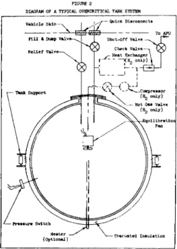
Figure 2 is a diagram of a typical overcritical system.
Heat can be added to the fluid by means of electrical resist- ance heaters in the tank or by added hot gas. Hot gas can be obtained from an external heat exchanger in the vehicle system and forced into the tank by means of a small compres- sor in the gas line. Equilibration fans should be installed in the tank to circulate the fluid, thus raising the bulk temperature more evenly and improving response character- istics. In either case, excessive pressure rise must be con- trolled by accurate heat input regulation.
Design Principles
A. Tank Sizing: Supercritical tanks are sized by deter- mining the usable quantity of propellant required and the residual gas weight from Figures 6 and 7· Residual gas weight is determined by considering the following factors :
Minimum useful density of gas for heat exchanger and combustors
Maximum temperature of gas allowable Maximum available heat for pressurization Volumes are determined from initial temperature, pressure, and density (Refs. 1, 8, 9, and 10). Typical
initial temperatures used are U5°R for hydrogen and 190°R for oxygen. Typical final temperatures are 120°R for hydrogen and 3Ô0°R for oxygen.
Thermal Requirements: Overcritical tanks utilize heat transfer to the stored fluid to maintain pressure as fluid is "withdrawn. During the mission, temperature in- creases, fluid density decreases, and pressure remains essentially constant.
The heat necessary to maintain pressure is:
4 = Ρφ) M
Where Q is the heat flux required to maintain pressure /° is the density of the fluid in the tank
M is the mass flow rate out of the system
The heat may be added in the form of hot gas, and the mass of hot gas may be obtained by substituting:
M (hot gas ) Δ h for Q. The A h is the difference in enthalpy between the hot gas and the fluid in the tank, and M (hot gas) is the hot gas mass flow rate.
This expression assumes virtually instantaneous re- sponse and has been applied successfully for preliminary design.
Figure 8 shows the heat input rate required to maintain pressure in hydrogen and oxygen tanks per pound of fluid extracted plotted against per cent of loaded fluid remaining in tank. Figure 9 shows the total heat input required to maintain pressure. The values for ox- ygen are approximate only.
Heat Transfer and Insulation: The total heat leak al- lowable in overcritical systems is much larger than in positive expulsion systems; however the rate of allow-
able heat leak is dependent upon the fuel and use rate.
The heat 'leak must never exceed the heat required for maintaining pressure in the tank; and for a detailed
analysis, mission environmental temperature and fuel use rate are necessary·
D. Tank Operating Pressure: The critical pressure of hy- drogen is 12·7 atmospheres and 50·1 atmospheres for oxy- ygen· Systems should he designed to operate above these pressures but as near to them as the fuel demand and pressure control responses -will allow. For instance, ant attitude control system, which requires large flow rates for short-time periods, will require a higher operating pressure in the tanks than a system that uses fuel at a steady, predictable rate.
E. Tank Design: Overcritical systems utilize the same principles of pressure vessel design as the positive expulsion systems.
F. Hydrogen Properties: The thermodynamic properties of equilibrium hydrogen have not yet been published, but it is believed that the FVT data will not vary from that of normal hydrogen by more than three per cent (See Refs. 9 and- 11 for data). During the operation of over- critical hydrogen tanks, it is possible for the equilib- rium composition of the hydrogen to change as the fluid temperature rises. Part of the parahydrogen can recon- vert to orthohydrogen (Ref. 12) and thereby increase the heat required to maintain pressure. If this occurs, it results in a slight increase in the heat sink capacity of the hydrogen and increases the required capacity of the pressurizing system.
Performance
A hydrogen expulsion system operating at pressures greater than critical pressure has been successfully tested.
The test apparatus is shown in Figure 5· Pressure has been maintained over a wide range of fluid use rates by the addi- tion of heat. Both electrical heaters and hot gas addition have been used with equal success. Flow rates of fluids out of the system can be changed by a factor of ten and stabi- lized within two seconds.
Figure 10 shows results of two tests: one using an electrical heater and one using open-loop gas for pressuri- zation. The dewar holds approximately 17 pounds of hydrogen.
Heat input was manually controlled by an operator observing a pressure gauge. Note the small pressure fluctuation.
The heat required to maintain pressure in the tank has
"been analyzed theoretically, and test results agree -with theory with a maximum error of 10$ in the twenty test runs made to date·
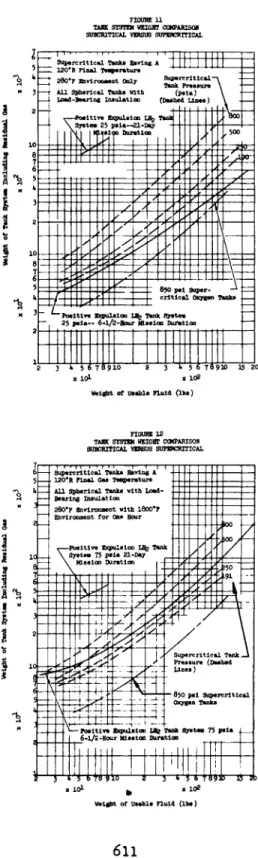
Figures 11 and 12 show results of a study of tank system weights. The systems were designed rather conservatively with allowable stress in the pressure vessel taken at l60°F and a maximum working stress of F^u/l#995· The total system weights include all necessary components and the weight of residual gases·
The tanks in Figure 11 were designed to withstand a con- tinuous 280°F temperature environment, and those in Figure 12 were designed for 280°F with a one-hour l800°F re-entry·
Conclusions
The cryogenic storage and expulsion systems described in this paper offer two available methods for supplying pro- pellants to chemical power systems during space missions·
Positive expulsion of subcritical fluids is considered very useful where the vehicle compartment temperatures are less than 280°F and the space mission is less than eight hours. In cases where the storage tanks must withstand an environmental temperature of l800°F for short durations (re- entry), the overcritical storage system offers more signifi- cant weight savings, particularly if the propellant is con- tinuously used·
Figures 11 and 12 compare the two types of tankage sys- tems for the 280°F and l800°F- environments. It is interest- ing to note that the overcritical system weight will remain relatively unchanged for unlimited mission times, while the positive expulsion system becomes prohibitively heavy for even 21-day missions.
Finally, the present-day development status favors the overcritical storage system because of the inherent simplic- ity of operation, reliability, and availability of all the necessary system components.
REFERENCES
1. Johnson, V· J·, Editor, A Compendium of the Properties of Materials at Low Temperature, Wright Air Development
Center Contract No. 33(6l6)-58-4, National Bureau of Standards, Cryogenic Engineering Laboratory, Boulder, Colorado, December 1959·
Timmerhaus, K. D., Editor, Advances in Cryogenic Engi- neering, Vol. 5, Proceedings of the 1959 Cryogenic Engineering Conference, Pages l8l to 221.
Registered Trade Mark of E. I. du Pont de Nemours &
Company (inc. ).
Spieth, C. W., Et Al, Development of Positive Expulsion Systems for Cryogenic Fluids, Phase I, AFFTC TR 60-70, USAF, Air Research and Development Center, Edwards AFB, California, Dec. i960.
Simmons, J. T·, The Physical and Thermodynamic Proper- ties of Helium, TR D-9027, W. R. Whittaker Co. Ltd, 915 No. Citrus, Los Angeles 38, California, 1 July 1957·
Timoshenko and Woinowsky-Kreiger, Theory of Plates and Shells, McGraw-Hill Book Co., New York, 1959, 2nd Edi- tion.
Hetényi, M., Beams on Elastic Foundation, The University of Michigan Press, Ann Arbor, 19^7·
Hilsenrath, Et Al, Tables of Thermal Properties of Gases, National Bureau of Standards Circular %h, U. S. Govern- ment Printing Office, Washington 25, D. C , November 1, 1955.
Woolley, Scott, and Brickwedde, Compilation of Thermal Properties of Hydrogen in Its Various Isotopic and Ortho- Para Modifications, National Bureau of Standards RP 1932, U· S. Government Printing Office, Washington 25, D. C , 19^8.
Tkachenko, E· A., "Pressure-Density-Temperature Relation- ship of Liquid 02," ARS Journal, Vol. 30, No. 6, June I960, Pages 556 to 558.
Scott, R. B., Cryogenic Engineering, D. Van Nostrand Co., Princeton, 1959·
Hydrogen Handbook, AFFTC TR 6O-I9, USAF Air Research and Development Center, Edwards AFB, California, April i960·
FIOURE 1
DIAGRAM OF A TYPICAL POSITIVE EXPULSION SYSTEM
FIGURE 2
DIAGRAM OF A TYPICAL OVERCRITICAL TANK SYSTEM
Vehicle Skin
Fill S> Duop Valve- Relief Valve-
Quick Disconnects
Shut-Off V a l v e — ^ Γ*""
Check Valve—. yÇ - Heat Exchanger \ |
I(H. only) \
ïquilibrationl
Evacuated Insulation
FIGURE h
POSITIVE EXPULSION CONTROL PANEL
FIGURE 3
POSITIVE E*RJLSI0N SYSTEM TEST APPARATUS
FIGURE 5 OVERCRITICAL SYSTEM
TEST APPARATUS
Percent of Loaded Weight oi 0. Fercaining in Tank at 2nd of Mission -~<f> Percent of Loaded Weight of Hg Remaining at End of Mission ~ i> /
1 1 I 1,100 . 1,000 N 900 Γ
8 9
k I
§3 s 1I
1
3 a·ί
5 5S 8 8 8 / / // ' / /
P // I
^ / /
§ / /-
8 o ί ^^§ o
80 5> üö~
Percent of Loaded Weight of Fluid ReMinlne ~ #
FIGURE 9
TOTAL BEAT BIPUT REQUIRED TO EXPEL ORE FOURD 07 FLUID AT CORSTART PRESSURE VS. PBRCERT OF LOADED WEIGHT
OF FLUID REMAIRIRD AT EID OF KD38IOR lUO
£
I * 1
f
T 60
1
3
I
£ 20
1
UL
//χ Γ S δ \ ö CC 300 pela /
/ /
900 pela .
2C
77Ί
/ / /250 pala
Oxygen
736 pela
0 Percent of Loaded Weight of Fluid Remaining at End of Kiaalon ·— ί
SPACE POWER SYSTEMS
£ "U
o oovo ^t CVJ o • · · · · H O O O O Mass Flow Rate Pounds/Mtnute o o o o o o «EIS a^ Tank Pressure PSI Gauge iA4 c^W H
Heat Input BTU/Seconds
610
FIGURE 11 TAHK SYSTEM WEIGHT C0MPARISOJI SUBCRITICAL VERSUS SUPERCRITICAL
S u p e r c r i t i c a l Tanka Having A I 1 I I 1 M
! 120*R Final Température
280'F Environment Only ï îPîr^t i C*1~ Tank Preaaure All Spherical Tanks With (psla) Load-Bearing Insulation (Dashed Lines)
v—Positive Expulsion LEg Tanld
\ Systesi 25 psia—21-Day ' ' I |\1 I I Mission Duration
' P o s i t i v e Expulsion LBg Tank Systea 25 psia— 6-l/2-Hour Mission Duration
3 i 5 6 7 8 9 1 0 2 Y x l O *
Weight of Usable Fluid (lbs)
\ 5 6 7891D Ï 5 2 0 X102
FIGURE 12 TASK SYSTEM WEIGHT COMPARISON SUBCRITICAL VERSUS SUPERCRITICAL
Welgbt of Usable Fluid (lbs)