Contents lists available atScienceDirect
Thin Solid Films
journal homepage:www.elsevier.com/locate/tsf
The e ff ect of various substrates and catalyst layer deposition on the incorporation of nitrogen into carbon nanotube forest structures
Anna Szabó
a, Tamás Gyulavári
a, Zsejke-Réka Tóth
a,b, Zsuzsanna Pápa
c, Judit Budai
c, Klara Hernadi
a,⁎aDepartment of Applied and Environmental Chemistry, University of Szeged, Szeged 6720, Hungary
bNanostructured Materials and Bio-Nano-Interfaces Center, Interdisciplinary Research Institute on BioNano-Sciences, Babeș–Bolyai University, Cluj-Napoca 400271, Romania
cDepartment of Optics and Quantum Electronics, University of Szeged, Szeged 6720, Hungary
A R T I C L E I N F O
Keywords:
Carbon nanotubes
Catalytic chemical vapor deposition Nitrogen
Pulsed laser deposition Dip-coating
Scanning electron microscopy and transmission electron microscopy
A B S T R A C T
The incorporation of nitrogen into carbon nanotubes (CNTs) might increase their conductivity that can further enhance their excellent properties which is a very important issue nowadays. The current research focused on the fabrication of nanotube forestsvia catalytic chemical vapor deposition method and the investigation of nitrogen incorporation into carbon nanotubes on the surface of various substrates such as aluminum, titanium and silicon. Also, this study dealt with different catalyst layer deposition techniques in order to simplify the production of CNT forests. Besides, more complex layer construction methods such as pulsed laser deposition and dip-coating were also applied since they can influence the incorporation of nitrogen into carbon nanotubes as well. Samples were analyzed by scanning electron microscopy, transmission electron microscopy, energy- dispersive X-ray spectroscopy, and Raman spectroscopy.
1. Introduction
Nowadays, vertically aligned carbon nanotube forests play an im- portant role in many studies due to their 3D structure and outstanding physical and chemical properties. A research team in Beijing succeeded suly in the production of carbon nanotube (CNT) forestsviacatalytic chemical vapor deposition (CCVD) synthesis technique[1], which was later proved to be the only method suitable to achieve such structures.
A very important step in the production of carbon nanotube forests is the deposition of the catalyst layer which can be easily carried out these days, for exampleviapulsed laser deposition (PLD)[2], spray-coating [3]and dip-coating[4]. As catalytic materials most commonly Fe[5], Co[6], Fe-Co[7–9]and Ni[10]salts are used. The quality of substrates in the production of carbon nanotube forests also plays a crucial role, namely the catalyst adhesion ability onto the substrate surface might strongly influence the features of the final product[11]. The most commonly used conductive substrates are titanium [12], aluminum [13], stainless steel[14]and copper[15], which are easy to apply in various electronic devices, however, SiO2[16]is also frequently used.
To further enhance the excellent electrical properties of CNTs, they are often doped with N and B. In the case of N-doping, they exhibit n- type behavior [17], which may play an important role in their
application. Nowadays, the doping process can be carried out in many ways,e.g.with injection[18], water-assisted approach[19], pyrolysis method[20], horizontal injection[21], nitrogen plasma doping[22], plasma assisted N-doping[23], electron cyclotron resonance [24], or bubbling [25]. The structure of CNTs is (largely) dependent on the doping process which can influence the diameter of carbon nanotubes, often together with the appearance of bamboo structure in carbon na- notube walls. NH3is the most commonly used material to dope carbon nanotube forests[26], but other nitrogen-containing compounds such as acetonitrile [19], ethylenediamine[27], 4-tert-butylpyridine [28], and palm oil[29]are also proved to be effective to incorporate nitrogen into carbon nanotube structures. Due to the fact that the application of on silicon substrate usually results in high quality carbon nanotube forests, SiO2is the most widely used substrate during N-doping nowa- days[30]. However, by the application of conductive substrates, the outstanding electric properties of CNT forests could be utilized much more effectively. In spite of this fact, there are only a few examples in the literature for the growth of N-doped CNT forests,e.g.on stainless steel[31]. Nevertheless, more and more successful attempts have al- ready been published about the synthesis of undoped CNT forest structures on conductive substrates[32], which provide a good basis for the fabrication of their doped counterpart. Doped (vertically aligned)
https://doi.org/10.1016/j.tsf.2020.138194
Received 20 January 2020; Received in revised form 5 June 2020; Accepted 19 June 2020
⁎Corresponding author.
E-mail address:hernadi@chem.u-szeged.hu(K. Hernadi).
Available online 20 June 2020
0040-6090/ © 2020 The Authors. Published by Elsevier B.V. This is an open access article under the CC BY-NC-ND license (http://creativecommons.org/licenses/BY-NC-ND/4.0/).
T
CNTs are often prognosticated to be promising candidates to form in- tegral parts of fuel cells[33]and sensors[34].
In this paper the influence of different substrates and layer-building techniques both on the growth of CNT forests and on the incorporation of nitrogen into carbon nanotubes was investigated. The major goal was to build CNT forest onto a conductive substrate and simultaneously increase the nitrogen incorporation into their structure, thus utilizing the increasing conductivity of these N-doped patterns, which can be further enhanced by the conducting substrate.
2. Materials and methods 2.1. Materials
The substrates applied for the synthesis of carbon nanotube forests were aluminum (99.99%, VWR), titanium (99%, VWR) and silicon (<100>, P-type, Sigma). During the fabrication of the catalyst layer with the pulsed laser deposition (PLD) method, aluminum oxide (WRS Materials Company), iron(III) oxide (99.998%, Sigma-Aldrich) and co- balt(II) oxide (99.99%, Sigma-Aldrich) were used as target materials, while for the dip-coating method, cobalt (cobalt(II) nitrate hexahy- drate, 99% (Sigma-Aldrich)), iron (iron(III) nitrate nonahydrate, 99.9%, Sigma-Aldrich) and absolute ethanol (99.8%, VWR) as solvent were used. Nitrogen (99.995%, Messer), hydrogen (99.5%, Messer) and ethylene (>99.9%, Messer) were used as synthesis gases. During the synthesis tripropylamine (TPA; ≥98%, Sigma-Aldrich) and acetone (Ac; a.r., Molar Chemicals Kft.) were used as nitrogen sources in 3:7 ratio.
2.2. Catalyst preparation
During the experiments two catalyst coating techniques, PLD and dip-coating methods were used. For the silicon substrate the PLD method, for the aluminum substrate the dip-coating method, and for the titanium substrate both methods were applied to build the catalyst layer.
During the PLD method proper mixture of Fe2O3and CoO was used as target materials for the catalyst layer, and as support layer Al2O3was also deposited onto the surface of the substrate. The pellets (m= 1 g and D= 1 cm in diameter) were prepared both from the catalysts mentioned above (applying Fe:Co = 1:1 ratio) and the support mate- rial, then a stabilization step was carried out in an oven (500 °C, 4 h). In the second step, the substrates were cut into smaller pieces and cleaned via sonication in distilled water, absolute ethanol and acetone to re- move the surface contamination. Thereafter, the layer deposition was carried out using an LLG TWINAMP KrF excimer laser (λ= 248 nm, pulse length: 18 ns, repetition rate: 10 Hz) with an averagefluence of 20 J/cm2. To ensure the uniform adhesion of the catalyst layer to the substrate surface, the latter was placed into the vacuum chamber 3 cm away from the catalyst pellet. Lastly, all fabricated samples were in- vestigated by ellipsometry to check the thickness of the catalyst, which was found to be 5 nm for each sample.
For the dip-coating method, Fe(NO3)•9H2O and Co(NO3)2•6H2O precursors were used, applying absolute ethanol as solvent to prepare catalyst ink at 0.11 M concentration and catalyst ratio of Fe:Co = 2:3.
To prevent the possible degradation of the ink, the catalyst solution was prepared freshly in each case. The substrate was cleaned the same way as described above except for the heat treatment which was applied for only 1 h at 400 °C in a static oven, in order to form a native oxide layer on their surface, which helps the adhesion of the catalyst layer to the substrate surface. Following these steps, the catalyst layer was evolved using a KSV dip-coater LM (KSV Instruments Ltd., Helsinki, Finland), applying 10 s immersion time and immersion/extraction rates of 200 mm/min in each case. To stabilize the catalystviaoxide formation on the surface of the substrate, the coated substrates were heat treated again for 1 h at 400 °C in a static oven.
2.3. CCVD synthesis
To grow carbon nanotube forests catalytic chemical vapor deposi- tion (CCVD) was used. The synthesis process was the same in all cases, although certain parameters such as synthesis time, temperature and gasflow were optimized for each substrate. At the beginning of the syntheses, the substrate which was cut to size (4 × 4 mm) beforehand was placed into a quartz boat and then into a quartz reactor which was pushed into a preheated tube furnace under nitrogenflow. The CCVD reaction temperature was 640 °C for aluminum substrates (due to their low melting point - 660 °C), 700 °C for titanium substrates and 740 °C for silicon substrates. Then, the hydrogen gasflow was started to pro- vide reductive atmosphere in the system, then ethylene was supplied for 5 min; in certain runs, the mixture of nitrogen gas and TPA-Ac as nitrogen source was also fed into the systemvia bubbling. Gas feed values are summarized inTable 1.
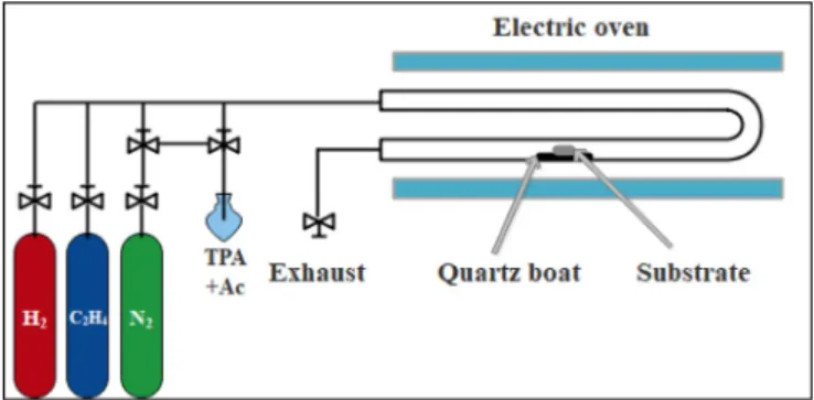
The synthesis times for aluminum, titanium and silicon substrates were 15, 30 and 20 min, respectively. According to the literature these parameters proved to be the most suitable for the synthesis of CNT forests, with the view to incorporate nitrogen into the CNTs [3,4,16]. At the end of the synthesis, the quartz reactor was removed from the furnace, all gasflows were closed except for nitrogen, the quartz reactor was let to cool down andfinally, the sample was taken out for sub- sequent analysis. The schematic image of the equipment used for the CCVD is presented inFig. 1.
2.4. Sample characterization
To obtain information about both the structure and height of carbon nanotube forests, the samples were investigated using a Hitachi S-4700 Type II FESEM (5–15 keV) scanning electron microscope (SEM). The incorporation of nitrogen into the CNT structure was studied by energy- dispersive X-ray spectroscopy (EDX) measurements with a Röntec XFlash 3001 detector (20 keV). The quality of the carbon nanotubes were examined using transmission electron microscopy (TEM, FEI Tecnai G2 20 X-TWIN, 200 keV). Raman spectroscopy measurements were also carried out using a Thermo Scientific DXR Raman microscope (excitation wavelength: 532 nm) to collect information on the graphi- tization degree of the samples.
Table 1
The gas feed during the syntheses.
Gas feed (cm3/min)
Substrate Nitrogen/Carrier Hydrogen Ethylene TPA-Ac
Aluminum 40 50 70 45
Titanium 40 80 70 45
Silicon 50 100 110 45
Fig. 1.Schematic image of the CCVD system.
3. Results and discussion
In order to gather information about the nitrogen incorporation into CNT forest structures we attempted to apply different metallic sub- strates and various catalyst building techniques. However, in some cases, not only nitrogen incorporation but also the formation of aligned carbon nanotube arrangement was not successful either. For instance, the application of PLD method facilitated the CNT forest formation in the cases of silicon and titanium substrates, then again it was inefficient using aluminum substrate [12,16]. Applying the dip-coating method a general conclusion could be drawn, that the overall quality of the forest (e.g.height, graphitization) was poorer using either of the given sub- strates (except for silicon), probably due to the significant irregularity (roughness) of the catalyst layer. The above-mentionedfindings made the proper comparison more difficult; however, after taking into con- sideration these shortcomings, still valuable observation could be made referring to the mechanism of nitrogen incorporation.
3.1. The effect of various substrates on nitrogen incorporation
In the literature, N incorporation into carbon nanotubes is generally investigated on CNT forests made on silicon substrate; however, other substrates can also be suitable to grow N-doped CNT forests. Moreover, the properties of the substrates can have a significant effect both on the structure and the height of carbon nanotube forests, thus they might influence nitrogen incorporation as well. For this reason, CNT forests were grown on the surface of three different substrates (aluminum, ti- tanium, and silicon) in this study and the aim was to obtain information about the structure of carbon nanotube forests, and about the in- corporation of nitrogen into their structures as well. It is worth men- tioning that different reaction conditions were set individually for each substrate in accordance with the purposes of the present study.
Fig. 2 shows SEM images of the as-prepared samples while the heights of CNT forests and atomic ratios obtained from EDX measure- ments are summarized inTable 2.
From the SEM data it can be seen that the carbon nanotube forests significantly differ in height which, besides the nature of substrates, might be influenced by the reaction temperature as well. The applica- tion of Si substrate–which is generally used to reach millimeter-high CNT forests in the literature[35]–provided the highest CNT forest, probably due to the synergistic effect of the high temperature used during the synthesis (which favors CNT growth) and the advantageous properties of the substrate. However, by analyzing the EDX results which provide information about nitrogen incorporation, it was found that the highest N/C ratio belongs to the Al substrate, which may be due to the lower reaction temperature. It is well known that higher tem- perature favors higher graphitization, thus the elimination of heteroa- toms from the carbonaceous structure, therefore, the probability of N incorporation is also higher at lower reaction temperatures.
Based on the above-mentioned theory it is a quite surprising ob- servation that the lowest N/C ratio (0.17) was detected on titanium substrate, which emphasizes the importance of the role of substrates both in the growth of CNT forest and the incorporation of nitrogen.
Using silicon substrate, the N/C ratio was 0.20, which is a lower value than that of aluminum but higher than the ratio obtained in the case of titanium. It has to be mentioned that based on the literature higher temperatures facilitate the incorporation of nitrogen into carbon na- notubes[36]; however, this effect might occur due to the higher ability of the applied N-containing source to be activated. The special behavior of titanium substrate may be explained by the ability of the metallic titanium to absorb[37]the nitrogen present in the system, which re- sults in less nitrogen being incorporated into the carbon nanotube structures.
Substrates were fabricated for blank synthesis, which differed from the normal synthesis since no carbon source was introduced into the system. These syntheses provided information on the morphology of the catalyst particles and the substrate coverage. Representative SEM images for each substrate can be seen inFig. 3.
Based on the SEM images, it can be observed that the catalyst particles were evenly distributed in the case of titanium and silicon substrates, which is due to the fact that the PLD method can form a more uniform catalyst layer on the substrate surface and the catalyst particles have nearly the same diameter (Table 2). However, in the case of the aluminum substrate, the catalyst particles were fused and less separated, due to the fact that the dip-coating method was made it possible to form a thicker catalyst layer on the substrate surface and the mean diameter of the catalyst particles was also significantly larger (Table 2).
The effects of nitrogen incorporation on the graphitic nature of CNTs were investigated. As it has already been observed in the litera- ture, higher nitrogen incorporation into the structure decreases the graphitization of carbon nanotubes [20], therefore, Raman spectro- scopy measurements were carried out (shown inFig. 4) and theID/IG
ratio values characteristic of the graphitic structure are listed in Table 2. Since nitrogen incorporation might modify the structure of CNT walls andID/IGratio values, consequently, defect sites in carbon nanotubes can be correlated with higher nitrogen uptake. However, reaction temperature also affects the graphitization degree. Comparing these two effects, the following conclusions can be drawn.
Based on theID/IGratios calculated from the Raman spectra, the CNT forests produced on the Al substrate showed the highest number of defect sites, which can be in correlation with the highest nitrogen up- take observed in this sample. In turn, the carbon product grown on titanium substrate also contained significant amount of defect sites, nevertheless, in this case it was not coupled with high nitrogen
Fig. 2.SEM images of CNT forests grown on various substrates.
Table 2
ID/IGvalues from Raman measurements, N/C atomic percentages obtained from EDX, the heights of CNT forests (h) for various substrates, diameter of catalyst particle from SEM and diameter of CNT from TEM.
Substrate N/C (at.%)
h (µm) ID/IG Diameter of catalyst particle (nm)
Diameter of CNT (nm)
Al 0.24 11.1 ± 1.1 1.27 86.1 ± 37.2 8 ± 2.7
Ti 0.17 15.7 ± 7.8 1.13 27.8 ± 5 15 ± 4.6
Si 0.20 77.4 ± 4.6 0.98 26.2 ± 6.5 13 ± 2.3
incorporation, which may be due to the nitrogen absorption capacity of metallic titanium mentioned above. CNT forests made on silicon sub- strate exhibited the most graphitic carbon nanotubes due to the high synthesis temperature, but the nitrogen incorporation is not negligible in this case either.
As the next step, the samples were measured by TEM to obtain in- formation about the structure of the CNTs and the incorporation of nitrogen into the CNTs, which is shown inFig. 5.
In the TEM images can be observed that the diameters of the CNTs produced on titanium and silicon substrates were almost the same and their structure were not different either, which may confirm the ni- trogen incorporation observed by the EDX measurements. However, the average diameter of the CNT was somewhat smaller for the aluminum substrate, its structure was very similar to those grown on the other two substrates, which may attest nitrogen incorporation, which was also observed in EDX measurements.
Since from the as-investigated samples the highest nitrogen uptake was observed when Al substrate was applied in the case of dip-coating, thus a catalyst layer was built on the surface of titanium substrate by the dip-coating method as well and then the nitrogen uptake was in- vestigated in the same way. Similar experiments with silicon substrate did not provide any aligned carbon nanotube structure.
3.2. The effect of dip-coated catalyst layers on nitrogen incorporation
Conclusions from the previous section, i.e. considerable N in- corporation over aluminum (with dip-coating), and poor nitrogen doping on titanium substrate (with PLD) highlighted the possible ad- vantages of the former technique. Therefore, in the following experi- ments, dip-coating was used to form the catalyst layer on a titanium substrate, and the changes in nitrogen incorporation was investigated.
As it was already mentioned in the experimental section, when the dip- coating method was applied the substrate was heat treated prior to the layer deposition, which might result in a thicker titania layer on the surface of the substrate. These experiments opened up the possibility to reveal if the formation of an insulating layer between the metallic ti- tanium and the released nitrogen can facilitate nitrogen incorporation (instead of absorption into metallic titanium), thus increasing the N/C ratio of CNT forests. Relevant results of SEM, EDX and Raman spec- troscopy measurements are summarized inFig. 6andTable 3.
Based on the results it can be concluded that it is possible to achieve CNT forest structure on dip-coated titanium substrate; however, SEM images revealed that the structure of the CNT forests formed on PLD layer is less dense, and they were slightly taller. From the EDX mea- surements it can be seen that the amount of incorporated nitrogen in these cases was 0%, which may be due to the fact that the titanium absorbed all the nitrogen introduced into the system and the formation of insulating layer mentioned above was not able to hinder this process.
According to the Raman spectroscopy results the sample contained a small number of defect sites, nevertheless, the ID/IGratio was found to be even lower than in the case of PLD catalyst layer.
Therefore, further syntheses were carried out in order to promote the incorporation of nitrogen. The original synthesis method was Fig. 3.SEM images of CNT forests pre-synthesized with different substrates.
Fig. 4.Raman spectra of CNT forests grown on different substrates.
Fig. 5.TEM images of carbon nanotubes synthesized with different substrates.
slightly modified, namely, after the reduction step only the gas stream of the carbon source was opened to facilitate the formation of a uniform carbon layer on the surface of titanium substrate, thus preventing the absorption of nitrogen in the substrate. 10 min later the gas feed of the TPA-Ac mixture was also started, later the gas feed of the TPA-Ac mixture was also started, with the aim of incorporating nitrogen into the just arranging carbon nanotubes forest structure. SEM, EDX and Raman spectroscopy measurements were performed again on the as- prepared CNT forests (Table 3,Fig. 7).
From the SEM image it can be concluded, that it is possible to obtain CNT forest structure in this case as well; however, compared to the previous sample, the height of CNT forest was doubled, and the CNT forest did not develop as a uniform layer on the substrate surface, but rather as a group of somewhat separated islands. Despite our efforts, no nitrogen incorporation into the CNT forest was observed in this case either, which may be due to the fact that the catalyst layer was thicker and more uneven after the deposition process via dip-coating. The rough catalyst layer can explain the irregularity of CNT forest on one hand, and also the unchanged availability of titanium substrate for nitrogen, on the other. Similarly as before, a blank synthesis was pre- pared to obtain information about the morphology and CNT diameter in the case of the dip-coated samples, which was then followed up by TEM measurements (Fig. 8).
In the SEM image, it can be observed that the location of the catalyst particles on the surface of the substrate was almost the same as on the surface of the aluminum substrate (Table 3), due to the fact that the dip- coating method forms a thicker catalyst layer on the substrate surface, their diameter was also larger than the catalyst particles produced by the PLD method. In the TEM image, the diameter of the CNTs was found to be 23.36 ± 9.46 nm, and its structure was not outstanding, which may be due to the dip-coting method, as no nitrogen incorporation into the CNTs was observed based on EDX measurements.
Moreover, Raman spectroscopy measurement demonstrated higher graphitization which suggests the lower probability of nitrogen in- corporation during the modified synthesis. Summarizing the effect of
“carbon pretreatment”, it was found that in contrast with prior ex- pectation, the modified synthesis does not facilitate the incorporation of nitrogen into the carbon nanotube structure. Presumably, the presence of an insulating Al2O3layer applied during the PLD method cannot be replaced by applying certain conditions during the dip-coating method.
This layer can prevent nitrogen absorption and thus promote the
formation of N-doped CNT forests.
4. Summary
We studied the nitrogen uptake ability of CNT forests grown on different substrates under optimized conditions for obtaining sufficient yield. We can conclude that all the three applied substrates were cap- able to facilitate nitrogen incorporation; however, the value of N/C ratio and the appropriate layer building method varied significantly.
For aluminum substrate only the dip-coating technique, and for silicon substrate only PLD was suitable to grow aligned CNT structure. The application of titanium substrate resulted in the formation of the de- sired forest structure with both methods, although there was a con- siderable difference in nitrogen uptake. Further experiments confirmed that this phenomenon can be attributed to the nitrogen absorption ability of the titanium substrate in the absence of the insulating layer.
Although different synthesis conditions were applied for different substrates, we can observe general trends. It is well-known that reaction temperature can significantly influence the degree of graphitization, therefore higher temperature is beneficial to fabricate CNT structures free of defect sites, thus free of heteroatoms. This would indicate that lower temperatures are favorable for nitrogen incorporation, but we should thrive for a tradeoff, since too low temperature would not pro- mote the activation of N-containing organic source. As our mainfinding we confirmed that the fabrication of N doped CNT forests on conducting substrates is possible, which may open the way for further applications Fig. 6.SEM image of CNT forest grown on a dip-coated titanium surface.
Table 3
ID/IGvalues from Raman measurements, N/C atomic percentages obtained from EDX, the heights of CNT forests in the case of dip-coated titanium substrates (*with 10 min carbon pretreatment) diameter of catalyst particle from SEM and diameter of CNT from TEM.
Substrate N/C (at.%) h (µm) ID/IG Diameter of catalyst particle (nm) Diameter of CNT (nm)
Ti 0.00 18.5 ± 1.2 1.05 117.2 ± 47.3 23.4 ± 9.5
Ti_dip_10 min* 0.00 31.3 ± 5 0.91 117.2 ± 47.3 –
Fig. 7.SEM image of CNT forest grown on a dip-coated titanium surface with 10 min carbon pretreatment.
Fig. 8.SEM images of CNT forests pre-synthesized and TEM images of carbon nanotubes synthesized with the dip-coated sample.
to exploit their advantageous properties.
CRediT authorship contribution statement
Anna Szabó:Investigation, Writing - original draft, Visualization.
Tamás Gyulavári: Methodology, Writing - review & editing.Zsejke- Réka Tóth: Methodology. Zsuzsanna Pápa: Methodology. Judit Budai: Data curation, Writing - review & editing. Klara Hernadi:
Funding acquisition, Supervision.
Declaration of Competing Interest
It is hereby declared that we have no known competingfinancial interests or personal relationships that could appeared to influence the work reported in this paper.
Acknowledgements
This work was supported by the GINOP-2.3.2-15-2016-00013 pro- ject and the ÚNKP-19-3-SZTE-264 New National Excellence Program of the Ministry for Innovation and Technology.
References
[1] W.Z. Li, S.S. Xie, L.X. Qian, B.H. Chang, B.S. Zou, W.Y. Zhou, R.A. Zhao, G. Wang, Large-scale synthesis of aligned carbon nanotubes, Science (80-.). 274 (1996) 1701–1703,https://doi.org/10.1126/science.274.5293.1701.
[2] Z. Pápa, E. Kecsenovity, D. Fejes, J. Budai, Z. Toth, K. Hernadi, Height and diameter dependence of carbon nanotube forests on the porosity and thickness of catalytic layers, Appl. Surf. Sci. 428 (2018) 885–894,https://doi.org/10.1016/j.apsusc.
2017.09.206.
[3] L. Nánai, A. Szabó, T. Gyulavári, J. Budai, K. Hernadi, Manual spray coating : a cheap and effective method to build catalyst layers for carbon nanotube forest growth, Thin Solid Films 689 (2019) 137491, ,https://doi.org/10.1016/j.tsf.2019.
137491.
[4] A. Szabó, E. Kecsenovity, Z. Pápa, T. Gyulavári, K. Németh, E. Horvath, K. Hernadi, Influence of synthesis parameters on CCVD growth of vertically aligned carbon nanotubes over aluminum substrate, Sci. Rep 7 (2017) 1–11,https://doi.org/10.
1038/s41598-017-10055-0.
[5] S. Noda, K. Hasegawa, H. Sugime, K. Kakehi, Z. Zhang, S. Maruyama, Y. Yamaguchi, Millimeter-thick single-walled carbon nanotube forests: hidden role of catalyst support, Jpn. J. Appl. Phys. Part 2 Lett. 46 (2007) L399–L401,https://doi.org/10.
1143/JJAP.46.L399.
[6] N. Halonen, K. Kordás, G. Tóth, T. Mustonen, J. Mäklin, J. Vähäkangas, P.M. Ajayan, R. Vajtai, Controlled CCVD synthesis of robust multiwalled carbon nanotubefilms, J. Phys. Chem. C 112 (2008) 6723–6728,https://doi.org/10.1021/
jp7110617.
[7] A. Kaneko, K. Yamada, R. Kumahara, H. Kato, Y. Homma, Comparative study of catalytic activity of iron and cobalt for growing carbon nanotubes on alumina and silicon oxide, J. Phys. Chem. C 116 (2012) 26060–26065,https://doi.org/10.1021/
jp309232w.
[8] P. Kim, C.J. Lee, The reduction temperature effect of Fe–Co/MgO catalyst on characteristics of multi-walled carbon nanotubes, Catal. Commun. 8 (2018) 361, https://doi.org/10.3390/catal8090361.
[9] N.F.W. Thissen, M.A. Verheijen, R.G. Houben, C. Van Der Marel, W.M.M. Kessels, A.A. Bol, Synthesis of single-walled carbon nanotubes from atomic-layer- deposited Co3O4and Co3O4/Fe2O3catalystfilms, Carbon N. Y. 121 (2017) 389–398,https://
doi.org/10.1016/j.carbon.2017.06.001.
[10] C. Mattevi, C.T. Wirth, S. Hofmann, R. Blume, M. Cantoro, C. Ducati, C. Cepek, A. Knop-Gericke, S. Milne, C. Castellarin-Cudia, S. Dolafi, A. Goldoni, R. Schlögl, J. Robertson, In-situ X-ray photoelectron spectroscopy study of catalyst- support interactions and growth of carbon nanotube forests, J. Phys. Chem. C 112 (2008) 12207–12213,https://doi.org/10.1021/jp802474g.
[11] H. Watanabe, J. Ishii, K. Ota, Novel growth method of carbon nanotubes using catalyst-support layer developed by alumina grit blasting, Nanotechnology 27 (2016) 335605, ,https://doi.org/10.1088/0957-4484/27/33/335605.
[12] A. Szabó, P. Andricević, Z. Pápa, T. Gyulavári, K. Németh, E. Horvath, L. Forró, K. Hernadi, Growth of CNT forests on titanium based layers, detailed study of catalysts, Front. Chem. 6 (2018) 593,https://doi.org/10.3389/fchem.2018.00593.
[13] A. Szabó, L.P. Bakos, D. Karajz, T. Gyulavári, Z. Tóth, Decoration of vertically aligned carbon nanotubes with semiconductor nanoparticles using atomic layer deposition, Materials 12 (2019) 1095,https://doi.org/10.3390/ma12071095.
[14] E. Roumeli, M. Diamantopoulou, M. Serra-garcia, P. Johanns, G. Parcianello, C.
Daraio, Characterization of vertically aligned carbon nanotube forests grown on
stainless steel surfaces, 9 (2019) 18–25. doi:10.3390/nano9030444.
[15] G. Atthipalli, Y. Tang, A. Star, J.L. Gray, Electrochemical characterization of carbon nanotube forests grown on copper foil using transition metal catalysts, Thin Solid Films 520 (2011) 1651–1655,https://doi.org/10.1016/j.tsf.2011.08.105.
[16] D. Fejes, Z. Pápa, E. Kecsenovity, B. Réti, Z. Toth, K. Hernadi, Super growth of vertically aligned carbon nanotubes on pulsed laser deposited catalytic thinfilms, Appl. Phys. A Mater. Sci. Process. 118 (2015) 855–861,https://doi.org/10.1007/
s00339-014-8965-3.
[17] E.N. Nxumalo, N.J. Coville, Nitrogen doped carbon nanotubes from organometallic compounds: a review, Materials 3 (2010) 2141–2171,https://doi.org/10.3390/
ma3032141.
[18] J. Liu, S. Webster, D.L. Carroll, N. Carolina, Temperature andflow rate of NH3
effects on nitrogen content and doping environments of carbon nanotubes grown by injection CVD method, J. Phys. Chem. B 109 (2005) 15769–15774.
[19] T. Thurakitseree, C. Kramberger, P. Zhao, S. Aikawa, S. Harish, S. Chiashi, E. Einarsson, S Maruyama, Diameter-controlled and nitrogen-doped vertically aligned single-walled carbon nanotubes, Carbon N. Y. 50 (2012) 2635–2640, https://doi.org/10.1016/j.carbon.2012.02.023.
[20] H.C. Choi, J. Park, B. Kim, Distribution and structure of N atoms in multiwalled carbon nanotubes using variable-energy X-ray photoelectron spectroscopy, J. Phys.
Chem. B 109 (2005) 4333–4340,https://doi.org/10.1021/jp0453109.
[21] S. Boncel, S.W. Pattinson, V. Geiser, M.S.P. Shaffer, K.K.K. Koziol, En route to controlled catalytic CVD synthesis of densely packed and vertically aligned ni- trogen-doped carbon nanotube arrays, Beilstein J. Nanotechnol. 5 (2014) 219–233, https://doi.org/10.3762/bjnano.5.24.
[22] Y. Lai, H. Lian, K. Lee, Diamond & related materialsfield emission of vertically aligned carbon nanotubes with various content of nitrogen, Diam. Relat. Mater. 18 (2009) 544–547,https://doi.org/10.1016/j.diamond.2008.10.011.
[23] A. Mashayekhi, S. Mahmoud, M. Hassanpour, A. Naser, Plasma-assisted nitrogen doping of VACNTs for efficiently enhancing the supercapacitor performance, J.
Nanoparticle Res. 18 (2016) 154,https://doi.org/10.1007/s11051-016-3470-6.
[24] S. Point, T. Minea, B. Bouchet-fabre, A. Granier, G. Turban, XPS and NEXAFS characterisation of plasma deposited vertically aligned N-doped MWCNT, Diam.
Relat. Mater. 14 (2005) 891–895,https://doi.org/10.1016/j.diamond.2004.10.
011.
[25] G.P. Szekeres, K. Nemeth, A. Kinka, M. Magyar, B. Reti, E. Varga, Z. Szegletes, A. Erdohelyi, L. Nagy, K. Hernadi, Segmental nitrogen doping and carboxyl func- tionalization of multi-walled carbon nanotubes, Phys. Status Solidi Basic Res. 252 (2015) 2472–2478,https://doi.org/10.1002/pssb.201552163.
[26] R.M. Silva, A.J.S. Fernandes, M.C. Ferro, N. Pinna, R.F. Silva, Applied surface sci- ence vertically aligned N-doped CNTs growth using Taguchi experimental design, Appl. Surf. Sci. 344 (2015) 57–64,https://doi.org/10.1016/j.apsusc.2015.03.073.
[27] Y. Li, F. Hou, Z. Yang, J. Feng, X. Zhong, J. Li, The growth of N-doped carbon nanotube arrays on sintered Al2O3substrates, Mater. Sci. Eng. B Solid-State Mater.
Adv. Technol. 158 (2009) 69–74,https://doi.org/10.1016/j.mseb.2009.01.009.
[28] P. Ghosh, T. Soga, K. Ghosh, R.A. Afre, T. Jimbo, Y. Ando, Vertically aligned N- doped carbon nanotubes by spray pyrolysis of turpentine oil and pyridine derivative with dissolved ferrocene, J. Non Cryst. Solids 354 (2008) 4101–4106,https://doi.
org/10.1016/j.jnoncrysol.2008.05.053.
[29] P. Oil, S.A. Bakar, S. Muhamad, P. Sarah, M. Saad, R. Nor, Y.M. Siran, S.A. Rejab, Effect of temperature on the growth of vertically aligned carbon nanotubes effect of temperature on the growth of vertically aligned carbon nanotubes from palm oil, Defect Diffus. Forum Vols 312–315 (2011) 900–905,https://doi.org/10.4028/
www.scientific.net/DDF.312-315.900.
[30] Y.G. Lin, Y.K. Hsu, C.T. Wu, S.Y. Chen, K.H. Chen, L.C. Chen, Diamond & related materials effects of nitrogen-doping on the microstructure, bonding and electro- chemical activity of carbon nanotubes, Diam. Relat. Mater. 18 (2009) 433–437, https://doi.org/10.1016/j.diamond.2008.09.009.
[31] K. Lee, Y. Lin, Y. Chen, Y. Huang, Influence of the nitrogen content on the elec- trochemical capacitor characteristics of vertically aligned carbon nanotubes, Phys.
E Low-Dimensional Syst. Nanostruct. 42 (2010) 2799–2803,https://doi.org/10.
1016/j.physe.2010.01.011.
[32] T. Hiraoka, T. Yamada, K. Hata, D.N. Futaba, H. Kurachi, S. Uemura, M. Yumura, S. Iijima, Synthesis of single- and double-walled carbon nanotube forests on con- ducting metal foils, J. Am. Chem. Soc. 128 (2006) 13338–13339,https://doi.org/
10.1021/ja0643772.
[33] K. Gong, F. Du, Z. Xia, M. Durstock, L. Dai, Nitrogen-doped carbon nanotube arrays with high electrocatalytic activity for oxygen reduction, Science (80-.). 323 (2009) 760–764,https://doi.org/10.1126/science.1168049.
[34] N.G. Tsierkezos, S.H. Othman, U. Ritter, Nitrogen-doped multi-walled carbon na- notubes for paracetamol sensing, Ionics 19 (2013) 1897–1905,https://doi.org/10.
1007/s11581-013-0930-1.
[35] K. Hata, D.N. Futaba, K. Mizuno, T. Namai, M. Yumura, S. Iijima, Water-assisted highly efficient synthesis of impurity-free single-walled carbon nanotubes, Science (80-.). 306 (2004) 1362–1364,https://doi.org/10.1126/science.1104962.
[36] Y.T. Lee, N.S. Kim, S.Y. Bae, J. Park, Growth of vertically aligned nitrogen-doped carbon nanotubes : control of the nitrogen content over the temperature range 900 - 1100°C, J. Phys. Chem. B. 107 (2003) 12958–12963,https://doi.org/10.1021/
jp0274536.
[37] V.L. Stout, M.D. Gibbons, Gettering of gas by titanium, J. Appl. Phys. 26 (1955) 1488,https://doi.org/10.1063/1.1721936.