Available online 11 December 2021
0025-5408/© 2021 The Author(s). Published by Elsevier Ltd. This is an open access article under the CC BY-NC-ND license
(http://creativecommons.org/licenses/by-nc-nd/4.0/).
incorporation into carbon nanotube forests
Anna Szab ´ o
a, Gergo Peter Szekeres
a,1, Tam ´ as Gyulav ´ ari
a, Zsejke R ´ eka T oth ´
a,b,
Zsuzsanna P ´ apa
c, Akos Szamosv ´ ¨ olgyi
a, Andr ´ as S api ´
a, Zolt an K ´ ´ onya
a, Klara Hernadi
a,d,*aDepartment of Applied and Environmental Chemistry, University of Szeged, H-6720 Szeged, Rerrich B´ela t´er 1, Hungary
bNanostructured Materials and Bio-Nano-Interfaces Center, Institute for Interdisciplinary Research on Bio-Nano-Sciences, Babeș-Bolyai University, Treboniu Laurian 42, RO-400271, Cluj-Napoca, Romania
cDepartment of Optics and Quantum Electronics, University of Szeged, Szeged H-6720, D´om t´er 9, Hungary
dInstitute of Physical Metallurgy, Metal Forming and Nanotechnology, University of Miskolc, H-3515 Miskolc-Egyetemv´aros, Hungary
A R T I C L E I N F O Keywords:
Carbon nanotubes
Catalytic chemical vapor deposition Nitrogen doping
Pulsed laser deposition Dip-coating Tripropylamine
A B S T R A C T
Nitrogen doping carbon nanotubes can enhance their beneficial physical and chemical properties, rendering them more desirable for various applications, e.g., in electronics. In this study, we used catalytic chemical vapor deposition to synthesize carbon na-no-tube forests on different substrates. The samples were prepared in the presence of compounds containing nitrogen (ammonia, acetonitrile, tripropylamine, and their mixture with acetone) that were introduced into the reactor by bubbling or injection. Of the two different nitrogen intro- duction methods, the direct injection of a liquid nitrogen precursor promoted the synthesis of bamboo-structured carbon nanotube forests more efficiently. It was found in the injection experiments that the amount of precursor affected the extent of nitrogen incorporation. The presence of various nitrogen species in CNTs was also iden- tified, and the manner in which temperature and the presence of hydrogen both influence nitrogen incorporation into the carbon na-no-tubes was observed.
1. Introduction
Nowadays, carbon nanotubes (CNTs) play an important role due to their prominent chemical and physical properties. The vertical align- ment of CNTs into so-called “CNT forests” results in a three-dimensional structure and enhanced properties [1]. This way their conductivity can be improved, which is beneficial in e.g., microelectromechanical ap- pliances [2]. This structure was first produced by a team of researchers in Beijing in 1996, who used catalytic chemical vapor deposition (CCVD) for the synthesis [3]. To synthesize CNT forests a catalyst is required that is prepared most often as a thin film either by spray-coating [4], dip-coating [5], spin-coating [6], or pulsed laser deposition (PLD) [7]. Popular catalyst precursors include different salts of iron [8], cobalt [9], and nickel [10]. Before thin film construction, it is important to choose the optimal (often conductive) substrate based on the experimental needs, such as titanium [11], aluminum [12], stainless steel [13], and copper [14], but silicon has also been used [15] due to its
abundance and resistance to temperature in a wide range.
In order to enhance the electrochemical properties of CNTs, they are often doped with nitrogen atoms, thus exhibiting an n-type behavior [16]. Nitrogen doping (N-doping) adds extra electrons to the carbon lattice increasing the electron density in the conduction and valence bands, which plays an important role in their application. Several methods are available to synthesize N-doped CNT forests, such as in- jection [17,18], dosing [19], pyrolysis [20], nitrogen plasma generation [21], plasma-assisted N-doping [22], electron cyclotron resonance [23], or bubbling [24]. These often result in a modified CNT structure, such as bamboo-like nanotubes. Different nitrogen compounds can be used to dope CNTs, e.g., acetonitrile [19], ethylenediamine [25], 4‑tert-bu- tylpyridine [26], palm oil [27], tripropylamine [24,28,29] and, most commonly, ammonia [30–32]. Based on current knowledge, when CNT forests are formed on a conductive substrate, the conductive properties can be increased; however, there are only a few examples in the litera- ture of this, such as N-doped CNT forests produced on stainless steel [33,
* Corresponding author.
E-mail address: hernadi@chem.u-szeged.hu (K. Hernadi).
1 Current address for G.P.S.: Institut für Chemie und Biochemie, Freie Universit¨at Berlin, Arnimallee 22, 14195 Berlin, Germany; Department of Molecular Physics, Fritz-Haber-Institut der Max-Planck-Gesellschaft, Faradayweg 4–6, 14195 Berlin, Germany
https://doi.org/10.1016/j.materresbull.2021.111676
Received 16 September 2021; Received in revised form 30 November 2021; Accepted 5 December 2021
34]. During synthesis, many parameters affect the incorporation of ni- trogen into the carbon lattice of CNT forests. For example, hydrogen has been shown to have an inhibitory effect on nitrogen incorporation [17].
N-doped CNTs are used in various applications, such as fuel cells [35], sensors [36], hydrogen storage [37], Li-ion batteries [38], and CO2
adsorption [39], as well as in organic pollutant removal [40].
This work aims to observe the effect of different nitrogen compounds that were used as nitrogen precursors for the synthesis of N-doped CNT forests. Moreover, the influence of other experimental parameters on the structure of CNT forests and the incorporation of nitrogen into CNTs were also investigated. Since N-doped CNT forests have mostly been produced on silicon substrates, our goal was to synthesize vertically aligned N-doped CNTs on metallic substrates, too. For this purpose, ti- tanium and aluminum substrates were used to diversify the conductive properties of the products for a wide range of possible applications. The parameters used in the syntheses were based on previous results [5,11], so that only the N-doping parameters could be analyzed in the research.
2. Experimental 2.1. Materials
Three different substrates were used for the syntheses: aluminum (99.99%, VWR), silicon (<100>, P-type, Sigma), and titanium (99%, VWR). Cobalt (cobalt(II) nitrate hexahydrate, 99% (Sigma-Aldrich)), cobalt(II) oxide (99.99%, Sigma-Aldrich), iron (iron(III) nitrate non- ahydrate, 99.9%, Sigma-Aldrich), iron(III) oxide (99.998%, Sigma- Aldrich), ethanol (99.8%, VWR), and aluminum oxide (≥98.5%, WRS Materials Company) were used to prepare the catalyst. Nitrogen doping experiments were performed using three different nitrogen precursors:
tripropylamine (TPA; ≥98%, Sigma-Aldrich), ammonia (NH3; 25% so- lution, VWR), and acetonitrile (ACN; a.r., J.T. Baker). Acetone (Ac; a.r., Molar Chemicals Kft.) was used together with the nitrogen compounds to increase volatility. During the syntheses, nitrogen (99.995%, Messer) was used as the carrier gas, hydrogen (99.5%, Messer) as the reducing agent, and ethylene (>99.9%, Messer) as the carbon source.
2.2. Catalyst preparation
Two different methods were used to prepare the catalyst layers: dip- coating, which is a simple approach, and PLD, which yields a more
homogeneous catalytic surface. The substrates were prepared identi- cally in both catalyst layer deposition approaches: the three different substrates (aluminum, silicon, and titanium) were cut to size (2 ×2 cm), then rinsed with ethanol, acetone, and Milli-Q water to remove surface contaminants.
For dip-coating, the catalyst solution was prepared by dissolving Fe (NO3)3 ×9H2O and Co(NO3)2 ×6H2O in ethanol at a concentration of 0.11 M, respectively. The catalyst ink was prepared by mixing these solutions at an Fe:Co ratio of 2:3. The catalyst solutions were always prepared fresh to avoid decomposition and undesirable product forma- tion. The clean substrates were heat-treated at 400 ◦C for 1 h in a static oven to form a surface layer of native oxide, which was followed by catalyst deposition on the surface. Then, the substrates with the catalysts were heat-treated once more at 400 ◦C for 1 h to stabilize the catalyst layer on the substrate.
In the first step of PLD, catalyst pastilles were prepared using Fe2O3
and CoO with an Fe:Co ratio of 1:1. 1 g of catalyst precursor was weighed, then compressed into pellets with a diameter of 1 cm. This was followed by heat-treatment at 400 ◦C for 1 h to stabilize the catalysts.
The Al2O3 pellet for the support layer formation was also prepared by the process described above. The support and the catalyst layers were then built by placing the substrate in the vacuum chamber. After that, the support and catalyst layers were deposited from the pastilles by using an LLG TWINAMP KrF excimer laser (λ =248 nm, pulse length: 18 ns, repetition rate: 10 Hz) operated at an average fluence of 20 J/cm2. The catalyst with the support layer present on the substrate was analyzed by ellipsometry (Fig. S1). Ellipsometric analysis showed that both the support and the catalyst layer had a thickness of 5 nm. The change in the Fe:Co ratio in the catalysts prepared by two different techniques is rationalized by our previous works [5,11].
2.3. CCVD synthesis
The same steps were taken in the case of the different substrates, only the reaction time, temperature, and gas flow were varied based on the ideal parameters determined in our earlier works [5,11,15]. In the first step, a 0.4 ×0.4 cm piece of the catalyst-coated substrate was placed in an open quartz boat, then put in a tubular quartz reactor. The reactor was then purged in a preheated tube furnace under nitrogen. During this process, the temperature was set to 640 ◦C for the aluminum substrate (due to its low melting point), 700 ◦C for the titanium substrate, and Fig. 1. Schematic image of the dip-coating, PLD method [41] and the CCVD system.
700–820 ◦C for the silicon substrate. Hydrogen was then introduced to provide a reductive atmosphere in the system. During the syntheses studying the effect of hydrogen, this step was varied, and during the injection experiments, it was completely omitted. After 5 min, ethylene and the nitrogen precursor (with or without acetone) were introduced.
The introduction of the nitrogen precursors was done using two different methods. When it was carried out by bubbling (further referred to as
“bubbling experiments”), the nitrogen gas flowed through the liquid nitrogen precursor, bringing the vapor and small droplets of the pre- cursor into the reactor. When it was carried out by injection, the nitro- gen precursor was introduced directly into the system as a continuous flow of liquid (also referred to as “injection experiments”). The synthesis time was 15 min for the aluminum substrate, 30 min for the titanium substrate, and 20 min for the silicon substrate. At the end of the syn- thesis, the quartz reactor was removed from the tube furnace, all the gas flows were shut off except for nitrogen. After the reactor cooled down, the samples were collected and characterized. The flow rate during bubbling was 45 cm3/min for each substrate, and the flow of the directly injected nitrogen precursor in the injection experiments was set to 3, 6, or 9 mL within 30 min (this experiment was only performed for the titanium-based catalyst). A schematic illustration of the catalyst prepa- ration and the equipment used for the CCVD synthesis is presented in Fig. 1.
2.4. Characterization of samples
The samples were characterized with a Hitachi S-4700 Type II FESEM (5–15 keV) scanning electron microscope (SEM) to obtain in- formation on the structure and height of CNT forests. During these measurements, the samples were characterized also by energy- dispersive X-ray spectroscopy (EDX) with a R¨ontec XFlash Detector 3001 to obtain information on the presence of nitrogen in the CNTs.
Transmission electron microscopy (TEM) experiments were performed with a FEI Tecnai G2 20 X-TWIN microscope (200 keV) to gain infor- mation on the structure of CNTs complementary to the SEM measure- ments. The Raman spectra of the samples were recorded with a Thermo Scientific DXR Raman microscope (λexcitation = 532 nm, spectrum acquisition time = 2 min/spectrum) to collect information on the graphitization of the samples. The spectra of each sample were recorded at three different positions, which were then averaged prior to
calculating the ID/IG band intensity ratios. X-ray photoelectron spec- troscopy (XPS) analysis was performed with an XR-50 dual anode X-ray source and a Phoibos 150 energy analyzer to obtain information about the C–N bonds in the N-doped CNTs. The instrument was operated at 150 W (14 kV) to obtain Al Kα radiation as the X-ray source.
3. Results and discussion
3.1. Effect of different nitrogen compounds on CNT forest growth First, the syntheses were performed on aluminum substrates with three different nitrogen precursors that were introduced by bubbling.
The goal of these experiments was to investigate the effects of using different nitrogen precursors and the incorporation of nitrogen atoms on the characteristic structure of CNT forests. The aluminum-supported catalyst was chosen for these experiments to provide an alternative, potentially more cost-effective option for the synthesis of CNT forests on a conductive substrate. This has already been shown to be suitable for the production of CNT forests based on previous results [5]. The three nitrogen precursor compounds were NH3, ACN, and TPA, as these are abundantly used in the literature for nitrogen doping due to their high volatility [24,32,42]. The samples were subjected to SEM and EDX measurements and the results are shown in Fig. 2 and Table 1. The green frame around a micrograph indicates that the sample possesses desirable characteristics for further testing, while the red frame indicates the opposite.
Based on the SEM images it was ascertained that CNT forests did not form under the experimental conditions used, only CNTs with common structural features (Fig. 2). In the sample prepared with NH3, mostly catalyst particles could be found. The absence of CNT forest structure can be explained by the fact that NH3 is prone to poison Co-based cat- alysts [43]. Another explanation might be that the nitrogen resulting from the decomposition of NH3 was adsorbed on the surface of iron particles, preventing the surface diffusion of carbon [17] and thus the growth of CNTs. In both cases, the high N/C ratio shown in Table 1 is evident. In the samples prepared with ACN and TPA, CNTs could be observed on the substrate, but they were not aligned vertically. This may be due to the absence of a somewhat oxidative atmosphere, such as water vapor. Its beneficial effect on the formation of CNT forests has already been discussed in the literature, i.e., that it activates the catalyst and contributes to the alignment of CNTs into CNT forests [44].
3.2. Effect of acetone on the structure of CNT forests on aluminum substrate
The effect of acetone was studied in bubbling experiments to inves- tigate its possible assistance in the introduction of the nitrogen com- pounds into the system, and its possible oxidative effects on the CNT forest structures. As it is known from the literature acetone is an accompanying component in acetylene gas cylinders, and as an oxigen- Fig. 2. SEM images of carbon deposit synthesized in the presence of NH3 (left), ACN (middle), and TPA (right) on aluminum substrate.
Table 1
N/C atomic ratios determined based on the EDX results in the CNT forests using different nitrogen compounds.
N/C
NH3 2.05
ACN 0.26
TPA 0.14
containing carbon source it has been proved to promote the growth of CNTs [45]. In these experiments, the three nitrogen compounds were respectively mixed with 30% acetone and the nitrogen compound-acetone mixture flow rate was set to 45 cm3/min. The cata- lysts on aluminum substrate were used in these experiments to directly compare these results with those obtained without using acetone. For these syntheses, the reaction time was set to 15 min and the temperature to 640 ◦C. The samples were analyzed by SEM, EDX, and Raman spec- troscopy, and the results are shown in Fig. 3 and Table 2.
Based on the SEM images, it can be observed that the presence of TPA (together with acetone) promoted the formation of CNT forests. How- ever, for NH3 and ACN, CNT forests could not be observed. Compared to the bubbling experiments without acetone, more CNTs were synthesized in the presence of acetone due to its oxidative properties. These prop- erties are expected to contribute to the degradation of amorphous car- bon, thus regenerating the catalyst particles, which contributes to the growth of CNT forests [44]. Furthermore, due to its high volatility, acetone also facilitated the introduction of the nitrogen compounds used into the quartz reactor.
Based on the EDX results (Table 2), nitrogen was successfully incorporated. This is further supported by the results of Raman spec- troscopic measurements (Fig. S2), where the ID/IG ratio was 1.27, sug- gesting a relatively high number of defect sites, which has already been proposed in our previous work as a sign of nitrogen incorporation [24].
Due to the results obtained in the presence or absence of acetone, the
TPA-acetone mixture was used in further experiments.
3.3. Effect of acetone on the structure of CNT forests on titanium substrate
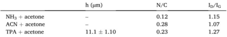
The focus of these experiments was to assess the effect of the sub- strate on the incorporation of nitrogen. Using titanium as a substrate also allowed us to apply higher synthesis temperatures that are more common in the literature, and whose effect on the formation of CNT forests has already been investigated in previous studies [46]. The pa- rameters used in these syntheses were the same as those described in the experimental section, except for the synthesis temperature that was set to 700 ◦C. SEM, EDX, and Raman spectroscopy measurements of the samples were performed and summarized in Fig. 4 and Table 3.
In the SEM images (Fig. 4), it can be observed that only CNTs were formed on the substrate when NH3 and ACN were used as nitrogen precursors. On one hand, this could be caused by the ability of NH3 to poison the catalyst as discussed above. On the other hand, this could be due to the high vapor pressure of ACN. As a result, it can easily over- saturate the system and potentially block certain properties of the catalyst that contribute to the vertical alignment of CNTs. At the same time, CNTs (with a height of 10.2 ±2.2 µm) grew in the presence of TPA- acetone, exhibiting structural traits characteristic of CNT forests. EDX measurements were carried out to investigate if nitrogen was incorpo- rated into the CNTs (Table 3). Surprisingly, no nitrogen incorporation Fig. 3. SEM images of CNTs synthesized in the presence of NH3 (left), ACN (middle), and TPA (right) mixed with 30% acetone on aluminum substrate.
Table 2
Height of the CNT forests (h), N/C atomic ratios determined based on EDX re- sults, and ID/IG band intensity ratios obtained from Raman spectra for CNT forests on aluminum substrate.
h (µm) N/C ID/IG
NH3 +acetone – 0.12 1.15
ACN +acetone – 0.28 1.07
TPA +acetone 11.1 ±1.10 0.23 1.27
Fig. 4. SEM images of CNTs synthesized in the presence of NH3 (left), ACN (middle), and TPA (right) mixed with 30% acetone on titanium substrate.
Table 3
Height of the CNT forests (h), N/C atomic ratios determined based on EDX re- sults, and ID/IG band intensity ratios obtained from Raman spectra for CNT forests on titanium substrate.
h (µm) N/C ID/IG
NH3 +acetone – 0.0 0.92
ACN +acetone – 0.0 0.9
TPA +acetone 10.2 ±2.2 0.0 1.1
was observed, which could be due to the titanium substrate, as the chemisorption of nitrogen atoms on it is a well-known undesirable process in materials science [47,48]. This may have occurred before nitrogen could incorporate into the CNT lattice. Based on the Raman spectroscopy measurements (Table 3, Fig. S2), the ID/IG ratio for TPA-acetone was 1.1, suggesting the presence of defect sites in the structure. This can originate from the incorporation of nitrogen in such a
small amount that is below the detection limit of EDX. When NH3 and ACN were used, the as-obtained CNTs could be described as graphitic;
however, in these cases, the structure typical of CNT forests was not formed. Based on these results, aluminum-supported catalyst layers are more suitable for the synthesis of nitrogen-doped CNT forests than dip-coated titanium-supported catalysts. Although, we have shown previously that such structures can be synthesized on titanium sub- strates as well by using PLD for the preparation [29].
3.4. Effect of temperature on the properties of CNT forest
The effects of temperature on the incorporation of nitrogen into the CNTs as well as on their growth were systematically studied using the TPA-acetone mixture. Higher temperatures have been shown to increase the graphitization of CNTs [49], while they may also facilitate the quick evaporation and decomposition of TPA, thus helping the incorporation of nitrogen atoms into the forest structures. In the experiments per- formed in a wide temperature range, that is, at 640–820 ◦C, catalysts on silicon wafers were used due to the durability of silicon at higher tem- peratures [50]. The synthesis parameters were identical to those described above, only the reaction time was changed to 20 min, which is the optimal reaction time on silicon substrates [7,15]. While the SEM and TEM images of the samples synthesized at 700–820 ◦C are shown in Fig. 5, the Raman spectroscopy and EDX results are summarized in Table 4.
It can be observed in the SEM images (Fig. 5) that the height of the CNT forests (Table 4) produced at 740 ◦C and 780 ◦C was almost the same. This is because 740–780 ◦C is the most ideal temperature range for their synthesis [15]. At 700 ◦C, which was the lowest temperature used, slightly lower CNT forests were obtained, which may be due to the sub-optimal temperature, resulting in slower growth on the substrate. At 820 ◦C, remarkably lower CNT forests were obtained (Fig. 5, rightmost column), possibly due to the oxidative effect of acetone present in the system. At this temperature it presumably began to decompose the CNT forests [51]. Based on the EDX and Raman results (Table 4, Fig. S2), the nitrogen content in the CNTs increased with increasing temperature, while the graphitic structure also increased. This is in agreement with previous observations, specifically that the graphiticity of the samples increases with increasing temperature up to a certain threshold, above which a thin amorphous layer is deposited [52,53]. The XPS results (Table 5, Fig. S3) suggest that as the temperature increased in the optimal temperature range, the incorporation of nitrogen into the CNTs increased as well, which is consistent with the EDX results. Comparing Fig. 5.SEM and TEM images of CNT forests synthesized at 700 ◦C, 740 ◦C, 780 ◦C, and 820 ◦C.
Table 4
Height of the synthesized CNT forests (h), N/C atomic ratios obtained from EDX experiments, diameter of the synthesized CNTs based on TEM micrographs, and ID/IG band ratios calculated from Raman spectra at different synthesis temperatures.
h (µm) N/C Diameter of CNT (nm) ID/IG
700 ◦C 49.30±1.68 0.02 13.75±2.02 1.27
740 ◦C 63.42±1.60 0.18 7.31±1.83 1.11
780 ◦C 64.22±1.40 0.20 8.59±2.53 0.94
820 ◦C 13.24±1.34 0.23 14.00±2.93 0.85
Table 5
Relative atomic composition of CNT forests from XPS experiments at different synthesis temperatures.
At%
sp2 C C–C C–N C–O C =O O–C =O π–π*
700 ◦C 93.99 – 0.53 – – 1.94 3.54
740 ◦C 86.66 2.45 0.61 2.53 0.8 2.78 4.16
780 ◦C 66.62 19.43 0.97 3.83 1.5 5.06 2.6
820 ◦C 72.08 11.97 1.86 6.47 1.75 3.42 2.46
Table 6
Relative atomic composition of CNT forests for various N species from XPS ex- periments at different synthesis temperatures.
At%
C =N–C
(Pyridinic) C-NH–C
(Pyrrolic) C=(NH+)–C (Graphitic) NOx
(Oxidized) Higher NOx + satellite
700 ◦C – 4.47 59.74 3.69 32.09
740 ◦C 6.22 12.55 36.9 15.53 28.8
780 ◦C 10.92 12.68 26.88 9.83 39.7
820 ◦C 5.19 6.04 88.77 – –
the results of these two methods, it can be observed that the numbers are rather different from each other, with the XPS generally under- estimating the numbers obtained with EDX. This originates from the fact that for such samples the sensitivity of XPS is lower than that of EDX.
Based on the literature, the graphitic structure becomes more prevalent with increasing temperature [54], which is consistent with our results.
Even though defect sites are often introduced via nitrogen incorpora- tion, the XPS results (Table 6) suggest that this process can also result in the formation of a graphitic structure. At 820 ◦C, the percentage of the graphitic structure among C–N bonds is the highest, thus nitrogen incorporation could indeed increase the overall graphitic structure of
the CNT forest. Furthermore, the graphitic structure also increases with the synthesis temperature, which can eventually compensate for the defects introduced by the nitrogen atoms [55]. In the TEM micrographs (Fig. 5, bottom row), possible defect sites can be observed in all the CNTs investigated. These defect sites include the separation of CNT walls, and the turns along the CNT main axis. Such structural changes have already been observed in our previous work as signs of nitrogen incorporation [24].
The experiments were also performed at 640 ◦C to compare the re- sults with those obtained for the aluminum-supported catalyst; however, the resulting CNTs were randomly aligned (Fig. S5). Since CNT forests were successfully produced on aluminum substrate at this temperature, these results prove that it is crucial what kind of substrate is chosen for the given reaction conditions. Moreover, it can be concluded that aluminum is a potentially suitable substrate, due to its physical prop- erties, price, and relatively low temperature requirements. It also pro- vides an optimal low-cost alternative for the synthesis of vertically aligned N-doped CNT forests on a conducting substrate.
3.5. Effect of hydrogen on the properties of CNT forests
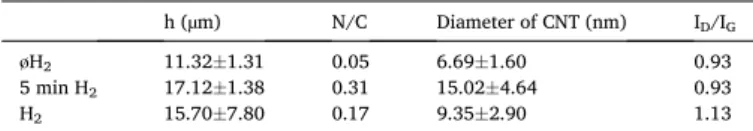
We studied the influence of hydrogen flow on the structure of the CNT forest as well as on the incorporation of nitrogen atoms. The Fig. 6. SEM and TEM images of CNTs synthesized in the absence of hydrogen (left column), under hydrogen flow for 5 min (middle column), and under continuous hydrogen flow (right column).
Table 7
Heights (h), N/C atomic ratios, diameters of the synthesized CNTs, and ID/IG
band intensity ratios obtained from Raman experiments. Standard errors of forest heights and CNT diameters were calculated from approximately 30 and 100 measurements, respectively, in different hydrogen presence.
h (µm) N/C Diameter of CNT (nm) ID/IG
øH2 11.32±1.31 0.05 6.69±1.60 0.93
5 min H2 17.12±1.38 0.31 15.02±4.64 0.93
H2 15.70±7.80 0.17 9.35±2.90 1.13
Fig. 7. SEM images of CNT forests synthesized by the introduction of varying amounts of TPA via injection.
rationale behind these experiments was that hydrogen presumably in- hibits the incorporation of nitrogen into CNTs [56]. However, hydrogen can reduce the catalyst [57], which plays an important role in the pro- duction of CNT forests. The titanium-supported catalysts were prepared with PLD as its ability to strongly promote the formation of nitrogen-doped CNT forests has been shown before [11]. The SEM and TEM images of the samples are shown in Fig. 6, while Raman spectro- scopic and EDX results are summarized in Table 7. Three cases were investigated as follows: in the first case, hydrogen was not present in the system during the synthesis (Fig. 6, left column); in the second case, it was present for the first 5 min until it reduced the catalyst particles (Fig. 6, middle column); in the third case, it was present in the reactor throughout the synthesis (Fig. 6, right column). TPA with 30% acetone was used as the nitrogen source, their flow rate was 45 cm3/min, and the
reaction time was 30 min.
In the SEM images, it can be observed that CNT forests were formed on the titanium substrate even without hydrogen. Although, their quality was different from those grown in the presence of hydrogen. This could be because ethylene reduces the catalyst particles at the beginning of the reaction. However, since hydrogen is not present in the system, only catalyst particles of a lower oxidation state can be formed. This may affect the height of the CNT forests as well as the incorporation of ni- trogen. Based on these results, it can be concluded that the reduction step indeed plays an important role in the syntheses. The amount of nitrogen built into the CNT structures was measured by EDX and the results are summarized in Table 7. It was concluded that using 5 min hydrogen flow during the synthesis resulted in the highest nitrogen content in the CNTs. The average height of the CNT forests was also the highest in this sample. These may be because hydrogen is important to reduce the catalyst at the beginning of the synthesis, but after the initial 5 min, it did not counteract the oxidative atmosphere necessary for the growth of CNTs. As a result, the catalyst particles may have been in a more reduced state. The samples were also subjected to Raman spec- troscopic studies (Fig. S2), and the results are shown in Table 7. Based on the measurements, a high ratio of defect sites was present in the CNT forests. This could be due to the incorporation of nitrogen, and that in our previous study the CNT forests prepared on a titanium substrate have also exhibited a large number of defect sites [11]. In the TEM micrographs, it can be observed that when hydrogen was introduced, new structural features and defects appeared. This may be due to the increased incorporation of nitrogen into the CNTs or the saturation of carbon atoms with hydrogen before they could arrange into a graphitic lattice. The largest CNT diameters were observed in the sample that was prepared under hydrogen for 5 min, which could also result from the higher amount of incorporated nitrogen [32]. The CNTs were composed of 7–8 walls in general. Based on these results, it can be concluded that even without hydrogen it is possible to synthesize CNT forests. Intro- ducing hydrogen into the reactor for the first 5 min provides a reductive environment that later promotes the incorporation of nitrogen into CNTs.
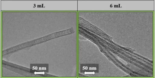
Fig. 8.TEM images of individual CNTs synthesized by the introduction of varying amounts of TPA via injection.
Table 8
Height of CNT forests (h), N/C atomic ratios obtained from EDX, diameters of CNTs based on TEM micrographs, and ID/IG band intensity ratios calculated from the Raman spectra of samples synthesized by the injection of varying amounts of TPA.
Injected TPA amount h (µm) N/C Diameter of CNT (nm) ID/IG
3 mL 1.38±0.11 3.60 26.59±2.11 0.83
6 mL 1.57±0.28 2.59 11.40±3.03 0.82
9 mL – 4.10 – 0.86
Table 9
Relative atomic composition of CNT forests from XPS experiments of samples synthesized by the injection of varying amounts of TPA.
At%
sp2 C C–C C–N C–O C =O O–C =O π-π*
3 mL 68.88 16.19 1.76 5.58 1.69 3.28 2.63
6 mL 76.27 14.1 2.68 1.86 0.51 1.7 2.88
9 mL 75.86 14.17 2.51 3.23 0.95 0.86 2.42
Table 10
Relative atomic composition of CNT forests for various N species from XPS experiments of samples synthesized by the injection of varying amounts of TPA.
At%
C =N–C (Pyridinic) C–NH–C(Pyrrolic) –– NOx (Oxidized) Higher NOx +satellite
3 mL 21.65 4.26 70.8 3.29 –
6 mL 17.06 18.55 44.19 20.19 –
9 mL 20.08 15.14 47.15 17.62 –
reactor, based on our observations in previous experiments [46]. The corresponding SEM and TEM images of the samples are shown in Figs. 7–8, and the Raman spectroscopic and EDX results are summarized in Table 8.
Based on the SEM images (Fig. 7), injecting 3 mL and 6 mL TPA resulted in the formation of CNT forest structures on the substrates. The height of the CNT forests was very low compared to that of the other CNT forests shown Fig. 6. Based on the literature this can be quite beneficial. It has become increasingly important to produce CNT forests that are as short as possible [60–62] to make them easier to use, for example in solar collectors [63]. When 9 mL of TPA feed was used, no structure resembling a CNT forest could be observed. This may be because if too much TPA feed is used, it overloads the catalyst when it comes to the formation of an arranged nanotube array. This overload results in the precursor no longer decomposing catalytically. Thus, thermal homogeneous decomposition is inevitable due to the applied temperature, resulting in the formation of a thick amorphous carbon layer on the surface of the substrate. Due to the introduction of high volumes of TPA (relative to the volumes introduced by bubbling), it is possible that the trapped TPA molecules between the CNTs account for a significant portion of the N/C atomic ratios calculated from the EDX results (Table 8). Therefore, XPS experiments were performed to learn about the relative number of nitrogen atoms incorporated into the CNT lattice. Based on the XPS results (Table 9, Fig. S4), it can be concluded that injecting 6 mL of TPA resulted in the highest N/C atomic ratio.
During nitrogen incorporation, most of the nitrogen was incorporated as a graphitic structure (Table 10). Combining this result with the lowest ID/IG ratio, this sample may possess more desirable conductive proper- ties overall. When observing the individual CNTs in the TEM images (Fig. 8), bamboo-like structures could be identified, which is a known structural change caused by the incorporation of nitrogen into the CNT walls [24,64]. The EDX results indicate higher N/C ratios than those calculated after carrying out any of the experiments in which TPA was introduced via bubbling. The Raman results (Fig. S2) suggest an increased graphitic structure in all the samples obtained from these experiments, which is probably the result of the high temperature applied during the syntheses.
4. Conclusions
It was concluded that CNT forest structure can be successfully syn- thesized using a mixture of TPA-acetone on aluminum and titanium substrates. Nitrogen was incorporated only for the aluminum substrate but not for the titanium substrate. CNT forest structure did not form when pure nitrogen compounds were used. The graphitization in the samples was enhanced at high temperature; however, high temperature was also favorable for nitrogen incorporation into the lattice of CNTs.
Therefore, it was ascertained that the properties of the substrate affect the incorporation of nitrogen. The effects of hydrogen on the growth of CNTs and incorporation of nitrogen were also studied. Hydrogen was only required in the reduction phase, but not during the growth phase, in order to the hydrogen not to exert an inhibitory effect. This resulted in higher CNT forests and increased nitrogen incorporation into the CNTs.
It was found that the injection method was more efficient for the
Anna Szab´o: Conceptualization, Visualization, Investigation, Writing – original draft, Formal analysis. Gergo Peter Szekeres:
Conceptualization, Visualization, Data curation. Tam´as Gyulav´ari:
Investigation, Software. Zsejke R´eka T´oth: Investigation, Data cura- tion. Zsuzsanna P´apa: Investigation, Visualization. Akos Sza-´ mosv¨olgyi: Formal analysis, Writing – review & editing. Andr´as S´api:
Supervision, Writing – review & editing. Zolt´an K´onya: Supervision, Visualization. Klara Hernadi: Writing – review & editing, Supervision, Resources.
Declaration of Competing Interest
The authors declare that they have no known competing financial interests or personal relationships that could have appeared to influence the work reported in this paper.
Acknowledgements
The Author appreciate the financial support of NKFIH 2019–2.1.11- TET-2020´ –00134.
References
[1] L. Qiu, X. Zhang, Z. Guo, Q. Li, Interfacial heat transport in nano-carbon assemblies, Carbon N. Y. 178 (2021) 391–412, https://doi.org/10.1016/j.
carbon.2021.02.105.
[2] M. Dahmardeh, M. Vahdani Moghaddam, M. Hian Tee, A. Nojeh, K. Takahata, The effects of three-dimensional shaping of vertically aligned carbon-nanotube contacts for micro-electro-mechanical switches, Appl. Phys. Lett. 103 (2013), 231606, https://doi.org/10.1063/1.4844695.
[3] W.Z. Li, S.S. Xie, L.X. Qian, B.H. Chang, B.S. Zou, W.Y. Zhou, R.A. Zhao, G. Wang, Large-Scale Synthesis of Aligned Carbon Nanotubes, Science (80-.). 274 (1996) 1701–1703. doi:10.1126/science.274.5293.1701.
[4] L. Nanai, A. Szab´o, T. Gyulav´ari, J. Budai, K. Hern´adi, Manual spray coating: a cheap and effective method to build catalyst layers for carbon nanotube forest growth, Thin Solid Films 689 (2019) 137491–137499, https://doi.org/10.1016/j.
tsf.2019.137491.
[5] A. Szab´o, E. Kecsenovity, Z. P´apa, T. Gyulav´ari, K. N´emeth, E. Horvath, K. Hernadi, Influence of synthesis parameters on CCVD growth of vertically aligned carbon nanotubes over aluminum substrate, Sci. Rep. 7 (2017) 1–11, https://doi.org/
10.1038/s41598-017-10055-0.
[6] P. Mauron, C. Emmenegger, A. Zuttel, C. Nutzenadel, L. Schlapbach, S ynthesis of oriented nanotube films by chemical vapor deposition, Carbon Nanotub. 40 (2002) 1339–1344, https://doi.org/10.1016/S0008-6223(01)00295-0.
[7] Z. P´apa, E. Kecsenovity, D. Fejes, J. Budai, Z. Toth, K. Hernadi, Height and diameter dependence of carbon nanotube forests on the porosity and thickness of catalytic layers, Appl. Surf. Sci. 428 (2018) 885–894, https://doi.org/10.1016/j.
apsusc.2017.09.206.
[8] S. Noda, K. Hasegawa, H. Sugime, K. Kakehi, Z. Zhang, S. Maruyama, Y. Yamaguchi, Millimeter-thick single-walled carbon nanotube forests: hidden role of catalyst support, Japanese J. Appl. Physics, Part 2 Lett. 46 (2007) L399–L401, https://doi.org/10.1143/JJAP.46.L399.
[9] Y. Murakami, Y. Miyauchi, S. Chiashi, S. Maruyama, Study of the productivity of MWCNT over Fe and Fe–Co catalysts supported on SiO2, Al2O3 and MgO, Appl.
Phys. Lett. 23 (2011) 1–4, https://doi.org/10.1016/j.snb.2012.12.112.
[10] E. Roumeli, M. Diamantopoulou, M. Serra-garcia, P. Johanns, G. Parcianello, C.
Daraio, Characterization of vertically aligned carbon nanotube forests grown on stainless steel surfaces, 9 (2019) 18–25. doi:10.3390/nano9030444.
[11] A. Szab´o, P. Andricevi´c, Z. P´apa, T. Gyulav´ari, K. N´emeth, E. Horvath, L. Forr´o, K. Hernadi, Growth of CNT forests on titanium based layers, detailed study of catalysts, Front. Chem. 6 (2018) 1–9, https://doi.org/10.3389/fchem.2018.00593.
compounds: a review, Materials (Basel) 3 (2010) 2141–2171, https://doi.org/
10.3390/ma3032141.
[17] J. Liu, S. Webster, D.L. Carroll, N. Carolina, Temperature and flow rate of NH3 effects on nitrogen content and doping environments of carbon nanotubes grown by injection CVD method, J. Phys. Chem. B. 109 (2005) 15769–15774.
[18] S. Boncel, S.W. Pattinson, V. Geiser, M.S.P. Shaffer, K.K.K. Koziol, En route to controlled catalytic CVD synthesis of densely packed and vertically aligned nitrogen-doped carbon nanotube arrays, Beilstein J. Nanotechnol. 5 (2014) 219–233, https://doi.org/10.3762/bjnano.5.24.
[19] T. Thurakitseree, C. Kramberger, P. Zhao, S. Aikawa, S. Harish, S. Chiashi, E. Einarsson, S. Maruyama, Diameter-controlled and nitrogen-doped vertically aligned single-walled carbon nanotubes, Carbon N. Y. 50 (2012) 2635–2640, https://doi.org/10.1016/j.carbon.2012.02.023.
[20] H.C. Choi, J. Park, B. Kim, Distribution and Structure of N atoms in multiwalled carbon nanotubes using variable-energy X-ray photoelectron spectroscopy, J. Phys.
Chem. B. 109 (2005) 4333–4340, https://doi.org/10.1021/jp0453109.
[21] Y. Lai, H. Lian, K. Lee, Diamond &, Related Materials Field emission of vertically aligned carbon nanotubes with various content of nitrogen, Diam. Relat. Mater. 18 (2009) 544–547, https://doi.org/10.1016/j.diamond.2008.10.011.
[22] A. Mashayekhi, S. Mahmoud, M. Hassanpour, A. Naser, Plasma-assisted nitrogen doping of VACNTs for efficiently enhancing the supercapacitor performance, J. Nanoparticle Res. 18 (2016) 154, https://doi.org/10.1007/s11051-016-3470-6.
[23] S. Point, T. Minea, B. Bouchet-fabre, A. Granier, G. Turban, XPS and NEXAFS characterisation of plasma deposited vertically aligned N-doped MWCNT, Diam.
Relat. Mater. 14 (2005) 891–895, https://doi.org/10.1016/j.
diamond.2004.10.011.
[24] G.P. Szekeres, K. Nemeth, A. Kinka, M. Magyar, B. Reti, E. Varga, Z. Szegletes, A. Erdohelyi, L. Nagy, K. Hernadi, Segmental nitrogen doping and carboxyl functionalization of multi-walled carbon nanotubes, Phys. Status Solidi Basic Res.
252 (2015) 2472–2478, https://doi.org/10.1002/pssb.201552163.
[25] Y. Li, F. Hou, Z. Yang, J. Feng, X. Zhong, J. Li, The growth of N-doped carbon nanotube arrays on sintered Al2O3 substrates, Mater. Sci. Eng. B Solid-State Mater.
Adv. Technol. 158 (2009) 69–74, https://doi.org/10.1016/j.mseb.2009.01.009.
[26] P. Ghosh, T. Soga, K. Ghosh, R.A. Afre, T. Jimbo, Y. Ando, Vertically aligned N- doped carbon nanotubes by spray pyrolysis of turpentine oil and pyridine derivative with dissolved ferrocene, J. Non. Cryst. Solids. 354 (2008) 4101–4106, https://doi.org/10.1016/j.jnoncrysol.2008.05.053.
[27] P. Oil, S.A. Bakar, S. Muhamad, P. Sarah, M. Saad, R. Nor, Y.M. Siran, S.A. Rejab, Effect of temperature on the growth of vertically aligned carbon nanotubes effect of temperature on the growth of vertically aligned carbon nanotubes from palm oil, defect diffus, Forum Vols. (2011) 900–905, https://doi.org/10.4028/www.
scientific.net/DDF.312-315.900, 312–315.
[28] K. N´emeth, G.P. Szekeres, D. Fejes, B. Reti, J.W. Seo, L. Forr´o, K. Hernadi, Controlling the structure of carbon deposit by nitrogen doping catalytic chemical vapor deposition synthesis, J. Nanosci. Nanotechnol. 21 (2021) 2413–2418, https://doi.org/10.1166/jnn.2021.18965.
[29] A. Szab´o, T. Gyulav´ari, Z.R. T´oth, Z. P´apa, J. Budai, K. Hernadi, The effect of various substrates and catalyst layer deposition on the incorporation of nitrogen into carbon nanotube forest structures, Thin Solid Films 709 (2020), 138194, https://doi.org/10.1016/j.tsf.2020.138194.
[30] R.M. Silva, A.J.S. Fernandes, M.C. Ferro, N. Pinna, R.F. Silva, Applied surface science vertically aligned N-doped CNTs growth using Taguchi experimental design, Appl. Surf. Sci. 344 (2015) 57–64, https://doi.org/10.1016/j.
apsusc.2015.03.073.
[31] T.M. Minea, B. Bouchet-Fabre, S. Lazar, S. Point, H.W. Zandbergen, Angular and local spectroscopic analysis to probe the vertical alignment of N-doped well- separated carbon nanotubes, J. Phys. Chem. B. 110 (2006) 15659–15662, https://
doi.org/10.1021/jp0637072.
[32] S.K. Srivastava, V.D. Vankar, D.V.S. Rao, V. Kumar, Enhanced field emission characteristics of nitrogen-doped carbon nanotube films grown by microwave plasma enhanced chemical vapor deposition process, 515 (2006) 1851–1856. doi:
10.1016/j.tsf.2006.07.016.
[33] K. Lee, Y. Lin, Y. Chen, Y. Huang, Influence of the nitrogen content on the electrochemical capacitor characteristics of vertically aligned carbon nanotubes, Phys. E Low-Dimensional Syst, Nanostructures 42 (2010) 2799–2803, https://doi.
org/10.1016/j.physe.2010.01.011.
[34] P. Subramanian, A. Cohen, E. Teblum, G.D. Nessim, E. Bormasheko, A. Schechter, Electrocatalytic activity of nitrogen plasma treated vertically aligned carbon nanotube carpets towards oxygen reduction reaction, Electrochem. Commun. 49 (2014) 42–46, https://doi.org/10.1016/j.elecom.2014.10.005.
[40] Y. Yao, H. Chen, C. Lian, F. Wei, D. Zhang, G. Wu, B. Chen, S. Wang, Co Fe, Ni nanocrystals encapsulated in nitrogen-doped carbon nanotubes as Fenton-like catalysts for organic pollutant removal, J. Hazard. Mater. 314 (2016) 129–139, https://doi.org/10.1016/j.jhazmat.2016.03.089.
[41] H. Soonmin, S.A. Vanalakar, A. Galal, V.N. Singh, A review of nanostructured thin films for gas sensing and corrosion protection, Mediterr. J. Chem. 7 (2018) 433–451, https://doi.org/10.13171/MJC7618111916HS.
[42] A.G. Kurenya, L.G. Bulusheva, I.P. Asanov, O.V. Sedelnikova, A.V. Okotrub, Field emission properties of aligned CNx nanotube arrays synthesized by pyrolysis of a ferrocene/acetonitrile aerosol at different temperatures, Phys. Status Solidi Basic Res. 252 (2015) 2524–2529, https://doi.org/10.1002/pssb.201552265.
[43] A.C. Kizilkaya, J.W. Niemantsverdriet, C.J. Weststrate, Effect of ammonia on cobalt Fischer-Tropsch synthesis catalysts: a surface science approach, Catal. Sci. Technol.
9 (2019) 702–710, https://doi.org/10.1039/c8cy01723a.
[44] K. Hata, D.N. Futaba, K. Mizuno, T. Namai, M. Yumura, S. Iijima, Water-assisted highly efficient synthesis of impurity-free single-walled carbon nanotubes, Science (80-.) 306 (2004) 1362–1364, https://doi.org/10.1126/science.1104962.
[45] K. Hernadi, A. Fonseca, P. Piedigrosso, M. Delvaux, J.B. Nagy, D. Bernaerts, J. Riga, Carbon nanotubes production over Co/silica catalysts, Catal. Letters. 48 (1997) 229, https://doi.org/10.1023/A:1019035306217.
[46] A. Szab´o, L. N´anai, Z.R. T´oth, K. Hernadi, Simplification of the CCVD method used in the growth of carbon nanotube forests on titanium substrate, Solid State Sci 117 (2021), 106648, https://doi.org/10.1016/j.solidstatesciences.2021.106648.
[47] L. Soriano, M. Abbate, J.C. Fuggle, C. Jim´enez, J.M. Sanz, L. Gal´an, C. Mythen, H.
A. Padmore, The interaction of nitrogen with titanium studied by soft X-ray absorption spectroscopy: adsorption versus implantation, Surf. Sci. 281 (1993) 120–126, https://doi.org/10.1016/0039-6028(93)90861-D.
[48] J. Xu, C.D. Lane, J. Ou, S.L. Cockcroft, D.M. Maijer, A. Akhtar, Y. Marciano, Diffusion of nitrogen in solid titanium at elevated temperature and the influence on the microstructure, J. Mater. Res. Technol. 12 (2021) 125–137, https://doi.org/
10.1016/j.jmrt.2021.02.073.
[49] J.Q. Huang, M.Q. Zhao, Q. Zhang, J.Q. Nie, L. De Yao, D.S. Su, F. Wei, Efficient synthesis of aligned nitrogen-doped carbon nanotubes in a fluidized-bed reactor, Catal. Today. 186 (2012) 83–92, https://doi.org/10.1016/j.cattod.2011.10.021.
[50] E.R. Meshot, L. Plata, S. Tawfick, Y. Zhang, E.A. Verploegen, A.J. Hart, Engineering vertically aligned carbon catalyst thermal treatment ofprecursor and nanotube growth by decoupled, ACS Nano 3 (2009) 2477–2486.
[51] V. Jourdain, C. Bichara, Current understanding of the growth of carbon nanotubes in catalytic chemical vapour deposition, Carbon N.Y. 58 (2013) 2–39, https://doi.
org/10.1016/j.carbon.2013.02.046.
[52] Q.N. Pham, L.A.S. Larkin, C.C. Lisboa, C.B. Saltonstall, L. Qiu, J.D. Schuler, T.
J. Rupert, P.M. Norris, Effect of growth temperature on the synthesis of carbon nanotube arrays and amorphous carbon for thermal applications, Phys. Status Solidi Appl. Mater. Sci. 214 (2017) 1–7, https://doi.org/10.1002/pssa.201600852.
[53] L. Qiu, K. Scheider, S.A. Radwan, L.A.S. Larkin, C.B. Saltonstall, Y. Feng, X. Zhang, P.M. Norris, Thermal transport barrier in carbon nanotube array nano-thermal interface materials, Carbon N. Y. 120 (2017) 128–136, https://doi.org/10.1016/j.
carbon.2017.05.037.
[54] Y.T. Lee, J. Park, Y.S. Choi, H. Ryu, H.J. Lee, Temperature-dependent growth of vertically aligned carbon nanotubes in the range 800-1100◦C, J. Phys. Chem. B.
106 (2002) 7614–7618, https://doi.org/10.1021/jp020488l.
[55] X. Qi, H. Xu, X.Q. Wang, W.G. Ma, C. Qiu, M. An, G. Zhang, F. Wang, X. Zhang, A. Bermak, Effective surface emissivity and heat dissipation among integrated bamboo-like super-black vertical carbon nanotube array electrodes in silicon via holes, Carbon N. Y. 158 (2020) 846–856, https://doi.org/10.1016/j.
carbon.2019.11.068.
[56] A. Hachimi, B. Merzougui, A. Hakeem, T. Laoui, G.M. Swain, Q. Chang, M. Shao, M.A. Atieh, Synthesis of Nitrogen-doped carbon nanotubes using injection-vertical chemical vapor deposition: effects of synthesis parameters on the nitrogen content, J. Nanomater. (2015) 14–22, https://doi.org/10.1155/2015/453725, 2015.
[57] Y. Ma, A.B. Dichiara, D. He, L. Zimmer, J. Bai, Control of product nature and morphology by adjusting the hydrogen content in a continuous chemical vapor deposition process for carbon nanotube synthesis, Carbon N. Y. 107 (2016) 171–179, https://doi.org/10.1016/j.carbon.2016.05.060.
[58] J. Liu, S. Webster, D.L. Carroll, J. Liu, S. Webster, D.L. Carroll, Highly aligned coiled nitrogen-doped carbon nanotubes synthesized by injection-assisted chemical vapor deposition Highly aligned coiled nitrogen-doped carbon nanotubes synthesized by injection-assisted chemical vapor deposition, 213119 (2006). doi:
10.1063/1.2202191.