Pseudo-ductility of Unidirectional Thin Ply Hybrid Composites in Longitudinal
Compression
PUTU SUWARTA, GERGELY CZÉL, MOHAMAD FOTOUHI, JAKUB RYCERZ and MCHAEL R. WISNOM
ABSTRACT
The compression response of unidirectional thin-ply carbon (C) standard thickness S-glass (SG) hybrid composites is presented. Gradual failure up to high strain has been demonstrated for [SG1/(C1/SG1)17] and [SG1/(C2/SG1)17] hybrid configurations. The favourable pseudo-ductile behaviour is due to progressive fragmentation and dispersed delamination of the thin ply carbon/epoxy layers. For the [SG1/(C3/SG1)17] configuration, sudden failure occurs at a lower strain, but still higher than the compression failure strain of the carbon fibres calculated from the manufacturer’s data sheet. The energy release rate concept can be used to qualitatively explain the behaviour of the different thickness hybrid laminates under compression.
INTRODUCTION
High-performance composites with ductile or pseudo-ductile behaviour are of great interest for safety-critical applications. It has been reported that by combining unidirectional (UD) thin carbon plies with standard thickness glass plies, progressive fragmentation of the carbon followed by stable delamination can be obtained, yielding a pseudo-ductile response in tension [1]. Czél et al. [2] have reported a benign change of slope in the load-compressive strain curve of an asymmetric unidirectional hybrid composite made of a thin M55 carbon/epoxy and thick glass/epoxy layers loaded in four-point bending which was due to the progressive fragmentation of carbon layer on the compression side.
In this paper, direct longitudinal compression testing with the ICSTM (Imperial College of Science, Technology and Medicine) method [3] is conducted for unidirectional hybrid specimens composed of thin M55 carbon/epoxy and standard thickness S-glass/913 epoxy plies.
____________
P. Suwarta1, G. Czél 2,1, M. Fotouhi3, J. Rycerz1, M.R. Wisnom,1
1Bristol Composites Institute (ACCIS), University of Bristol, BS8 1TR, UK
2Department of Polymer Engineering, Budapest University of Technology and Economics, Muegyetem rkp. 3, Budapest, H-1111 Hungary
3Department of Design and Mathematics, University of the West of England, Bristol BS16 1QY, UK
MATERIALS
The materials considered for the design and used for the experiments were standard thickness S-glass/epoxy supplied by Hexcel and thin M55 carbon/epoxy supplied by North Thin Ply Technology. The epoxy resin in the prepregs were the aerospace grade 913 (Hexcel) and ThinPreg 120 EPHTg-402 (North TPT). The curing temperature for both resins in the designed hybrid laminates was 125 oC and they were found to be compatible. During test procedures, good integrity of the hybrid laminates was confirmed, and no phase separation was observed on the cross-sectional micrographs. Basic properties of the applied fibres and prepreg systems can be found in Table I and II where the subscript t and c refer to tension and compression respectively. The fibre properties in Table 1 are based on the manufacturer’s data and were determined from impregnated strands except for the S-glass where single fibre tests were performed.
TABLE I. FIBRE PROPERTIES OF THE APPLIED UD PREPREGS [2].
Fibre type Manufacturer E
(GPa)
ߩߩߩ ߩ (g/cm3)
ε ε ε εt (%)
σ σσ σt (GPa)
Torayaca M55JB Toray 540 1.91 0.8 4.02
FliteStrand S ZT S-glass Owens Corning 88 2.45 5.5 4.8-5.1
TABLE II. CURED PLY PROPERTIES OF THE APPLIED UD PREPREGS [2].
Prepreg type Fibre mass per unit area (g/m2)
t (ૄૄૄૄm)
VV
VVffff
(%) Ei (GPa)
ε εε εt (%)
ε ε ε εc (%)
M55 carbon/epoxy 30 30.5 52 280a 0.6b 0.26b
S-glass/epoxy 190 155 51 45.7 3.98 [4] 2.33b
acalculated for the given volume fraction.
bbased on manufacturer’s data for 60% carbon fibre volume fraction.
LAY-UP SEQUENCES AND MANUFACTURING METHOD
The unidirectional (UD) hybrid laminates made of standard thickness glass and thin carbon prepregs were arranged in the following sequence: [SG1/(Cn/SG1)17], where SG stands for S-glass plies and C for M55 carbon plies, values of n were 1, 2, and 3. Laminates were cured in an autoclave at the recommended cure temperature and pressure cycle for Hexcel 913 resin (60 min @ 125oC and 0.7 MPa), as this instruction is identical for the thin carbon prepreg cure cycle as well. A flat aluminium tool plate and silicon plates were used during the bagging and curing process.
Fabrication of the specimens was done using a diamond cutting wheel. End tabs of a 1.8 mm thick glass/epoxy woven plate supplied by Heathcotes Co. Ltd.were bonded to the specimens using an Araldite 2011 type two component epoxy adhesive supplied by Huntsman. A volume fraction ratio of 100:50 for A:B respectively was used for the mixed components and the bonded part was cured for 120 min @ 80 oC inside a fan convection oven. To ensure good alignment and flat surfaces, the tabs and ends of the specimen were then ground flat by a grinding machine.
TEST PROCEDURE
Mechanical testing of the glass/carbon hybrid specimens was conducted under longitudinal compression loading and displacement control using a cross-head speed of 1 mm/min on a computer controlled Instron 600DX type 600 kN rated universal hydraulic test machine. Load and strain readings were logged on a computer. The specimens were end-loaded in the Imperial College test rig shown in Figure 1. By using this test rig, the specimen is supported laterally over the whole length of the tabs.
Specimens were clamped lightly in position, and then end-loaded between flat hardened plates. The high precision die set used in the rig minimises frictional effects and ensures combined axial and shear load introduction from the end and the sides respectively. Nominal dimensions were overall length = 96 mm, gauge length = 12 mm, width = 10 mm and thickness (t) of 3.31 mm, 3.83 mm and 4.35 mm for the 17, 34 and 51 carbon ply specimens respectively. A schematic of the specimen geometry is shown in Figure 2. To measure the longitudinal surface strains, strain gauges of type C2A-06-062LW-120 with 4.45 x 2.03 mm overall length and width respectively were attached to both side of the specimens in the centre of the gauge length. An Imetrum video gauge system was also used to measure the longitudinal strain of the specimen’s gauge length at different points through the thickness by tracking the speckle pattern applied on the side surface using spray paint as shown in Figure 3. The thickness of the delaminated part shown in the recorded image was measured by using the ImageJ software. A scaling factor (mm/pixel) allows to calculate the thickness in mm. At least six specimens were tested of each type.
Figure 1. Imperial College compression test rig [3].
Figure 2. Schematic of the specimen geometry.
Figure 3. Strain measurement at three locations using video gauge system.
RESULTS AND DISCUSSION
The specimen types were classified according to the number of carbon plies incorporated in the hybrid laminates. Figure 4 shows the typical compressive stress- strain graphs for each hybrid configuration obtained from the tests, based on the average stress calculated using the nominal specimen dimensions. The compression strain is the average strain of the three strain measurements using the video gauge system shown in Figure 3. By incorporating more carbon plies into the hybrid laminate, the initial stiffness increased, as expected, which can be seen from different initial elastic slope of each stress-strain curve in Figure 4, where the [SG1/(C3/SG1)17] laminate has the highest initial stiffness.
Figure 4. Typical stress-strain curve for S-glass/M55 hybrid configurations.
During compression loading of the [SG1/(C1/SG1)17] and [SG1/(C2/SG1)17] configurations, a change of slope in the stress-strain curve appears at -0.49% which is believed to be due to fragmentation of the carbon plies under compression [2]. An earlier study to investigate the damage mechanisms behind the reduction in stiffness contribution from the carbon/epoxy layers in an asymmetric S-glass/M55 hybrid under four point bending [2] revealed multiple translaminar shear fractures running at an angle of around 45o through the carbon layers and local opening delamination at the intersections between inclined cracks and the glass/carbon layer interfaces. The low transverse stiffness and low through thickness interlaminar strength promoted this delamination [5]. It is also believed that this same damage mechanisms operated in direct compression for S-glass/M55 hybrid. It is clearly seen in Figure 4 that after - 0.49% strain, the stress continues to rise further. The -0.49% strain where the carbon plies fragmented is taken as the “knee-point strain” on the stress-strain curve and is determined from the intersection point of two lines fitted to the elastic (green line) and reduced slope regions (red line) as shown in Figure 5 for the hybrids with 17 and 34
carbon layers. The thickest laminate with 51 carbon layers, experienced sudden failure at -0.50% strain with the typical damage modes: fibre failure and delamination. It also should be noted that the initial stiffness of the hybrids is measured as the slope of the blue line fitted to the elastic region shown in Figure 5. Overall, the behaviour of [SG1/(C1/SG1)17] and [SG1/(C2/SG1)17] laminates is considered as pseudo-ductile, similarly to the tensile failure behaviour of unidirectional glass/ thin ply carbon hybrid composites [1].
Figure 5. Knee point stress and strain determined from the intersection point of two lines fitted to the elastic response just before fragmentation (green line) and reduced slope regions (red line).
As shown in Figure 4 for the [SG1/(C1/SG1)17] and [SG1/(C2/SG1)17] configurations, after the knee-point strain the stress rises further until it reaches strain values of -1.66% and -1.48% respectively, after which there is a load drop associated with delamination at the glass and carbon interface on one side of each hybrid configuration. The average thickness of the delaminated part on the right side of [SG1/(C1/SG1)17] laminate shown in Figure 6 at the first load drop (-1.66% strain) is 0.33 mm. While for the [SG1/(C2/SG1)17] laminate, the average thickness of the delaminated part shown in Figure 7 at -1.48% strain is 0.36 mm. The failure modes of each configuration at each load drop and eventually at the final failure strain are depicted within the stress-strain curves shown in Figure 6 and Figure 7 for [SG1/(C1/SG1)17] and [SG1/(C2/SG1)17] respectively. After partial delamination between the glass and carbon plies at the right side of the [SG1/(C1/SG1)17] laminate resulting in the first load drop in the stress-strain curve at -1.66% strain shown in Figure 6, the load is carried by the remaining intact plies. The stress then increases until another partial delamination at an average depth of 0.28 mm emanates on the left side of the laminate near the surface, resulting in a second load drop at -2.18% strain as shown in Figure 6. The final failure at -2.23% strain for this [SG1/(C1/SG1)17] laminate is characterised as compressive failure together with delamination of the laminate resulting in an “explosive” failure type as shown in Figure 6. The failure
mode for the [SG1/(C2/SG1)17] laminate consists of partial delamination between glass and carbon plies with an average depth of 0.36 mm at the right side near the surface of the laminate which took place at -1.48% strain causing the first load drop followed by an increase of stress until final failure at -1.67% strain when a similar “explosive”
failure took place. For the [SG1/(C3/SG1)17] hybrid, only the final failure mode at - 0.50% strain is shown in Figure 8 with its typical stress-strain curve, because no load drop was observed before the final “explosive” failure. It should be noted that the same stress-strain curves are shown in Figures 6-8 as those in Figure 4.
Figure 6. Failure mode of [SG1/(C1/SG1)17] configuration at each stress level.
Figure 7. Failure mode of [SG1/(C2/SG1)17] configuration at each stress level.
Figure 8. Final failure mode of [SG1/(C3/SG1)17] configuration.
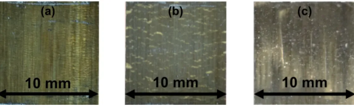
From tests of the [SG1/(C1/SG1)17] and [SG1/(C2/SG1)17] type laminates interrupted at -0.80% strain, it is shown that the typical damage mode for the hybrid configuration under compression includes carbon-ply fragmentation and localized delamination. It was possible to observe the delamination between glass/epoxy and carbon/epoxy layers due to the translucent nature of the glass/epoxy layers. The delamination area can be seen as a yellow pattern surrounding the dispersed fractures in the carbon layers and running across the width of the specimen, as shown in Figure 9. While for the [SG1/(C3/SG1)17] configuration, an interrupted test was conducted at - 0.41% well below the final failure strain of -0.50% to see if any damage had occurred, but unexpected premature failure took place. A larger delamination area near the surface of the laminate, shown as a yellow pattern, compared to the other configurations is shown in Figure 9 (c) for the [SG1/(C3/SG1)17] laminate, and glass fibre splitting was also observed.
Figure 9. Typical damage mode for the different hybrid laminates under compression at -0.80%:
(a) [SG1/(C1/SG1)17], at -0.80%: (b) [SG1/(C2/SG1)17], and at -0.41%: (c) [SG1/(C3/SG1)17].
The compression test results are summarised in Table III below.
TABLE III. SUMMARY OF COMPRESSION TEST RESULTS FOR ALL HYBRID TYPE.
Hybrid type Property Initial modulus
Ei (GPa)
Knee point strain
ε ε ε εk (%)
Knee point stress
σ σσ σk (MPa)
First load drop strain
ε ε ε ε1 (%)
Final failure strain
εε εεf (%)
[SG1/(C1/SG1)17] Average 76.50 -0.49 344 -1.67 -2.13
COV (%) (3.3) (1.7) (3.6) (10.9) (8.1)
[SG1/(C2/SG1)17] Average 97.50 -0.49 429 -1.20 -1.43
COV (%) (7.5) (5.0) (1.0) (14.2) (8.7)
[SG1/(C3/SG1)17] Average 118.90 - - -0.46 -0.46
COV (%) (5.9) - - (6.9) (6.9)
Figure 10. First load drop strain and final failure strain as a function of carbon layer thickness.
The hybrid laminates with [SG1/(C1/SG1)17] and [SG1/(C2/SG1)17] configurations show gradual failure behaviour beyond -0.49% strain up until final failure at -2.13% and -1.43% strain respectively while the [SG1/(C3/SG1)17] hybrid configuration experienced sudden failure at -0.46% strain. This behaviour is believed to be related to the different energy release rates for delamination after fibre fracture in the different hybrid laminates. As the energy release rate increases with the thickness of the carbon layer, delamination occurs at a lower strain for the hybrid with double compared with single carbon plies, while the laminate with the highest number of carbon plies delaminates as soon as fragmentation has started, followed immediately by complete failure as shown in Table III for the first load drop strain. Figure 10 gives an illustration of the reduction of first load drop strain and final failure strain with increasing carbon layer thickness.
CONCLUSIONS
The compression response of unidirectional thin ply hybrids has been established.
Gradual failure with a significant decrease in stiffness at - 0.49% strain and final failure at - 2.13% and -1.43% strain has been obtained for the [SG1/(C1/SG1)17] and [SG1/(C2/SG1)17] hybrid configuration respectively. While for the [SG1/(C3/SG1)17] configuration, sudden failure occurs at a strain of -0.46%. Even this lower strain is higher than the compression failure strain calculated from the manufacturer’s data sheet of -0.26%. The observed damage pattern for the gradual failure type laminates was carbon fibre fragmentation and dispersed delamination. The carbon layers fragmented at a higher strain than that based on the manufacturer’s data sheet. For the sudden failure type laminate, a large delamination area and fibre failure was observed.
The different damage behaviours underpin the crucial role of carbon layer thickness in unidirectional glass/carbon hybrid laminates under uniaxial compressive loading. The behaviour of different thickness hybrid laminates under compression can be qualitatively explained by the energy release rate concept.
ACKNOWLEDGEMENTS
This work was partly funded under the UK Engineering and Physical Sciences Research Council Programme Grant EP/I02946X/1 on High Performance Ductile Composite Technology in collaboration with Imperial College London. Putu Suwarta acknowledges The Directorate General of Higher Education of the Ministry of Education and Culture of the Republic of Indonesia (DIKTI) for funding through the DIKTI scholarship and the University of Bristol Alumni Foundation for providing travel funding. Gergely Czél acknowledges the Hungarian National Research, Development and Innovation Office - NKFIH for funding through grants ref. OTKA K 116070 and OTKA PD 121121, the Hungarian Academy of Sciences for funding through the János Bolyai scholarship and the Hungarian Ministry of Human Capacities- EMMI for funding through the BME-Nanonotechnology FIKP grant (BME FIKP-NAT)
REFERENCES
[1] Czél, G., M. Jalalvand, and M. R. Wisnom, 2016. “Design and characterisation of advanced pseudo-ductile unidirectional thin-ply carbon/epoxy-glass/epoxy hybrid composites,”
Composite Structures, 143:362–370.
[2] Czél, G., M. Jalalvand, and M. R. Wisnom, 2016. “Hybrid specimens eliminating stress concentrations in tensile and compressive testing of unidirectional composites,” Composites Part A, 91:436–447.
[3] Häberle, J. G. and F. L. Matthews, 1994. “An improved technique for compression testing of unidirectional fibre-reinforced plastics; development and results,” Composites, 25(5): 358–371.
[4] Czél, G., M. Jalalvand, and M. R. Wisnom, 2015. “Demonstration of pseudo-ductility in unidirectional hybrid composites made of discontinuous carbon/epoxy and continuous glass/epoxy plies,” Composites Part A, 72:75–84.
[5] Czél, G., P. Suwarta, M. Jalalvand, and M. R. Wisnom. 2017 . “Investigation of the Compression Performance and Failure Mechanism of Pseudo-Ductile Thin Ply Hybrid"
presented at the 21st International Conference on Composite Materials, August 20-25, 2017.
![Figure 1. Imperial College compression test rig [3].](https://thumb-eu.123doks.com/thumbv2/9dokorg/1424551.120743/3.918.345.562.584.913/figure-imperial-college-compression-test-rig.webp)


![Figure 6. Failure mode of [SG 1 /(C 1 /SG 1 ) 17 ] configuration at each stress level](https://thumb-eu.123doks.com/thumbv2/9dokorg/1424551.120743/7.918.213.696.313.628/figure-failure-mode-sg-sg-configuration-stress-level.webp)