Gergely Czél, Márton Bugár-Mészáros, Michael R. Wisnom
THE EFFECT OF TEST TEMPERATURE ON THE PSEUDO- DUCTILITY OF THIN-PLY HYBRID COMPOSITES
Gergely Czél1, Márton Bugár-Mészáros1 and Michael R. Wisnom2
1Department of Polymer Technology, Budapest University of Technology and Economics, Műegyetem rkp. 3., Budapest, 1111, Hungary
Email: czel@pt.bme.hu,marton.bugar.meszaros@gmail.com Web Page: http://www.pt.bme.hu/
2Bristol Composites Institute (ACCIS), University of Bristol, Queen's Building, University Walk, Bristol, BS8 1TR, United Kingdom
Email: M.Wisnom@bristol.ac.uk Web Page: http://www.bristol.ac.uk/composites/
Keywords: Hybrid composite, temperature, pseudo-ductility
Abstract
Two types of interlayer hybrid composite specimens (continuous and discontinuous) were designed and tested at three different temperatures (-50°C, 25°C and 80°C). The continuous specimens fragmented at similar strains at all temperatures and showed a linear-plateau type pseudo-ductile behaviour. The discontinuous specimens started to delaminate at different strains proving that this matrix-dominated failure mode is significantly affected by test temperature. The determined mode II critical energy release rates of the discontinuous specimens also changed by up to +35% (at low temp.) and -15% (at high temp.) compared to the room temperature reference. It was observed that at low temperature some of the specimens changed their failure mode from delamination to fragmentation which confirms that the test temperature has a strong influence on the interlaminar behaviour of the hybrids. A diagram showing the margin between the actual and the critical energy release rate of a given configuration at a given temperature is very useful for failure mode prediction.
1. Introduction
High performance polymer matrix composites are suitable for high-tech applications such as military and civil aerospace, spacecraft or motorsports due to their outstanding specific stiffness and strength, fatigue and corrosion resistance. However, a fundamental limitation of current fibre reinforced composites is their inherent brittleness which has hindered their spread towards many high volume applications. Failure of composites can be sudden and catastrophic, with little or no warning and usually poor residual load-carrying capacity if any. Thin-ply pseudo-ductile carbon/glass hybrid composites were developed recently to overcome the undesired failure mode and provide high performance together with progressive damage and clear warning before final failure. Attractive, highly non-linear stress-strain curves with linear-plateau-linear shapes have been demonstrated with unidirectional (UD) thin-ply glass/carbon [1],[2], high modulus (HM) carbon/high strength (HS) carbon hybrids [3] and quasi-isotropic (QI) HM carbon/HS carbon hybrid composites [4]. The damage mechanisms providing the favourable tensile response were identified to be low strain material fragmentation and stable delamination between the layers in the interlayer hybrids.
Besides the mechanical characterisation of the new pseudo-ductile hybrid composites at room temperature, it is important to explore their suitability for a range of operating environments. This study aims at understanding the effects of test temperature on the failure mechanisms that enable the desired pseudo-ductile stress-strain response of thin-ply glass/carbon hybrid composites.
Gergely Czél, Márton Bugár-Mészáros, Michael R. Wisnom
2. Experimental 2.1. Materials
The materials considered for design, and used for the experiments were standard thickness S2- glass/epoxy prepregs supplied by Hexcel and thin TC35 carbon/epoxy prepreg from SK Chemicals.
The epoxy resin systems in the prepregs were the aerospace grade 913 (Hexcel) and general purpose K50 (SK chemicals). Both resins in the hybrid laminates were 125°C cure epoxies, which were found to be compatible, although no details were provided by the suppliers on the chemical formulation of the resins. Good integrity of the hybrid laminates was confirmed during test procedures and no phase separation was observed on cross sectional micrographs. Basic properties of the applied fibres and prepreg systems can be found in Tables 1 and 2.
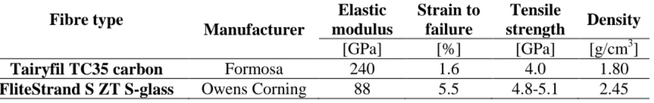
Table 1. Fibre properties of the applied UD prepregs based on manufacturer’s data
Fibre type
Manufacturer
Elastic modulus
Strain to failure
Tensile
strength Density
[GPa] [%] [GPa] [g/cm3]
Tairyfil TC35 carbon Formosa 240 1.6 4.0 1.80
FliteStrand S ZT S-glass Owens Corning 88 5.5 4.8-5.1 2.45
Table 2. Cured ply properties of the applied UD prepregs
Prepreg material Manufacturer
Nominal fibre areal
densitya
Fibre volume fractiona
Cured ply thicknessb
Initial modulusb
[g/m2] [%] [µm] [GPa]
TC35 carbon/epoxy SK Chemicals 20 47 23.7 114.3
S-glass/epoxy Hexcel 190 51 155.1 45.6
aBased on manufacturer’s data
bCalculated using manufacturer’s data
Figure 1. Tensile specimen schematic
2.2. Specimen design
Two different interlayer hybrid composite specimens were designed to analyse the two different damage modes of the developed interlayer hybrid composites (i.e. fragmentation and stable delamination) separately. Both specimen types had the same carbon/glass volume ratio, but their thicknesses were scaled by a factor of two. The thinner specimens were designed to show carbon layer
Gergely Czél, Márton Bugár-Mészáros, Michael R. Wisnom
fragmentation and stable delamination of the layers, while the thicker specimens, made with discontinuous carbon layer show stable delamination only. Fig. 1 shows the specimen geometry and the discontinuity in the centre of the carbon/epoxy layer through the width in the thicker specimens.
The following design criteria were identified earlier in [2],[3] and used here to assure fragmentation for the thin and stable delamination for the thick UD glass/carbon interlayer hybrids. Both specimen types must also be safe against premature glass/epoxy layer failure.
(i) Equation (1) was adopted as a criterion to avoid delamination by keeping the mode II energy release rate (GII) at first carbon layer fracture lower than the fracture toughness (GIIC) of the applied materials.
( )
1 1
2 2 1 1 2 2 2 2
8 2
t E
t E t E t G E
GIIC II b +
=
> (1)
Where E1, E2 are the initial moduli of the glass/epoxy and carbon/epoxy respectively, t1, t2 are the thickness of the glass/epoxy and carbon/epoxy layers respectively as shown in Fig. 1, ε2b is the breaking strain of the carbon/epoxy.
Table 3 shows that the thin specimens are safe against delamination, whereas the thick ones are borderline as the GIIC of the material pair used was determined to be around 1 N/mm. Taking into account that the carbon fibre breaking strain quoted by the manufacturer (1.6%) is significantly lower than the values according to our measurements (1.8-1.9%), the thick specimens would delaminate if they were continuous. They are expected to initiate stable delamination in discontinuous form at a strain lower than the failure strain of the carbon layer, which is the original purpose of this specimen type.
(ii) The outer, glass/epoxy layers (see Fig. 1) need to be thick and strong enough to take the full load after carbon/epoxy layer fracture and pull-out. A sufficient margin should also be allowed to account for the stress concentration in the glass/epoxy layer due to the carbon/epoxy layer fracture. Inequality (2) gives the minimum thickness of one glass/epoxy layer for a given material pair (with known failure strains and carbon/epoxy thickness) required to avoid premature glass/epoxy layer failure at first carbon/epoxy layer fracture.
(
bb b)
E t t E
2 1 1
2 2 2
1 2 -
> (2)
Where ε1b is the breaking strain of the glass/epoxy.
If, as a first approximation, the breaking strains of the carbon layer is assumed to be equal to the manufacturer’s quoted fibre failure strain, and the breaking strain of the glass layer is estimated to be 3.7% based on previous tests on similar material configurations [2], a lower bound for the glass/epoxy layer thickness can be obtained. According to Table 3, both specimen types are safe against premature glass/epoxy layer failure.
2.3. Specimen manufacturing
The glass/carbon interlayer hybrid specimens were made by stacking the specified prepreg layers on top of each other, vacuum bagging the composite plate and curing it in an autoclave according to the recommended cure cycle of the constituent prepregs (2 hours at 125°C and 0.7 MPa pressure). The discontinuities in the thicker specimens were made by manually cutting the whole carbon/epoxy layer (four thin plies) across the fibre direction with a rotary blade cutter before attaching it to the
Gergely Czél, Márton Bugár-Mészáros, Michael R. Wisnom
glass/epoxy layers. The individual specimens were cut from 300x300 mm plates with a diamond cutting wheel. 2 mm thick, 40 mm long glass fabric reinforced epoxy end-tabs were bonded on the thin specimens using Araldite 2011 and 2014 two part epoxy adhesives made by Huntsman. The specimens tested at elevated temperature were made with type 2014 adhesive which is more heat-resistant.
Tabbing was necessary as the very thin specimens were susceptible to damage from the sharp serrated grip faces.
Table 3. Specimen types
Lay-up sequence Carbon layer
Nominal thickness
Energy release rate at carbon fibre failure strain (1.6%)a
Minimum vs. nominal glass/epoxy
layer thickness
Initial modulusa
[mm] N/mm [mm] [GPa]
[S-glass1/TC352/ S-glass1] Continuous 0.358 0.480 0.045/0.155 54.7 [S-glass2/TC354/ S-glass2] Discontinuous 0.716 0.959 0.090/0.310 54.7
aCalculated using manufacturer’s data
2.4. Test method
Testing of the parallel edge specimens was executed under uniaxial tensile loading and displacement control at a crosshead speed of 4 mm/min on a Zwick Z250 type 250 kN rated universal electro- mechanic test machine with a regularly calibrated 250 kN load cell and wedge type mechanical grips.
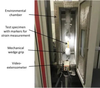
Tests of both specimen types (thin, continuous specimens to investigate fragmentation and thick discontinuous ones to assess stable delamination) were executed at -50°C, 25°C and 80°C. Non- ambient temperature testing was carried out in an environmental chamber attached to the test machine (see Fig. 2). Strains were measured using a Zwick BW40220 type video-extensometer, with a nominal gauge length of 75 mm. Markers were bonded or painted on the specimen surfaces for tracking by the extensometer. The specimens without end-tabs were tested after wrapping P80 grit size sandpaper around the ends of the specimens in contact with the grip faces (grit side to the specimen). This was enough to stop slippage of the thicker specimens from the grip and protect the surface from damage caused by the sharp grip faces. A minimum of five specimens were tested from each configuration.
Figure 2. Test setup for non-ambient temperature testing
Gergely Czél, Márton Bugár-Mészáros, Michael R. Wisnom
2.5. Results and discussion
This section summarises the results of the tensile tests at -50°C, 25°C and 80 °C for the thin, continuous and the thick discontinuous type specimens. After the tests the initial elastic modulus and the “knee point” strain and stress of the specimens were evaluated by fitting lines to different sections of the stress-extension graphs as shown in Fig. 3.
The thin, continuous specimens failed in the expected way at all the test temperatures and fragmentation of the carbon layer was observed from the knee point, with variable saturated fracture spacing as depicted in Fig. 4. The light patches show delaminated areas and dark lines correspond to residual bonding between the layers which means that fractures in the carbon layer are typically at the middle of the light regions.
Figure 3. Evaluation of the knee point strain
Figure 4. Typical specimens showing the damage pattern of thin continuous glass/carbon hybrid specimens after testing at various temperatures
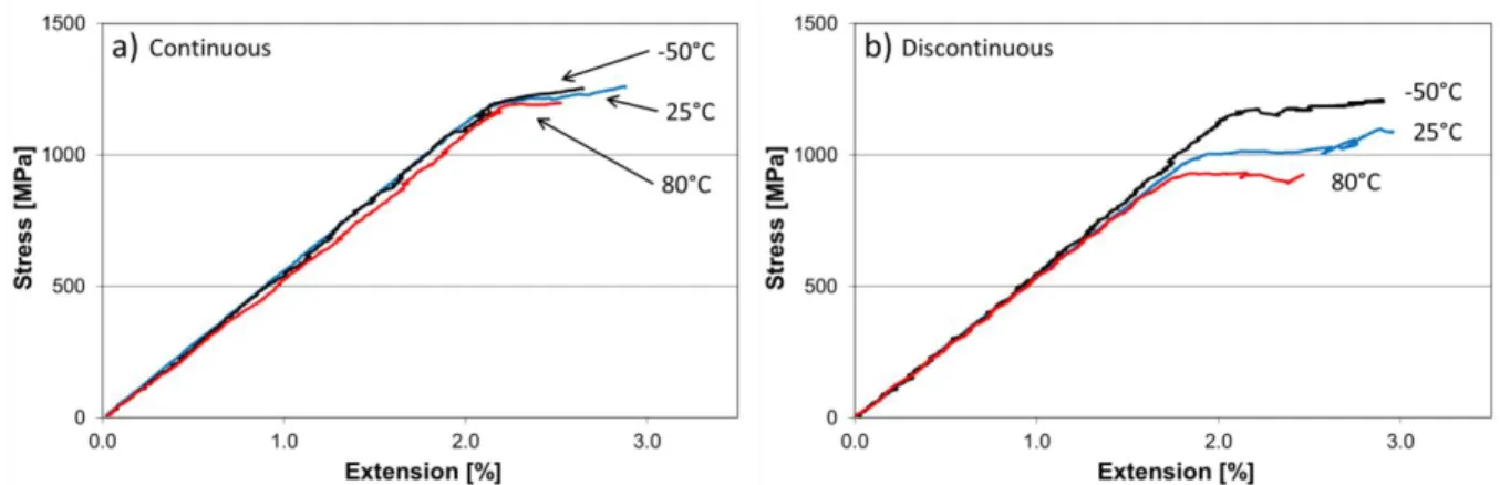
Figure 5. Mechanical response of the a) thin, continuous and b) thick, discontinuous specimens
Gergely Czél, Márton Bugár-Mészáros, Michael R. Wisnom
Fig. 5 a) shows typical stress-extension plots of three thin continuous specimens tested at different temperatures. It can be seen that the knee point has only changed slightly and the specimens developed a plateau where fragmentation of the carbon layer took place. The test was stopped before final failure as we wanted to keep the specimens in one piece for further observations and our main interest was the change in damage initiation (knee point) if any. Despite the obvious change in the damage appearance which suggests that the properties of the interfaces between the glass and carbon layers were affected, the knee point strain did not change significantly as the process was dominated by fibre fracture which is not sensitive to temperature in the range of this investigation. However the smaller fracture spacing suggests that the interlaminar shear strength (ILSS) was improved at low temperature, while the larger spacing at high temperature indicates a significant knock-down of the ILSS at 80°C even though it is 40°C away from the cure temperature (close to the expected glass transition temperature, Tg) of the composite. The summary of test results is given in Table 4.
The thick, discontinuous specimens also exhibited a controlled damage development by delamination initiation at the discontinuity (knee point) and further stable delamination up until the whole area of the gauge section (plateau). A significant variation was observed here in the delamination initiation point confirming the significant reduction in the mode II fracture toughness, GIIC with increasing temperature (see Fig. 5 b).
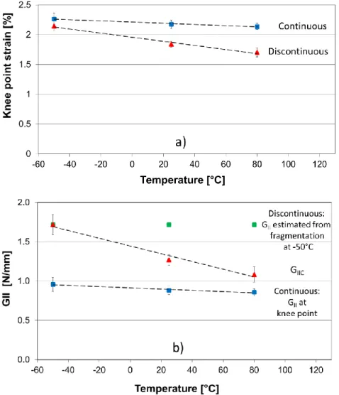
Figure 6. Temperature dependence of the a) knee point strain and b) mode II energy release rate and fracture toughness (GII and GIIC)
Gergely Czél, Márton Bugár-Mészáros, Michael R. Wisnom
Fig. 6 a) shows the summary of the variation of the damage initiation (knee point) strain- carbon layer fragmentation for the continuous and delamination initiation for the discontinuous specimens- as a function of the test temperature. As already seen in the stress-extension graphs, the temperature had a larger effect on the delamination (in the discontinuous specimens) than on the fragmentation initiation (in the continuous specimens). This is in agreement with our expectations as the delamination properties rely on the more temperature-sensitive epoxy resin, but carbon fibre failure strain is not affected significantly at the temperatures of these tests. The observed small knee point strain drop for the continuous specimens can be explained by the change in the development of multiple fractures due to change in the shear strength and fracture toughness of the resin at different temperatures. High temperature could have decreased the stress transfer capability of the resin both at fibre-matrix and ply level leading to faster development of macroscopic cracks from single fibre fractures at 80°C.
Table 4. Summary of the test results (Average of minimum five specimens is quoted where the coefficient of variation, CoV is indicated, cont. and dicont. stands for continuous and discontinuous
specimen types respectively)
Nominal thickness
Nominal width
Nominal free length
Measured modulus
from nominal thickness
Knee point strain
Knee point stress
GII for cont.
GIIC for discont.
Specimen type [mm] [mm] [mm] [GPa]
(CoV [%])
[%]
(CoV [rel.%])
[MPa]
(CoV [%])
[N/mm]
(CoV [%]) -50°C Cont.
25°C Cont.
0.358 0.358
20 20
160 160
54.4 (4.9) 54.6 (3.3)
2.26 (4.5) 2.17 (3.1)
1256.4 (4.7) 1197.4 (2.8)
0.96 (9.0) 0.89 (6.4) 80°C Cont. 0.358 20 160 52.4 (2.0) 2.14 (2.6) 1146.0 (3.0) 0.86 (5.2) -50°C Discont. 0.715 20 160 50.1 (6.0) 2.14 (3.8) 1131.9 (2.0) 1.72 (7.5) 25°C Discont. 0.715 20 160 52.3 (1.7) 1.84 (2.7) 976.7 (3.1) 1.27 (5.4) 80°C Discont. 0.715 20 160 53.8 (3.7) 1.70 (4.5) 920.1 (2.2) 1.08 (9.0)
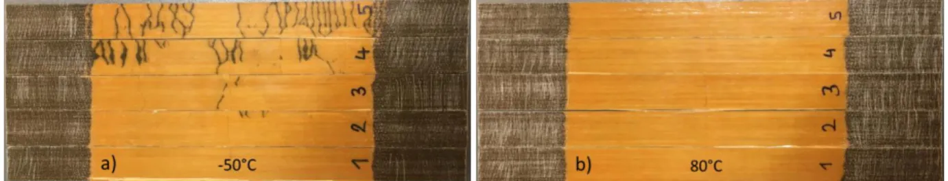
An interesting phenomenon was observed during the tests: the discontinuous specimens delaminated at 25°C and 80°C but some of them fragmented at -50°C (see Fig. 7). This suggests that the specimens at -50°C were in a condition which is very close to the borderline between fragmentation and delamination, therefore GII≈GIIC. The GII at -50°C can be used as an estimate for the whole temperature range at the same strain as this case was borderline to fragmentation in a discontinuous specimen (see green markers on Fig. 6b). With this, it is also possible to assess the margin between GII
and GIIC for the discontinuous specimens, which plays a key role in determining the damage mode.
Therefore the diagram of Fig. 6 b) was found to be a useful tool for damage mode prediction and assessment. Finally it was discovered that the test temperature may even change the damage mode of interlayer hybrid composite specimens.
Figure 7. Damage mode of the thick, discontinuous specimens at a) -50°C and b) 80°C (Behaviour at 25°C was similar to that at 80°C)
Gergely Czél, Márton Bugár-Mészáros, Michael R. Wisnom
3. Conclusions
The following conclusions were drawn from the study of UD, pseudo-ductile thin-ply carbon/glass hybrid composites at -50°C, 25°C and 80°C:
The continuous specimens retained their pseudo-ductile tensile stress-strain response at temperatures significantly lower and higher than room temperature, proving that the carbon layer fragmentation mechanism is not greatly affected in the investigated temperature range.
The discontinuous specimens delaminated stably at various strains and revealed that the interfacial properties are significantly affected by test temperature as the interlaminar fracture toughness changed +35% and -15% at -50°C and +80°C respectively compared to values obtained at room temperature.
A change in damage mode was found at -50°C as some of the discontinuous specimens fragmented. This demonstrated the consequence of the large change in interlaminar fracture toughness with test temperature.
A diagram containing the mode II energy release rates of both the discontinuous and continuous specimen series as well as the mode II fracture toughness values calculated from the discontinuous specimens proved to be a powerful design tool. It shows the margin between GII and GIIC at various temperatures which plays a key role in governing the damage mode.
Acknowledgments
This work was funded by the Hungarian National Research, Development and Innovation Office - NKFIH through grant ref. OTKA K 116070, by the Hungarian Ministry of Human Capacities- EMMI through the BME-Nanonotechnology FIKP grant (BME FIKP-NAT) and by the UK Engineering and Physical Sciences Research Council through Grant EP/I02946X/1 in collaboration with Imperial College London. Gergely Czél acknowledges the Hungarian Academy of Sciences for funding through the János Bolyai scholarship and NKFIH for funding through grant ref. OTKA PD 121121.
References
[1] G. Czél, M.R Wisnom. Demonstration of pseudo-ductility in high performance glass-epoxy composites by hybridisation with thin-ply carbon prepreg. Composites Part A: Applied Science and Manufacturing, 52:23-30, 2013.
[2] G. Czél, M. Jalalvand, M.R Wisnom. Design and characterisation of advanced pseudo-ductile unidirectional thin-ply carbon/epoxy-glass/epoxy hybrid composites. Composite Structures, 143:362-70, 2016.
[3] G. Czél, M. Jalalvand, M.R Wisnom, Czigány T. Design and characterisation of high performance, pseudo-ductile all-carbon/epoxy unidirectional hybrid composites. Composites Part B: Engineering, 111:348-356, 2017.
[4] G. Czél, T. Rev, M. Jalalvand, M. Fotouhi, M.L. Longana, O. J. Nixon-Pearson, M.R. Wisnom.
Pseudo-ductility and reduced notch sensitivity in multi-directional all-carbon/epoxy thin-ply hybrid composites. Composites Part A: Applied Science and Manufacturing,104:151-164, 2018.