COMPARISON OF DIFFERENT INTERFACIAL ENGINEERING METHODS TO ACHIEVE PSEUDO-DUCTILE BEHAVIOUR OF
CARBON FIBRE REINFORCED POLYMER COMPOSITES
B. Magyar1, G. Szebenyi2*, T. Czigany1,3
1 Department of Polymer Engineering, Faculty of Mechanical Engineering, Budapest University of Technology and Economics, Budapest, Hungary, magyarb@pt.bme.hu
2 Department of Polymer Engineering, Faculty of Mechanical Engineering, Budapest University of Technology and Economics, Budapest, Hungary, szebenyi@pt.bme.hu
3 MTA–BME Research Group for Composite Science and Technology, Muegyetem rkp. 3., H-1111 Budapest, Hungary; Department of Polymer Engineering, Faculty of Mechanical Engineering,
Budapest University of Technology and Economics, Budapest, Hungary, czigany@pt.bme.hu
* Corresponding author (szebenyi@pt.bme.hu)
Keywords:interfacial engineering, carbon fiber reinforced composites, pseudo-ductile behavior
ABSTRACT
In this paper we compared different types of interfacial engineering methods to achieve pseudo- ductile behavior in carbon fiber reinforced polymer composites. We achieved this behavior with the help of fused deposition modelling (FDM) using poly(ε-caprolactone) (PCL) whereas we printed this material onto the surface of the carbon fiber (CF) weave as the interface engineering material to induce the pseudo-ductile behavior. Furthermore, we investigated the effect of surface filling (SF) as well. In the other hand we investigated the feasibility of a new method whereas we used CO2 laser to burn of the sizing from the CF surface. Both methods aim to achieve the pseudo-ductile behavior with interfacial engineering where tailored weaker zones between the matrix and the fiber reinforcement could be created. The task for these zones is to slow down the crack propagation during the damage process. In all occasions the different amount of PCL as an interfacial engineering material had effects on the pseudo-ductile behavior and with scanning electron microscopy (SEM) we also showed the feasibility of the CO2 laser for surface treatment as well.
1 INTRODUCTION
Carbon fibre reinforced thermoset matrix polymer composites have widely spread across the world because of their wide range of capabilities. In the last decades some structural steel structures have been replaced by their fiber reinforced competitors. Still there are major issues with the damage progression and the final failure modes. It is well known that after reaching the maximal load capacity of the composites the failure happens instantly without any significant sign due to their brittle behavior. In these cases, the most common damage mode which leads to the final form of failure is fiber breakage which has the lowest energy absorption capability of the various damage modes.
Because of this, a smart composite which could respond in another way, by a different damage mechanism, receives more and more attention.
There are already some promising methods to increase the ductile behavior of carbon fiber reinforced polymer composites (CFRPs). Each approach starts with one of the composite's components. One of the oldest methods is to use hybrid reinforcements such as glass/carbon fiber or aramid/carbon fiber. Due to the hybridization the different properties of the fibers can cause a more ductile behavior [1, 2]. In addition to the fiber hybridization, the ductile behavior can also be achieved by using slightly deviated orientation in the laminate [3] or by using short fibers instead of long, infinite fibers.
The formation of dense crosslinking in thermoset matrices results in a very rigid and brittle material which is susceptible to crack growth. This behavior can be modified with additives like thermoplastic
Balazs Magyar Gabor Szebenyi Tibor Czigany
materials which can dissolve in it, causing locally toughened resin [4, 5] and this can be achieved with rubber additives, like core-shell rubbers (CSR) [6, 7].
The interaction between the fiber and matrix is also important. Thanks to the proper interfacial adhesion the matrix can transfer the load to the reinforcements. With different types of sizing zones, different interfacial properties could be achieved along the length of the fibers. Some developments used interpenetrating polymeric networks [8] whereas the reinforcements are specifically sized for good adhesion to only one of the matrix components.
These methods can be used simultaneously for a hybrid toughening mechanism. Every approach has its own benefits but still there is no universal answer to complete the task.
In the case of our proposed tailor-made interfacial adhesion method, the crack will not spread to the fiber along the fiber length, instead it will bypass or even it could stop as well which could cause only local delamination [9]. With this kind of behavior, the energy absorption is much more favorable, and the characteristic damage state curve of the composite is stretched. That means the composite acts more reliable and the chance for the catastrophic failure is reduced.
The aim of this paper is to investigate the feasibility of pseudo-ductile composites via different type of interfacial engineering. We produced two type of interfacial engineering, the first that we performed was an additive interfacial engineering method where we printed patterns on to the CF surface. The second type of interfacial engineering was a removal method, where we burned off the sizing from the CF surface.
2 EXPERIMENTAL
To achieve the required behavior, we used two types of interfacial engineering methods. One of the methods was fused deposition modelling (FDM) technology, where we printed patterns on the surface of the unidirectional (UD) carbon fiber reinforcement. We used CraftBot Plus FDM printer for this method. For the printing we used poly(ɛ-caprolactone) (PCL) filaments. With the printed PCL, we created weaker interfacial adhesion zones along with the pattern (Fig 1.). The PCL material also dissolves in the matrix, so no further phase appears in the composite. We already showed the feasibility of this method in our previous paper [9].
Figure 1: Designed microcell of modified interface adhesion composite, where the printed PCL material weakens the interfacial adhesion
In the other aspect of this study, we used a material removal technique as a toughening mechanism (Removal Interfacial Engineering – RIE) instead of the additive technology (Additive Interfacial Engineering - AdIE). In this method we removed the sizing from the CF fibers, therefore in those regions the connection between the resin and the reinforcement could be locally weakened. For the removal we used LASER surface treatment, where the sizing was burnt off in several locations along the reinforcement length. For the RIE we used Alfa LCE-2 LASER cutter.
We used the IPOX ER 1010 (IPOX Chemicals Kft., Budapest, Hungary) DGEBA-based epoxy resin (EP) as the matrix of the composite laminates, with the IPOX MH 3124 amine-based curing agent. The mixing weight ratio was 100:35, according to the producer’s recommendation. Curing this
eMorph175N05 (Shenzhen Esun Industrial Co. Ltd., Shenzhen, China) PCL filament. We chose PCL because it is soluble in the matrix, it is easier to process than other thermoplastic additives due to its lower melting temperature, and because it is a biomaterial, so it is not harmful to the environment, unlike many high-performance additives. The diameter of the filament was 1.75 mm (melting temperature, Tm = 60 °C, print temperature: >80 °C).
2.1 Additive interfacial engineering
The six-layer unidirectional composites were created by hand layup followed by vacuum pressing.
The reinforcing layers were impregnated with the EP resin with peel plies on both the top and bottom layers to ease removal from the PET film that covered the glass sheet mould. A vacuum bag was built over the laminate to provide uniform pressure and a high fiber content. A vacuum of 0.8 bar was applied for 20 minutes at room temperature, then the samples were put in the heat chamber at 80 °C for 1 hour for curing. In case of interlaminar-patterned samples 5 patterned and 1 neat layer was laid up in a way that the patterns were present in all interlayers. It should be kept in mind that under this condition PCL is only partly dissolved in the EP. The laminate thickness of the reference composite was 2.9 mm, the thickness of the CF/EP composites with the PCL interphase was 3.3 mm. The specimens were cut from the laminates by a Mutronic Diadisc diamond disc saw according to the standard specifications.
The possibility and feasibility of this method has already been investigated in our previous papers, where we also investigated the effect of different pattern layouts on the pseudo ductile behavior. In this paper we investigated the effect of surface filling of mechanical properties. The main goal was to achieve a weaker interfacial connection between the reinforcement and the matrix structure. Fig 2.
shows the desired IE pattern, and Table 1. shows the parameters of the pattern.
Figure 2: Diagonal interfacial pattern Surface filling [%] 5 10 15 Line width [mm]
0.2 0.4 0.6
Table 1: Pattern’s line width at different surface filling.
2.1.1 Flexural test
We investigated the mechanical behavior by static and dynamic tests. Three-point flexural tests were carried out as a static test, in which the interlaminar failure mechanism could be investigated, and
Balazs Magyar Gabor Szebenyi Tibor Czigany
by calculating the amount of absorbed energy we could examine the change in toughness. The three- point bending tests were performed on standard 100 mm long, 15 mm wide specimens with a Zwick Z020 computer-controlled universal tester according to EN ISO 14125 at room temperature. The tests were performed with 80 mm support span and at a test speed of 2 mm/min.
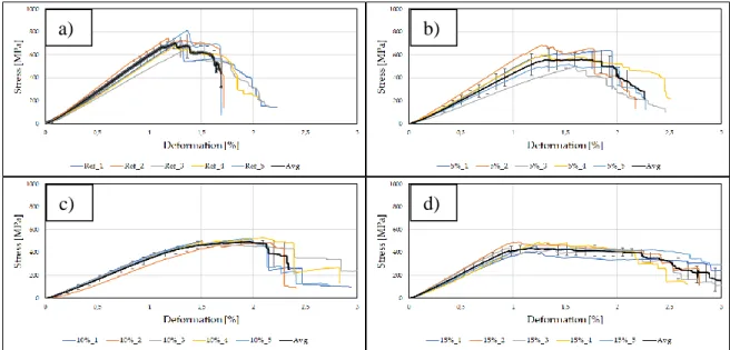
Figure 3: 3-point binding test curves at different surface filling contents with averages and standard deviations; a) reference; b) 5%; c) 10%; d) 15%.
Table 2. shows the bending test results. From that the surface filling has no significant effect on the flexural modulus (ANOVA method with 95% confidence interval). On the other hand, it had an effect on the maximal stress. With increased SF the maximal stress has dropped as well but the final failure happened at a higher deformation level and a lower stress level as well.
Surface filling [%]
0 5 10 15
E [GPa] 49.8±7.3 47.1±7.3 45.5±8.7 39.9±5.6
σm [MPa] 736.3±49.0 642.2±25.1 587.9±77.9 457.6±36.0
εm [%] 1.3±0.1 1.3±0.1 1.2±0.1 1.2±0.1
σb [MPa] 145.6±50.8 118.0±21.5 115.6±30.0 113.6±28.1
εb [%] 2.0±0.2 2.3±0.2 2.6±0.2 3.1±0.3
Table 2: 3-point bending test results where ”E” is the Young’s modulus, “σm” is the maximal stress,
“εm” is the deformation at the maximal stress, , “σb” is the stress at break and “εb” is the elongation at break, “SAE” is the specific absorbed energy and DI is the ductility index.
From the curve progression (Fig. 3) it is visible that after reaching the maximal stress values a gradual damage progression appeared in the modified samples. It is clearly visible that the increased SF had an effect on the progression as well, with increasing SF the curves started to have longer plateaus. The reference specimens after reaching the maximal stress do not exert any resistance, they suddenly broke there is no more potential for further significant deformation. In case of the modified samples, after reaching this limit, they were able to withstand a prolonged failure. In order to have more information about the absorbed energy during the damage progression we integrated the the area under the curves.
From the integral we gained the specific absorbed energy (SAE). From Fig. 4. a) it can be observed that the amount of absorbed energy has increased with the increased SF as well.
a) b)
c) d)
Figure 4: Ductility results at 3point bending tests; a) Specific Absorbed Energy results calculated from the 3-point bending test; b) Ductility index results
The SAE values alone have not much further information about the ductile behavior itself. To investigate the SF effect on the ductility we used the Ductility Index (DI). DI can set a value between 0 and 1, where results close to 0 show tougher behavior, while values near 1 show brittle behavior.
With the increased SF we got closer to a ductile behavior which can also be seen on the curve progression as well (Fig. 4. b).2.1.1 Dynamic test
The dynamic test was carried out in the form of flatwise Charpy impact tests as a dynamic counterpart to the static three-point bending tests. The instrumented impact tests were performed according to EN ISO 179 on standard 80 mm long (span length: 62 mm), 10 mm wide specimens at room temperature with a Ceast Resil Impactor Junior instrumented pendulum equipped with a 15 J maximum impact energy hammer and a Ceast DAS 8000 data acquisition system. The impact velocity was 3.7 m/s.
The same phenomenon can be seen on both the SAE and DI values as well. With increased SF the SAE values increased and the composites acted more ductile as well. This behavior connected to the crack propagation. Also, with the IE material we created PCL reach interphases where the resin toughened as well (Fig. 5).
Figure 5: Charpy impact test results with different surface filling contents. a) Specific Absorbed Energy values; b) Ductility Index values
The results show that the increase of the SF have increased simultaneously the specific absorbed energy as well, which indicates a better pseudo-ductile behavior (Fig. 5. a). It is also worth examining the ductility index to support this more ductile behavior. Fig. 5. b shows the change in the ductility index as function of surface filling. The composites behaved more ductile by increasing the surface filling, since we made larger zones with less interfacial adhesion between the resin and the reinforcement. Due to these zones the crack propagation slowed down; the composite was able to absorb more energy during the damage process.
a) b)
Balazs Magyar Gabor Szebenyi Tibor Czigany
2.2 Removal of interfacial engineering
In our other experiment we tested the Removal Interfacial Engineering (RIE). With this method we burned off the sizing from the CF surface. There are several techniques to ease off the sizing from the reinforcement but most of them remove it entirely and to and their implementation is also difficult.
Mainly these techniques remove the sizing by chemical dissolution or burning. With the CO2 LASER we could produce similar patterns like with the AdIE without adding any plus material into the composite. In this paper we investigated the feasibility of this new method to achieve the pseudo- ductile behavior. We used the same reinforcement, sized for epoxy resin in this part of the study. In our previous paper we investigated the effect of different sizing where we experienced if we used a CF which had sized to epoxy had weaker performance with PA matrix compared to a CF which was sized to the exact matrix [10]. With weaker interfacial adhesion zones, we could achieve significant improvement in the pseudo-ductile behavior.
For the CO2 surface treatment, we used Alfa LCE-2 LASER cutter. The device has a 60W output power. We used different output power levels ranging from 5 to 25%. We burned the reinforcement in a 3 mm line which was perpendicular to the direction of the UD fibers.
In the first step, we tested the reinforcement at a 5% power output and then proceeded with 5%
increments. However, already at 25% power output, we have observed that the fibers are degraded, therefore we did not carry out the experiments at a higher rate (Fig. 6).
Figure 6: Scanned pictures of the CO2 laser treated surface at different power output levels, a) the front surface which is treated by the laser directly; b) the backside of the reinforcement.
Also, it is clearly visible that the backside of the reinforcement was also affected by the CO2 laser as well, thanks to the thermal conductivity of carbon fibers.
2.2.1 Scanning Electron Microscope
We conducted scanning electron microscopy (SEM) with JEOL JSM 6380LA to have a better picture from the effect of the surface treatment we used. It is visible in Fig. 7. that the 5% of power output increments had significant effect on the sizing and on the degradation level of the fibers as well.
At the reference reinforcement it is visible that the fiber surface is smooth compared to the treated fibers. In case of the lower power output (5%, Fig. 7. b) we were only able to melt the knitting fibers.
At 10% power output the laser burned off the sizing and also started to degrade the fibers itself. The fibers diameters also decreased. At 15% of power output (Fig. 7. d) some fibers were completely cut through. This phenomenon is more noticeable by increasing the performance (Fig. 7. f, g). At 25%
power output the basically almost cut through the reinforcement.
, Figure 7: SEM pictures from the RIE reinforcement (500x magnification) at different level of power
outputs; a) reference; b) 5%; c) 10%; d) 15%; e) 20%; f) 25%.
It can be said that in the case of the non-treated reinforcement the surface of the reinforcement is smooth thanks to the sizing coat. Fig. 8. shows 1000x magnified SEM pictures where it is clearly visible that the treated fibers got rough surface. It can be inferred from this that the sizing in these regions has been removed. As a result, the adhesion conditions at the treated surfaces were changed.
This altered connection allows a similar damage mechanism, as described above. It can also be observed that the diameter of the fibers has also changed where they have undergone treatment. These places may become weak points later.
c) d)
e) f)
Balazs Magyar Gabor Szebenyi Tibor Czigany
Figure 8: SEM pictures from the surface roughness of the reinforcement (1000x magnification); a) reference; b) 15%.
3 CONCLUSIONS
Both the presented additive and removal technology uses the interfacial engineering method to reach the desired pseudo-ductile behavior. In the case of the RIE method further research is needed to prove this claim. With both interfacial engineering method, the favorable behavior could sought in the crack progression mechanism. During the damage progression the weaker zones could slow or even stop the crack growth via local damages (local delamination). Thanks to this metal like damage progression may appear, which is visible in the three-point binding curves where a plateau appeared after the maximal stress. In this horizontal part of the curves, essentially continuous brittle fractures and delamination appeared, however, their appearance has been gradual, with less energy release.
Even though both technologies use interfacial engineering to achieve the pseudo-ductile behavior, they are based on two different concepts. With additive IE we used FDM technology to print on the reinforcement. With the printed material we also toughened the resin locally. It could be a drawback as well since in this case there is an extra material in the composite as well, however, thanks to this material, the composite becomes partially healable, which we have already studied in our previous paper [9]. At the abrasive technology we burned off the sizing from the reinforcement surface. With this we achieved similar interfaces where we created locally weakened zones which we proved as well.
ACKNOWLEDGEMENTS
The authors would like to sincerely thank late Prof. Dr. h.c. mult. József Karger-Kocsis for his support and valuable comments which serves as a solid foundation of our research. This research was supported by The National Research, Development and Innovation Office (NKFIH FK 124352 and NVKP_16-1-2016-0046), and by the Higher Education Excellence Program of the Ministry of Human Capacities in the frame of Nanotechnology research area of Budapest University of Technology and Economics (BME FIKP-NANO), further the National Research, Development and Innovation Fund (TUDFO/51757/2019-ITM, Thematic Excellence Program). Balázs Magyar acknowledges the financial support received through ÚNKP-18-3-1 Scholarship New National Excellence Program of the Ministry of Human Capacities.
REFERENCES
[1] Y. Swolfs, Y. Geboes, L. Gorbatikh, S. T. Pinho: The importance of translaminar fracture toughness for the preparation impact behaviour of woven carbon/glass hybrid composites.
Composites: Part A, Vol. 103, 2017 pp 1-8 (doi: 10.1016/j.compositesa.2017.09.009).
a) b)
[3] J. D. Fuller, M. Jalalvand, M. R. Wisnom: Combining fibre rotation and fragmentation to achieve pseudo-ductile CFRP laminates. Composite Structures, Vol. 142, 2016 pp. 155-166 (doi:
10.1016/j.compstruct.2016.01.073
).
[4] R. A. Pearson, A. F. Yee: Toughening mechanisms in thermoplastic-modified epoxies: 1.
Modification using poly(phenylene oxide). Polymer, Vol. 34, 1993 pp. 3658-3670 (doi:
10.1016/0032-3861(93)90051-B
).
[5] S. Grischuk, O. Gryschuk, M. Weber, J. Karger-Kocsis: Structure and toughness of polyethersulfone (PESU)-modified anhydride-cured tetrafunctional epoxy resin: effect of PESU molecular mass. Journal of Applied Polymer Science, Vol. 123, 2011, pp. 1193-1200 (doi:
10.1002/app.34610).
[6] J. N. Sultan, F. J. McGarry: Effect of rubber particle size on deformation mechanisms in glassy epoxy. Polymer Engineering & Science, Vol. 13, 1973, pp. 29-34 (doi: 10.1002/pen.760130105).
[7] S. A. Ngah, A. C. Taylor: Toughening performance of glass fibre composites with core-shell rubber and silica nanoparticle modified matrices. Composites: Part A, Vol. 80, 2016, pp. 292-303.
[8] J. Karger-Kocsis, O. Gryshchuk, J. Fröhlich, R. Mülhaupt: Interpenetrating vinylester/epoxy resins modified with organophilic layered silicates. Composites Science and Technology, Vol. 63, 2003, pp. 2045-2054 (doi: 10.1016/j.compositesa.2015.10.036).
[9] G. Szebényi, T. Czigany, B. Magyar, J. Karger-Kocsis: 3D printing-assisted interphase engineering of polymer composites: Concept and feasibility. Express Polymer Letters.
2017;11:525-30 (doi: 10.3144/expresspolymlett.2017.50).
[10] G. Szebényi, B. Magyar: Effect of fiber sizing on the interlaminar properties of polyamide matrix composites. IOP Conference Series: Materials Science and Engineering, Vol. 426, 2018 (doi:
10.1088/1757-899X/426/1/012044).

![Figure 2: Diagonal interfacial pattern Surface filling [%] 5 10 15 Line width [mm] 0.2 0.4 0.6](https://thumb-eu.123doks.com/thumbv2/9dokorg/1331846.107799/3.893.260.653.662.932/figure-diagonal-interfacial-pattern-surface-filling-line-width.webp)