Composites Science and Technology 215 (2021) 109002
Available online 27 August 2021
0266-3538/© 2021 The Author(s). Published by Elsevier Ltd. This is an open access article under the CC BY-NC-ND license
(http://creativecommons.org/licenses/by-nc-nd/4.0/).
Metal-alike polymer composites: The effect of inter-layer content on the pseudo-ductile behaviour of carbon fibre/epoxy resin materials
B. Magyar
a, T. Czigany
a,b, G. Szeb ´ enyi
a,*aDepartment of Polymer Engineering, Faculty of Mechanical Engineering, Budapest University of Technology and Economics, Muegyetem rkp. 3, H-1111, Budapest, Hungary
bMTA–BME Research Group for Composite Science and Technology, Muegyetem rkp. 3., H-1111, Budapest, Hungary
A R T I C L E I N F O Keywords:
Interface Damage tolerance Durability 3D printing Repairability
A B S T R A C T
With interfacially engineered pseudo-ductile carbon fibre reinforced polymer composites, a higher energy ab- sorption capacity and metal-like stress-strain response can be achieved during failure. Due to incorporated inter- layer additives deposited with fused filament fabrication, locally weakened zones can be printed on the surface of the reinforcing material, which provides better energy absorption capability during the composite laminates’ damage process by the alteration of crack propagation. The reason for this phenomenon is that cracks near the inter-layered zones require more energy to propagate, which delays the onset of final failure in the form of local damage. The modified layers are then infiltrated with an amine-cured epoxy by vacuum assisted infusion. The change in pseudo-ductile behaviour as a function of the interfacial additive content was investigated, along with the change in mechanical properties.
The stress-strain relationship was determined by various tests, quasi-static and dynamic, from unmodified composites (0% interlayer used) up to 100% interlayer content (i.e. polymer film) between the matrix and the reinforcement. We have investigated a method to repair the specimens after the bending tests via melting the thermoplastic interlayer. The results show that with the use of interlayer material, the critical stress intensity factor increased, and ductile behaviour improved thanks to the altered crack propagation.
1. Introduction
Composite materials are used in many new applications due to their favourable mechanical properties, but their spread is still limited.
Although these materials have excellent strength and stiffness, their ductility is limited [1–3]. Lack of ductility is an especially serious problem with carbon fibre reinforced composites with a thermoset matrix.
The ductile behaviour of classical metals does not exist in these composite systems. In carbon fibre reinforced composites, no plastic deformation occurs, which would absorb significant energy during failure. In the classical case, after reaching a critical load, the composite system shows failure without further deformation with a high energy release rate [4–6] and catastrophic fracture. This linear characteristic and the associated brittleness is what drastically diminishes the reli- ability and further spread of these systems presently. However, plastic-like deformation can be achieved by modifying the composite phases in different ways, as a result of which the stress-strain
relationship can be divided into parts—a linear elastic region, followed by a plastic-like response. This phenomenon is called pseudo-ductility, since the nonlinear relationship appears not as a result of plastic deformation but of other phenomena [7–9]. Due to this nonlinear rela- tionship, composites can absorb more energy during failure, with less energy being released at the final failure.
Modifying the connection between the reinforcing layers provides a possible solution for the problem. In non-three-dimensional reinforce- ment, interlaminar toughness and shear strength play a key role in ul- timate failure. Even at low-velocity impacts or low load levels, layer delaminations with matrix microcracks can appear, significantly reducing the structure’s load capacity. Composites modified by inter- layer techniques exhibit more ductile behaviour, providing greater deformation and energy absorption. A wide range of materials can be used for the inner layer, from a thin polymer layer to other types of reinforcements (glass, aramid), thus forming hybrid systems and even nano-reinforcement is an option to modify interlayer properties.
Arai et al. [10] used carbon nanofabric as an interlayer between
* Corresponding author.
E-mail address: szebenyi@pt.bme.hu (G. Szeb´enyi).
Contents lists available at ScienceDirect
Composites Science and Technology
journal homepage: www.elsevier.com/locate/compscitech
https://doi.org/10.1016/j.compscitech.2021.109002
Received 20 April 2021; Received in revised form 12 July 2021; Accepted 15 August 2021
unidirectional (UD) carbon fabrics. In mode I and mode II fracture tests, they found that fracture toughness increased compared to the neat carbon fabric samples. In the first mode tests, they showed that fracture toughness depends on the surface density of the carbon nanao-fibre (CNF) layer. Wang et al. [11] used poly-(ethylene co-methyl acrylate) (EMA) as the thin inner layer. Due to the EMA layers located between the carbon fibre (CF) layers, the energy release rate (G1c) increased significantly with decreasing shear strength in Double-Cantilever Beam (DCB) tests. Mouritz et al. [12] also used a thermoplastic interlayer additive to test repairability with the use of an interlayer material. They found that the material bonded the damaged surfaces when the delaminated surfaces were pressed together, with the appropriate pressure and at the right temperature above the melting point of the thermoplastic additive. Zhang et al. [13] investigated the possibility of an interlayer technique with printed polymethyl methacrylate (PMMA).
On glass fibre-reinforced prepregs, PMMA was applied in various pat- terns by inkjet printing, which functioned as a microphase. In terms of mechanism, the ductile behaviour can be attributed to the crack-stopping of PMMA particles, which are able to deform during the propagation of cracks, thus absorbing additional energy from the com- posite. Kostopoulos et al. [14] investigated the improvement provided by supramolecular polymers on composite materials with Mode II failure tests. The supramolecular polymer was placed between the carbon fibre epoxy prepreg layers in a film about 120 μm thick and 20 mm wide. The maximum load (Pmax) doubled for the hybrid composite, and GIIc
showed a similar increase. X. Hu et al. [15] placed ultra-thin 13 μm thick short-fibre aramid layers between the carbon layers. The aramid layers caused an increase in flexural strength. However, gradual failure did not occur in their studies; the specimens suffered brittle failure after maximum load. B. Liu et al. [16] used multi-walled carbon nanotubes and multilayer graphene to improve interlaminar shear strength. The observed behaviour of the composite was presumably due to more stable crack propagation. With these interlayer techniques, interlaminar frac- ture toughness can be enhanced, but thermoplastic interlayers show better results compared to thermoset and fibrous interlayer materials, due their higher energy absorption capacity.
Mullin et al. [17,18] investigated coated boron fibres. They created regions along the length of the fibres, which had varying quality of interfacial adhesion. Higher and lower interfacial shear strength zones appeared. Due to the different zones, crack propagation changes, since in the zones with weaker adhesion, the crack does not spread to the fi- bres but results in local damage. Such special coating has also been used by Atkins et al. [19–21], who investigated randomly placed coating zones. Their coating also formed two separate zones along the length of the fibres. Using a similar technology like the coating technology, they achieved a 400% improvement in fracture toughness with a tensile strength loss of less than 10%. They used a boron fibre reinforced polymer (BFRP) composite with 80% polyurethane varnish (PUV) coated boron fibre; they did the same with vacuum-sealing silicone grease (SVG), but in this case, no such significant improvement was found.
With interlayer technologies, interlaminar fracture toughness can be increased in most cases. Also, these technologies increased the energy absorption capacity during failure. However, global ductile behaviour, a metal-like stress–strain response with gradual failure did not appear in all cases, i.e. failure remained brittle. The absorbed energy increased due to the increased interlaminar fracture toughness. An intermediate solution could be when connection was not changed between the layers but between fibres and matrix within a layer. The surface treatment technologies necessary to achieve this effect are complicated, and various chemicals used in the process are considered harmful to the environment.
Our research examines the effect of the beneficial synergic effects of the two technologies (interlayer and surface treatment). For this, an interlayer technique was used, with a simultaneously alternated inter- facial shear strength along the length of the fibres. This method is based
on fused filament fabrication (FFF) printing, where a thermoplastic material was printed on the surface of the fabrics, which is able to change the connection between the fibres and the matrix [22], as well as the interlayer properties. In the present research, the effect of the con- centration of this interlayer material was investigated on the mechanical properties of the composites.
2. Materials
IPOX ER 1010 (IPOX Chemicals Kft., Budapest, Hungary) DGEBA- based epoxy resin (EP) with IPOX MH 3111 curing agent was used.
According to the producer’s recommendation, we used a mixing weight ratio of 100:75. The EP was cured at 90 ◦C. Fibre reinforcement was PX35FBUD0300 (Zoltek Zrt., Nyergesújfalu, Hungary) stitch-bonded unidirectional carbon fabric (309 g/m2 surface weight), consisting of Panex35 50k roving. For the interlayer, which was printed on the sur- face of the unidirectional carbon weave, we used eMorph175N05 (Shenzhen Esun Industrial Co. Ltd., Shenzhen, China) poly (ϵ-capro- lactone) (PCL) filament. We chose PCL because it is soluble in the matrix, thus it does not create a new phase [23,24]. Filament diameter was 1.75 mm (melting temperature, Tm =60 ◦C, print temperature: 180 ◦C).
3. Manufacturing of the composite laminates
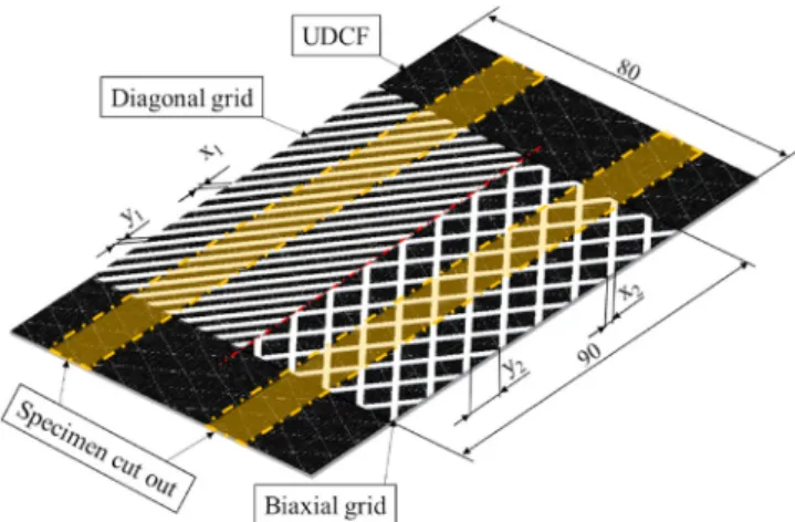
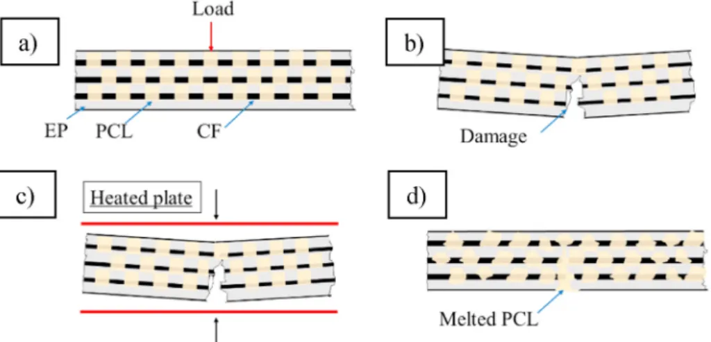
The interfacial grid patterns as an interlayer were manufactured by fused filament fabrication (FFF), PCL was used as a surface modifier to create a weakened bond between the epoxy matrix and the reinforce- ment [22]. The basic geometry of the applied pattern is shown in Fig. 1 with the dimensions in Table 1. Surface filling (SF) content shows the amount of PCL used as an interlayer. SF is calculated with Eq. (1), SF=APCL
A ⋅100[%] (1)
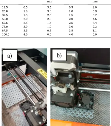
where APCL is the area covered by the interlayer modifier PCL in mm2, and A is the area covered (80 ×90 mm). A 100% SF means that the 80 mm ×90 mm area was completely covered with the PCL additive. This grid was chosen based on our previous experimental results [22,25]. The increased surface fill rate was achieved by increasing the thickness of each zone. The height of the grids was 0.2 mm. In addition to the di- agonal pattern, we also investigated another biaxial pattern. The biaxial pattern makes it more likely that a multi-directional crack will encounter a modified interface zone. As a result, the amount of fibre fracture can be reduced. Instead of fibre fractures, more local delami- nation zones may occur, which can result in a more pseudo-ductile failure process. We did FFF printing with a Craftbot Plus 3D printer.
Following surface grid printing (Fig. 2), preforms were prepared for
Fig. 1. Interfacial grid patterns on unidirectional carbon fibre (UDCF) weave as interlayer and local adhesion modifier.
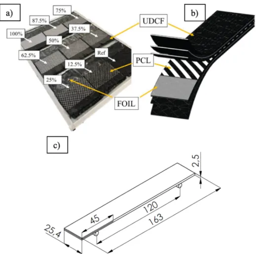
vacuum infusion with a hydraulic press. A Collin Teach-Line Platen Press 200E was used with a surface pressure of 4.5 MPa for 1 min and a temperature of 80 ◦C. The parameters were chosen so that the di- mensions of the pattern are not changed; the goal was to cover the fibres with PCL and control the thickness of the composite specimens (with the pressed grids, the PCL also covers the whole circumference of the CF instead of covering only the top of it). Afterwards, the composite lami- nates were manufactured via vacuum infusion. A sheet glass mould was used for vacuum infusion with peel plies on both sides to ease removal from the poly(ethylene terephthalate) (PET) film that covered the mould. Above the peel plies, a resin guide net was placed, which spread the resin. A vacuum bag was built over the laminate to provide uniform pressure and high fibre content. A vacuum of 0.8 bar was applied for 3 h in a drying oven at 90 ◦C. In the case of samples with interlaminar patterns, five patterned layers and one neat layer were laid up so that the patterns were present in all the interlayers. Under these conditions, PCL is only partly dissolved in the EP and there was no PCL spread on the surface of the CF, as confirmed in our previous paper [22] The speci- mens were cut from the laminates with a Mutronic Diadisc diamond disc saw according to the standard specifications.
4. Experimental
4.1. Mode II end-notched flexure test
During the manufacturing of end-notched flexure (ENF) specimens, an artificial defect was placed between the predetermined layers (with the help of a foil, resulting in artificial layer separation between the 3rd and 4th layer of the 6-layer composite), thus mode II failure mode
(Fig. 3) could be examined. Interlaminar fracture toughness values were examined while the PCL ratio was varied. Test speed was 5 mm/min, the distance between the supports was 120 mm. Specimen length, width and thickness were 163 mm, 25.4 mm and 2.5 mm, respectively. Artificial delamination length was 45 mm.
One side of the specimens was painted after fabrication, also lines were painted with 2 mm spacing from the artificial defect on the side of the specimen to monitor crack propagation over time. The test was recorded with a Canon 800D digital camera. Based on the video, the propagation of the crack was evaluated in time.
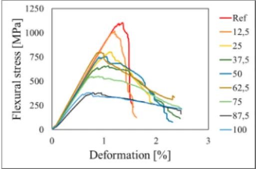
As the ENF bending force-deflection curves (Fig. 4) indicate, the presence of PCL in the specimens reduces the first force peak. The most significant decrease occurred in the sample with the lowest PCL ratio (12.5%). As the SF ratio was increased, the force also increased after the initial drop and approached the neat sample’s value. The force peaks appeared with increasing deflection as the PCL ratio increased. The in- crease in deflection can be attributed to the presence of the PCL, where the crack propagation rate slows down (slower than in the reference sample) when the crack encounters the locally modified printed zone. At low SF ratios, well-separable force peaks occurred. However, in samples with a higher PCL ratio, a plateau forms, and crack propagation is gradual. The plateau also indicates gradual failure, with the crack spreading more evenly than in the case of the neat samples. This gradual damage progression also appears in the photos taken during failure (Fig. 4 b; c; d). In the case of the neat reference sample, the GIIc values appeared at the maximal load and immediately after reaching this point, failure appeared with sudden crack propagation. In the moment before failure, there was no visible crack on the side of the specimen but in the moment after GIIc was reached, failure appeared with a sudden crack front spread. In case of the modified samples (SF =50; 100%; Fig. 4. c;
d), after GIIc was reached, crack propagation did not show a sudden spread without a resistance—there was gradual, stable propagation. The improvement in crack propagation can be observed in Fig. 4 cII and dII, where the crack front still spread after the GIIc value was reached.
During the test, we investigated the critical stress–intensity factor (GIIc) of the composite specimens. The II index refers to the mode of failure; Eq. (2) was used [26].
GIIc= 9Pcδca2 2b(2L3+3a3)[kJ
m2] (2)
where Pc [N] is the maximum force, δc [mm] is the deflection measured at the maximum force, a [mm] is the length of the crack, b [mm] is the width of the test piece, and L [mm] is the distance between the supports.
In the first step, the critical stress-intensity factor of the composites was investigated up to the first maximum stress peak. If the first force peak could not be defined unambiguously, a line equal to 95 [%] of the curve’s initial slope was recorded, and then the stress intensity factor was calculated with the stress value at the intersection of the line and the recorded curve.
The point pairs (Fig. 5) indicate that as the PCL ratio increased, the value of the first stress intensity factor also increased with similar results for each type of grid-patterned specimen (Fig. 5). An increase of 50%
compared to the reference values was also achieved for composites with a high PCL ratio. This increase can be explained with the force- –deflection diagrams, since the first peaks appeared at higher defor- mation values, while the maximum force did not decrease significantly.
It is worth comparing not only the GIIc values, representing only one point of crack propagation, but also the full strain energy release rate- –crack length increases over time to get a deeper understanding of the full failure process, especially after GIIc. The R-curves were obtained from averaging the curves of each specimen of the same PCL content (Fig. 6).
In the case of the reference specimens, final failure occurred as a rigid form, meaning that after reaching the GIIc value, the specimen failed without any more crack propagation. With the PCL interlayer, Table 1
Design of the interfacial grid patterns.
Surface filling (SF) [%]
Diagonal Biaxial
x1 (Line
thickness) mm y1 (Distance) mm
x2 (Line
thickness) mm y2 (Distance) mm
12.5 0.5 3.5 0.5 8.0
25.0 1.0 3.0 1.0 6.9
37.5 1.5 2.5 1.5 5.7
50.0 2.0 2.0 2.0 4.6
62.5 2.5 1.5 2.5 3.4
75.0 3.0 1.0 3.0 2.3
87.5 3.5 0.5 3.5 1.1
100.0 4.0 0.0 4.0 0.0
Fig. 2. 3D printing of the interfacial patterns onto the surface of the UDCF; a) Biaxial grid, SF =87.5%; b) Biaxial grid SF =50%.
Fig. 3.ENF specimens; a) Preparation of the ENF specimens with various PCL contents for vacuum infusion; b) schematic structure; c) specimen with its dimensions.
Fig. 4. a) Specific ENF test bending force–deflection response; Crack propagation at different surface filling contents, where the I index shows the moment at GIIc, the II index shows the halfway time between GIIc and final failure, and the III index shows the moment after failure with a twice magnified view from the crack propagation front; b) Reference specimen; c) 50% sf content; d) 100% sf content.
stable crack propagation appeared; the specimens did not fail at the first crack initiation, and the strain energy release rate shows an increasing trend. The GIIc values appear after a non-linear flattening of the curve, which can also be traced back to the non-linear nature of the force- –deformation curves around the maximal load. Due to the higher interlayer content, the energy values also increased; more energy is needed for the propagation of cracks, and a stable form of propagation appears.
From the artificial delamination, the crack propagated towards the PCL-treated zones. In the PCL-coated zones, the crack propagation rate slowed down, and the force–time curve showed a small reduction in force values. The curve indicates that the presence of PCL prevents the sudden failure of specimens, resulting in local damage only. This is a more favourable form of failure in technical applications than brittle failure. The composite can withstand a significant amount of stress and deform even after reaching a maximum stress value.
4.2. Three-point bending test
For the three-point bending tests, a Zwick Z020 computer-controlled universal tester was used. The tests were performed according to EN ISO 14125 at a speed of 5 mm/min with a support distance of 80 mm. In the case of the PCL grids, the pattern was printed on each UDCF layer. The flexural curves show a flattening tendency with increasing interlayer content, from which a gradual failure can be inferred. This tendency appeared in the case of the specimens with both patterns. In the refer- ence samples, when the maximum stress was reached, no significant additional deformation resistance was observed. The curves indicate that the samples with the modified interlayers absorb more energy and have improved ductility. Above 50% SF in both grids, the total failure of the specimens did not occur before the limit of bending (10% of the support span) (Fig. 7).
There is no decrease in modulus at the lower filling rate (Fig. 8) (according to the ANOVA test with a probability level of 95%), but after 75% filling, modulus is significantly reduced. This effect appeared
possibly because at 75%, too much PCL was already present at the interface, making the impregnation of the reinforcing structure more difficult for the epoxy matrix. In this case, the PCL functioned as a matrix material locally. The weaker modulus is also due to the weaker adhesion between the PCL and the carbon fibres (CF). However, the adhesion modifier in the lower surface fill (SF) range has no significant effect on the flexural elastic modulus (ANOVA p =95%, n =48).
However, there is a downward trend of the maximum strength values (σm) even at lower fill levels, but a significant decrease occurs at 50%
surface fill (95% probability based on ANOVA). Reference specimens failed without further significant deformation at maximum load (Fig. 9).
The deformation values at maximum stress (εm) have gradually decreased due to the phenomenon mentioned above, which also appears in the modulus values. The behaviour of the composites at fracture also differs significantly with increasing surface fill. The breaking stress values decreased (σb), and more significant deformation allowed the composites to absorb more energy.
In specific absorbed energy values (Fig. 10) (SAE, the area under the curve, calculated with Riemann-approximation sum), the amount of energy absorbed was reduced when a specific surface fill was reached, since the maximum stress significantly decreased. The energy absorbed was evaluated up to the limit of bending. The absorbed energy still increased compared to the neat specimens; however, a significant decrease was observed when 50% surface filling was reached. The mechanism of increased energy absorption can be traced to the altered interfacial properties, caused by the interlayer grids. The energy required for crack propagation in the vicinity of PCL grid patterns is increased.
The DI can be calculated from the energy absorbed during the test.
The absorbed energy correlates with the area under the flexural curves.
It has two main parts; the crack initiation energy (ECI), which shows the amount of energy absorbed until maximal stress, and the other part beyond that is the crack propagation energy (ECP). By adding the two parts, total absorbed energy (ET) can be obtained. The ductility index can be calculated from Eq (3) [27].
Fig. 5.GIIc values at the mode II end-notched flexure test at different surface filling contents of the interlayer material.
Fig. 6. Average R-curves for composites containing an interlayer additive.
Fig. 7. Specific 3 point bending stress-deformation response.
Fig. 8.Flexural moduli at different surface filling ratios.
DI=ECP
ET (3)
The ductility index (Fig. 10) increases with increasing surface fill.
There are signs of tougher behaviour than the initial brittle behaviour.
Achieving 75% filling does not significantly reduce ductility. Saturation can be observed in the ductility index values. The saturation appearance can be traced to the presence of excessive amounts of PCL. After the 75%
fill, the modified zones were too close to each other, and no further improvement was observed. in the DI. In essence, the cracks were almost continuously passing through modified zones.
4.3. Repairability of bent specimens
The PCL grids could repair the damaged or even collapsed composite specimens when melted. When melted (Fig. 11), the PCL could fill the
damaged areas acting as a repairing agent. At the cracked areas, the PCL would act as a new resin by filling the gaps caused by the damage created during the three-point bending test. The repair process was carried out with the same Teach-Line Platen Press 200E with a pressure of 4.5 MPa for 1 min and a temperature of 100 ◦C. After the repair process, the specimens partially regained their integrity, and we per- formed the bending tests again. The reference samples could not be repaired due to the lack of PCL.
In the first bending tests, the specimens suffered complete failure.
The regained values of each specimen represent the repair efficiency of the specimens. In the case of regained stress values, the efficiency increased with PCL content. This was because the melted additive filled the occurred cracks with greater efficiency at higher PCL contents.
Regained SAE also increases with PCL content (Fig. 12) (Eq. (4)).
Fig. 9.Results of the 3-point bending test at different surface filling ratios (●-Maximal values, ◆-breaking values); a) Stress values; b) Deformation values.
Fig. 10.Results of the 3-point bending test at different surface filling ratios (●-SAE; ▴-DI).
Fig. 11. The process of repairing the broken samples after the 3-point bending test; a) Initial state; b) damaged specimen; c) repair with heat and pressure; d) repaired specimen.
Fig. 12.Regained values at different surface filling ratios from the initial 3 point bending test via the repair.
Regained value=100⋅Repaired value
Original value [%] (4)
At the regained SAE values (Fig. 12), the specimens also reached similar characteristics compared to the regained stress trends. In connection with the initial bending tests, we stated that at around 75%
of PCL content, the specimens soften due to the high PCL content. That was the reason for the more thermoplastic matrix-like stress–deformation relationship. In the case of repair, this was benefi- cial since the higher amount of PCL fills the cracks with higher effi- ciency. With a higher SF, it was easier to get the original values back, as they were lower. We obtained similar results with modulus (Fig. 12).
4.4. Charpy impact test
With the dynamic test, the impact resistance of the composite can be monitored. The impact bending measurements were carried out ac- cording to EN ISO 179-2 with a Ceast Resil Impactor Junior instru- mented pendulum equipped with a DAS 8000 data acquisition unit. The test was performed with a flatwise impact by a 15 J energy impact hammer with an impact velocity of 3.7 m/s with a support distance of 62 mm. During the test, the material’s energy absorption capacity was tested.
Both the diagonal and biaxial specimens had more prolonged dam- age compared to the reference sample. The final fracture occurred later.
In the reference sample, no further significant deformation occurred after the maximum load was reached, and the final failure occurred almost immediately. However, this changed significantly with increasing surface fill; it provided additional energy absorbing capacity after the maximum load.
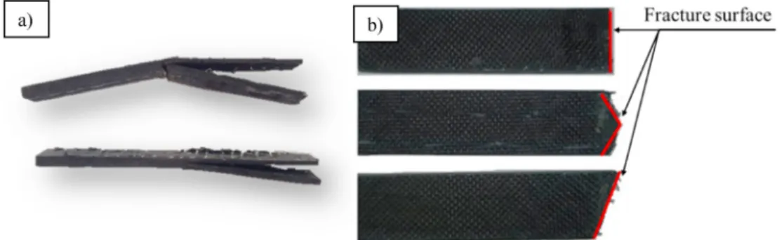
In both patterns, only a partial fracture appeared after 87.5% filling.
Furthermore, the tests showed that above 50% filling, there was no complete fracture. The common form of failure was delamination (Fig. 12 a). The fracture surface was evidently smoother in the reference samples. In modified samples, the fracture surface was not created in impacting direction of the hammer. In specimens with a diagonal pattern and also with the biaxial pattern, the fracture surface formed in the same direction as the pattern (Fig. 12 b), forming a larger fracture surface.
Maximum stress during the impact significantly decreased (Fig. 13) for both patterns with increased surface fill (with 95% probability and n
=45◦of freedom). The degree of adhesion significantly decreased with increasing amounts of PCL, as was confirmed in the previous micro- droplet test [22]. Due to a weaker connection, the load transfer between the matrix and the reinforcement was weakened. This behaviour is consistent with the results of previous tests. The results of dynamic and three-point bending tests are also consistent in this respect; after 62.5%
filling, stress significantly decreased.
Specific absorbed energy (Fig. 14), unlike in three-point bending, did not decrease after initial growth. An almost continuous increase can be observed. The difference is due to the different load modes. In the case of static three-point bending, the properties of the interface are more
dominant due to the slower, quasi-static loading, but in the dynamic tests, the energy absorbed is not significantly reduced, owing to the impact resistance of the PCL. The area under the curves increases essentially because of the more extended deformation section, and because the stress has not significantly decreased (see Fig. 15).
Increasing the surface fill also increased ductility (Fig. 14). There is a significant (70% at 100% filling) improvement, compared to the initial brittle behaviour. For dynamic tests, we found a final limit of the DI at 0.75 DI, which also appeared in the bending tests. The maximum ductility index was determined by the concentration of the interlayer.
5. Conclusions
A combined method—the simultaneous application of an interlayer and adhesion modification and its effect on pseudo-ductile behaviour was investigated in this paper. A local adhesion modifier was applied to the surface of the stitch-bonded unidirectional carbon fabric by FFF printing. As a result, the properties of the interlayer and crack propa- gation between the fibre and the matrix changed. To determine the change in interlayer properties, ENF tests were performed.
Fig. 13.Specimens after the impact; a) delaminated damage; b) formed fracture surface.
Fig. 14.Charpy-impact test stress values at different PCL contents.
Fig. 15.Charpy impact test results at different surface filling contents (●-SAE; ▴-DI).
•The ductility increased after the first stress peak was reached. The GIIc values belonging to the first stress peak also increased, but due to further deformation, a second peak also appeared in the modified samples, but not in the reference samples.
•The test results show that interlayer properties changed without a decrease in shear strength, and failure was gradual. As a result, en- ergy absorption capacity increased.
We also performed quasi-static and dynamic tests to further monitor ductile behaviour.
•We observed a similar behavioural change in both flexural and impact studies. Ductility increased with the concentration of the adhesion modifier, but at higher PCL concentrations, the composite was significantly softened.
•At lower additive contents (12.5%–50%), strength did not decrease significantly, but ductility improved.
The presence of the thermoplastic additive made it possible to repair damaged specimens.
•The damaged specimens were pressed at temperatures above Tg, and the PCL filled in the inhomogeneities caused by the first bending test.
•Up to 50% of the original modulus was recovered, which opens up new areas of application for the technology.
The results show that the energy required for crack propagation is significantly increased when PCL is used. Furthermore, in addition to the increased energy requirement, gradual damage appeared in the modi- fied specimens, increasing reliability. This behaviour allows the continued use of carbon fibre composites in areas where overloading occurs; the structure retains its structural integrity without causing immediate failure. The use of thermoplastics also allows for repair under appropriate parameters (temperature, pressure). The repairability al- lows an option for further use (after certain damages) that can provide a solution until a deeper repair or even replacement of the component (albeit the mechanical properties were below the original values) can be carried out.
Author statement for manuscript CSTE-D-21-00822
Bal´azs Magyar – Investigation, Methodology, Writing - original draft.
Prof. Tibor Czig´any – Conceptualization, Methodology, Funding acquisition, Supervision, Writing - review & editing.
Dr. G´abor Szeb´enyi – Investigation, Conceptualization, Methodol- ogy, Funding acquisition, Project administration , Supervision, Writing - original draft.
Declaration of competing interest
The authors declare that they have no known competing financial interests or personal relationships that could have appeared to influence the work reported in this paper.
Acknowledgements
We would like to sincerely thank the late Prof. Dr. h.c. mult. Jozsef ´ Karger-Kocsis for his support and valuable comments, which serve as a solid foundation of our research. The research reported in this paper and carried out at BME has been supported by the NRDI Fund (TKP2020 IES, Grant No. BME-IE-NAT) based on the charter of bolster issued by the NRDI Office under the auspices of the Ministry for Innovation and Technology. The research has also been supported by the NRDI Office
(NKFIH FK 124352 and NVKP_16-1-2016-0046).
References
[1] J. George, D. Bhattacharyya, Biocarbon reinforced polypropylene composite: an investigation of mechanical and filler behavior through advanced dynamic atomic force microscopy and X-ray micro CT, Express Polym. Lett. 15 (2021) 224–235.
[2] A. Khan, D. Dragatogiannis, P. Jagdale, M. Rovere, C. Rosso, A. Tagliaferro, et al., Novel carbon fibres synthesis, plasma functionalization, and application to polymer composites, Express Polym. Lett. 15 (2021) 361–374.
[3] D. Sethy, S. Makireddi, F.V. Varghese, K. Balasubramaniam, Piezoresistive behaviour of graphene nanoplatelet (GNP)/PMMA spray coated sensors on a polymer matrix composite beam, Express Polym. Lett. 13 (2019) 1018–1025.
[4] L. Tak´acs, F. Szabo, Experimental and numerical failure analysis of adhesive joint ´ of glass fiber reinforced polymer composite, Period. Polytech. - Mech. Eng. 64 (2020) 88–95.
[5] P.F. Liu, J.K. Chu, Y.L. Liu, J.Y. Zheng, A study on the failure mechanisms of carbon fiber/epoxy composite laminates using acoustic emission, Mater. Des. 37 (2012) 228–235.
[6] S.B. Sapozhnikov, Y. Swolfs, S.V. Lomov, Pseudo-ductile unidirectional high modulus/high strength carbon fibre hybrids using conventional ply thickness prepregs, Compos. B Eng. 198 (2020) 108213.
[7] C.E. Bakis, A. Nanni, J.A. Terosky, S.W. Koehler, Self-monitoring, pseudo-ductile, hybrid FRP reinforcement rods for concrete applications, Compos. Sci. Technol. 61 (2001) 815–823.
[8] J.M. Finley, H. Yu, M.L. Longana, S. Pimenta, M.S.P. Shaffer, K.D. Potter, Exploring the pseudo-ductility of aligned hybrid discontinuous composites using controlled fibre-type arrangements, Compos. Appl. Sci. Manuf. 107 (2018) 592–606.
[9] H. Yu, M.L. Longana, M. Jalalvand, M.R. Wisnom, K.D. Potter, Hierarchical pseudo- ductile hybrid composites combining continuous and highly aligned discontinuous fibres, Compos. Appl. Sci. Manuf. 105 (2018) 40–56.
[10] M. Arai, Y. Noro, K-i Sugimoto, M. Endo, Mode I and mode II interlaminar fracture toughness of CFRP laminates toughened by carbon nanofiber interlayer, Compos.
Sci. Technol. 68 (2008) 516–525.
[11] C.H. Wang, K. Sidhu, T. Yang, J. Zhang, R. Shanks, Interlayer self-healing and toughening of carbon fibre/epoxy composites using copolymer films, Compos.
Appl. Sci. Manuf. 43 (2012) 512–518.
[12] K. Pingkarawat, C.H. Wang, R.J. Varley, A.P. Mouritz, Mechanical properties of mendable composites containing self-healing thermoplastic agents, Compos. Appl.
Sci. Manuf. 65 (2014) 10–18.
[13] H. Mei, S. Zhang, H. Chen, H. Zhou, X. Zhai, L. Cheng, Interfacial modification and enhancement of toughening mechanisms in epoxy composites with CNTs grafted on carbon fibers, Compos. Sci. Technol. 134 (2016) 89–95.
[14] V. Kostopoulos, Mode II fracture toughening and healing of composites using supramolecular polymer interlayers, Express Polym. Lett. 10 (2016) 914–926.
[15] B. Yuan, M. Ye, Y. Hu, F. Cheng, X. Hu, Flexure and flexure-after-impact properties of carbon fibre composites interleaved with ultra-thin non-woven aramid fibre veils, Compos. Appl. Sci. Manuf. 131 (2020) 105813.
[16] B. Liu, N. Gao, S. Cao, F. Ye, Y. Liu, Y. Zhang, et al., Interlaminar toughening of unidirectional CFRP with multilayers graphene and MWCNTs for Mode II fracture, Compos. Struct. 236 (2020) 111888.
[17] A. Gatti, J.V. Mullin, J.M. Berry, in: S. Yurenka (Ed.), The Role of Bond Strength in the Fracture of Advanced Filament Reinforced Composites, ASTM International, West Conshohocken, PA, 1969, pp. 573–582.
[18] J.V. Mullin, V.F. Mazzio, The effects of matrix and interface modification on local fractures of carbon fibers in epoxy, J. Mech. Phys. Solid. 20 (1972) 391–394.
[19] A.G. Atkins, Imparting strength and toughness to brittle composites, Nature 252 (1974) 116–118.
[20] A.G. Atkins, Intermittent bonding for high toughness/high strength composites, J. Mater. Sci. 10 (1975) 819–832.
[21] T.U. Marston, A.G. Atkins, D.K. Felbeck, Interfacial fracture energy and the toughness of composites, J. Mater. Sci. 9 (1974) 447–455.
[22] G. Szeb´enyi, B. Magyar, T. Czigany, Achieving pseudo-ductile behavior of carbon fiber reinforced polymer composites via interfacial engineering, Adv. Eng. Mater.
23 (2021) 2000822.
[23] J. Yang, Q. Zhou, K. Shen, N. Song, L. Ni, Controlling nanodomain morphology of epoxy thermosets templated by poly(caprolactone)-block-poly(dimethylsiloxane)- block-poly(caprolactone) ABA triblock copolymer, RSC Adv. 8 (2018) 3705–3715.
[24] S.K. Siddhamalli, Toughening of epoxy/polycaprolactone composites via reaction induced phase separation, Polym. Compos. 21 (2000) 846–855.
[25] G. Szeb´enyi, T. Czig´any, B. Magyar, J. Karger-Kocsis, 3D printing-assisted interphase engineering of polymer composites, Concept Feasib. 11 (2017) 525–530.
[26] M.A. Azmah Hanim, D. Brabazon, M.S.J. Hashmi, Cracks, microcracks, and fracture toughness of polymer composites, in: M. Jawaid, M. Thariq, N. Saba (Eds.), Failure Analysis in Biocomposites, Fibre-Reinforced Composites and Hybrid Composites, Woodhead Publishing, 2019, pp. 157–180.
[27] J. Karger-Kocsis, Instrumented impact fracture and related failure behavior in short- and long-glass-fiber-reinforced polypropylene, Compos. Sci. Technol. 48 (1993) 273–283.