In-Network Velocity Control of Industrial Robot Arms
Sándor Laki
1, Csaba Györgyi
1, József Pet˝o
2, Péter Vörös
1, and Géza Szabó
31
ELTE Eötvös Loránd University, Budapest, Hungary
2
Budapest University of Technology and Economics, Budapest, Hungary
3
Ericsson Research, Budapest, Hungary
Abstract
In-network computing has emerged as a new computational paradigm made possible with the advent of programmable data planes. The benefits of moving computations tradition- ally performed by servers to the network have recently been demonstrated through different applications. In this paper, we argue that programmable data planes could be a key tech- nology enabler of cloud and edge-cloud robotics, and in gen- eral could revitalize industrial networking. We propose an in-network approach for real-time robot control that sepa- rates delay sensitive tasks from high-level control processes.
The proposed system offloads real-time velocity control of robot arms to P4-enabled programmable data planes and only keeps the high-level control and planning at the industrial con- troller. This separation allows the deployment of industrial control in non-real-time environments like virtual machines and service containers running in a remote cloud or an edge- computing infrastructure. In addition, we also demonstrate that our method can smoothly control 100s of robot arms with a single P4-switch, enables fast reroute between trajectories, solves the precise synchronization of multiple robots by de- sign and supports the plug-and-play deployment of new robot devices in the industrial system, reducing both operational and management costs.
1 Introduction
In the recent decade, there has been an increasing demand from customers towards the manufacturing industry to pro- vide more and more customized products. Personalized pro- duction is one of the key motivations for manufacturers to start leveraging new technologies that enable to increase, for instance, the flexibility of production lines. High flexibility, in general, is needed to realize cost-effective and customized production by supporting fast reconfiguration of production lines, as well as, easy application development. Fast recon- figuration and agile behavior can be achieved by moving the
Source code is available athttps://github.com/slaki/nsdi22.
robot control from the pre-programmed local robot controllers to the cloud. In industrial robotics research, cloud robotics is a major topic and in the last years, several studies [9,11,13]
have shown the benefits of connecting robots to a centralized processing entity: a) usage of more powerful computing re- sources in a centralized cloud especially for solving Machine Learning (ML) tasks; b) lower cost per robot as functionalities are moved to a central cloud; c) easy integration of external sensor data and easier collaboration or interaction with other robots and machinery; e) reliability of functions can be im- proved by running multiple instances as a hot standby in the cloud and the operation can immediately be taken over from faulty primary function without interruption.
Though centralized processing has clear benefits in making the management of industrial processes simple and flexible, cloud-based solutions cannot satisfy the low latency and high reliability network requirements of real-time industrial con- trol (e.g., velocity or torque control of actuators, robot arms, conveyor belts, etc.). Industry 4.0 and 5G propose the use of edge computing infrastructure for this purpose, moving these tasks to the computing nodes located close to the industrial environment. Though the propagation delay can significantly be reduced with this setup, edge-computing nodes rely on the same virtualization technologies as remote cloud infrastruc- tures. Existing solutions require real-time operating systems to eliminate the effects of CPU scheduling and ensure precise timing (e.g., in velocity control the velocity vectors need to be sent to the robot arms with accurate timing). Newer robot arms have 2 ms or less update time. The real-time velocity control of hundreds of such robot arms requires an ultra-fast response time that is hard to satisfy with traditional edge computing infrastructure.
With the advent of PISA switches [3] and the P4 lan- guage [2], a new era has begun in which programmable net- work devices can not only perform pure packet forwarding but simple computations as well. This trend led to the birth of a new computational paradigm called in-network computing, where server-based computations or a part of them are moved to programmable data planes. This new way of using network-
ing hardware can open up the fields for low-latency real-time calculations on the application level during the communica- tion. Foremost, they can split long, distant control loops into smaller ones to deal with transport latency, enable computa- tions at line rate and ensure real-time response time in orders of microseconds, solving the previously described problems of cloud and edge-cloud robotics.
In this paper, we investigate how cloud robotics can benefit from the advances of in-network computing. In particular, we propose a system in which high-level control of indus- trial processes can be deployed in the cloud (or edge cloud) while low-level speed control of the robot arms is offloaded to the programmable data plane (switch, smart NIC, or service card). Similarly to recent practical deployment options [6], we only assume reliable network connections with low la- tency between industrial robots and the programmable data plane. This design has the advantage that the high-level in- dustrial controller does not require real-time OS and has less strict end-to-end delay requirements. Our vision is that P4- programmable data planes (e.g., smart NICs, service cards, switches) could complement the computational capabilities of cloud and edge cloud infrastructures for use cases where real-time operation, ultra-fast response time, high throughput, or all of these are required. Though the proposed method controls robot arms independently, we also demonstrate that it can easily synchronize the low level control processes of multiple robots and thus can potentially provide support for coordinated operation.
Moving low-level robot control to the network poses many challenges that are addressed in this paper: 1) How can veloc- ity control be implemented with the limited instruction-set of programmable hardware data planes? 2) What is an efficient trajectory representation? 3) What to do if the entire trajec- tory does not fit into the memory? 4) How can match-action tables be used as playback buffers of trajectories? 5) How can trajectory segments be loaded in the limited memory of the switch and updated without violating timing requirements?
6) What constraints are needed for the data and control plane interactions? 7) How can the low-level control of multiple robot arms be synchronized? 8) How can switching to an al- ternative trajectory be solved in run-time (e.g., implementing a collision avoidance or emergency stop operations)?
2 Related Work
The related work of this paper covers a wide area of expertise from various research fields. We grouped them according to the different topics.
Traditional characteristics of robots.An industrial robot has many metrics and measurable characteristics, which will have a direct impact on the effectiveness of a robot during the execution of its tasks. The main measurable characteristics are repeatability and accuracy. In a nutshell, the repeatability of a robot might be defined as its ability to achieve repetition
of the same task. While, accuracy is the difference (i.e., the error) between the requested task and the realized task (i.e., the task actually achieved by the robot). For more details about the calculation of accuracy and repeatability, see [10].
The ultimate objective is to have both; a robot that can re- peat its actions while hitting the target every time. When the current mass production assembly lines are designed, robots are deployed to repeat a limited set of tasks as accurately and as fast as possible to maximize productivity and minimize the number of faulty parts. The reprogramming of the robots rarely occurs, e.g., per week, per month basis and it takes a long time, e.g., days, requiring a lot of expertise.
Network aspectsAuthors of [7] compare the network pro- tocols used nowadays in industry applications e.g., Modbus, Profinet, Ethercat. All investigated Industrial Ethernet (IE) systems show similar basic principles, which are solely im- plemented in different ways. Several solutions apply a shared memory and most systems require a master or a compara- ble management system, which controls the communication or has to be configured manually. Shared memory is imple- mented via data distribution mechanisms that are based on high frequency packet sending patterns. These packets have to be transmitted with strict delivery time and small jitter.
IE protocols rely so heavily on the transport network that protocol mechanisms common in broadband usage like re- liable transmission, error detection, etc. are not among the basic features of industrial protocols. Authors of [1] sum- marize the fundamental trade-offs in 5G considering various dimensions of block-lengths, spectral efficiency, latency, en- ergy consumption, reliability, etc. Numerous aspects have to be solved during an industry automation task even when the robot stands still.
In-Network Industrial ControlIn-network control is a way to offload critical control tasks into network elements man- aged and organized through a remote environment. In the past few years, numerous papers offered solutions for In-Network Complex Event Processing (CEP). These works focus on sensor data-driven event triggering based on specific thresh- old values. Authors of [15] demonstrate such a system for a strongly delay-sensitive use case, controlling an inverted pendulum. By outsourcing the control to a distant controller, they show how a very low RTT of 5-20ms can break the entire system or make it oscillate badly. By combining in-network processing with the distant controller, they were able to utilize the ultra-low latency of local communication, and the control of the pendulum showed identical results as with fully local control. This paper mainly focuses on the implementation of the LQR controller in P4 and the limitations of the P4 language. Though the method we propose in this paper also uses a controller (PID-like) in the middle of the pipeline, it goes much further by providing an abstract representation of function components with error bounds that can poten- tially be used in any controller algorithms. In addition, our approach also handles many other problems: trajectory-based
control, switching between trajectories, synchronization of multiple robots, etc. In [12] authors demonstrate their own P4-based CEP rule specification language. P4CEP’s system model works with a collection of end-systems that are inter- connected by programmable network processing elements.
End-systems are differentiated into event sources, and event sinks where the sinks can react to certain conditions observed by the event sources. FastReact [20] is another In-Network CEP system that advocates the idea to outsource parts of an industrial controller logic to the data plane by making the pro- grammable switches able to cache the history of sensor values in custom data structures, and trigger local control actions from the data plane. [4] shows a robot control system where a P4 switch is located between an emulated robot arm and the controller. The switch can analyze both sides of the traffic. If it detects that a position threshold is violated by the robot, it sends back an emergency stop message within a very short time due to the local communication. This work only covers this simple failure detection scenario and cannot deal with the more advanced control of robot arms we show in this paper.
3 System Design
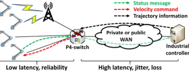
The main goal of this paper is to demonstrate the feasibil- ity and practical benefits of programmable data planes in low-level industrial control. To this end, we show how real- time velocity control of robot arms can be implemented in P4-programmable network devices and how they can be inte- grated into the existing industrial ecosystem. Fig.1depicts the high-level architecture of the proposed system, enclos- ing one or more robot arms, a P4-switch, and an industrial controller. It is important to note that this is a practical deploy- ment option. The first phase of the introduction of wireless communication into production cells looks similar [6].
Robot arms.We assume simple robot arms without in-built intelligence. Each robot arm consists of a number of joints controlled by actuators (i.e., servo motors). The actuators work independently, stream their internal state (position and velocity) at a constant frequency (generally in the range of 100Hz-1kHz) and require velocity control messages at a pre- defined rate (generally 100Hz-500Hz) to keep the movement smooth. Note that lost command messages may cause lags in the movement or deviance from the desired path to be fol- lowed. In our system model, each robot arm is handled as a set of actuators controlled in sync. However, many complex industrial processes also require the synchronized operation of multiple robots (or other devices like conveyor belts, etc.).
In the proposed system, this case can naturally be deduced to the single robot case by handling the cooperative robots as a single entity with all the actuators of the participating individual robots.
P4-switch.A programmable packet processing device sup- porting the P4 language [2] (e.g., PISA switch, smartNIC, or distributed service card) that processes the status streams of
Private or public WAN
Industrial controller P4-switch
Trajectory information Status message Velocity command
Low latency, reliability High latency, jitter, loss
Figure 1: System overview.
the robot joints and generate the velocity control commands from the state messages and the desired trajectory provided by the industrial controller. We assume a highly reliable network connection with suitably small propagation delay (depending on the robot’s control frequency) between the P4-switch and the robots.
Industrial controller.It is responsible for coordinating the industrial processes at a high-level and thus planning the trajectories to be followed by the robot arms, re-planning tra- jectories if needed (e.g., for collision avoidance), verification of the process, failure detection and response, and synchroniz- ing high-level processes. In our system design, the controller could be deployed at remote or edge cloud infrastructure. In the case of remote cloud deployment, the delay between the switch and the industrial controller could be in the order of 10-100ms with significant jitter. In both cases, the high-level industrial controller does not require real-time OS and thus can operate in a VM. Note that the industrial controller also gets the status information of the robots needed for tracking the whole industrial process, but cannot directly send com- mands to the actuators. Instead, it fills the match-action tables of the switch with a sequence of trajectory points needed for the P4-switch for controlling the robots at a low-level.
During operation, each robot arm executes the trajectory planned by the industrial controller. A trajectory is repre- sented by a sequence of trajectory points (TPs), where each TP has a unique identifier and is associated with a relative timestamp (starting with 0) and the expected state (joint ve- locities and positions) of the robot arm at the given point of the operational timeline. Two consecutive TPs may be far from each other in both time and joint spaces. In the proposed method, the P4-programmable switch is responsible for the transition between the two TPs by continuously updating the joint velocities of the robot arm.
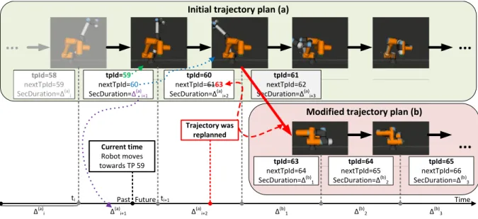
A trajectory example is depicted in Fig.2. The initial trajec- tory plan on the top is a sequence of snapshots describing the robot states at discrete points of time. In the snapshot images, the orange arm illustrates the final configuration to be reached and the other denotes the desired state in the given TP. A robot state is described by two vectors representing the desired joint velocities and joint positions. Note that though the robot arm moves in the Cartesian space (as shown in the figure), the in- dustrial controller maps the trajectory to the joint space (with
Initial trajectory plan (a)
... ...
...
tpId=58 nextTpId=59 SecDuration=Δ(a)i
tpId=59 nextTpId=60 SecDuration=Δ(a)i+1
tpId=60 nextTpId=6163 SecDuration=Δ(a)i+2
Trajectory was replanned Current time
Robot moves towards TP 59
Past Future
tpId=63 nextTpId=64 SecDuration=Δ(b)1
tpId=64 nextTpId=65 SecDuration=Δ(b)2
tpId=65 nextTpId=66 SecDuration=Δ(b)3
Δ(a)i Δ(a)i+1 Δ(a)i+2 Δ(b)1 Δ(b)2 Δ(b)3
tpId=61 nextTpId=62 SecDuration=Δ(a)i+3
Modified trajectory plan (b)
ti ti+1 Time
Figure 2: Trajectory example with re-planning.
units ofrad/sandrad). One can also see that the transition from one TP to another needs to be performed in the allocated section duration of∆j. In the figure, the robot is heading TP 59. The new joint velocities to be set are calculated from the current state of the robot arm and the desired state in TP 59.
Older TPs (e.g., 58 in the figure) have become obsolete. As soon as the target TP is reached, we switch to the next TP (60 in the example), heading the new associated robot state and also considering∆(a)i+2dedicated for the transition (from TP 59 to 60).
3.1 System Requirements
In this section, we identify the minimal set of requirements needed for low-level real-time control of robot arms in most industrial use cases. We need to consider them during the implementation of the proposed system.
Velocity-control requirement.The smallest building blocks to be controlled are the actuators in our system. Actuators can be controlled independently. Each of them periodically generates status messages carrying the current joint velocity (rad/s) and joint position (rad) values. These messages first need to be parsed by the P4-switch responsible for low level control. Then, the switch has to calculate the new velocity value by applying feed-forward control (e.g., PID) that com- bines the state, timing, and trajectory information. Finally, the result shall be written into a command message and sent back to the actuator. Actuators are using different state reporting and command execution frequencies (generally the former is higher). Actuators operate at a given frequency. Each actuator first waits for a command message in a time window of con- stant length. If the time window is over, the actuator executes the command. If multiple commands are received in a time
window, only the latest is kept and all the others are dropped.
Timing requirement. The precise timing of control com- mands is crucial since the actuators of the robot arms expect incoming commands with a given frequency and do not toler- ate large timeouts and jitter. In case of bursty arrival, a part of the commands may not be executed, leading to unexpected deviations from the desired trajectory. For example, an UR5e robot arm expects commands at 125 Hz, requiring a command message every 8ms. In addition, there are timing requirements between the P4-switch and the industrial controller on loading trajectory information. This requirement especially important if the entire trajectory cannot be stored in the switch (or it is not intended), and the controller periodically loads new TPs and deletes obsolete ones.
Synchronization requirement.Though we assume that ac- tuators can be controlled separately, they are not independent.
They belong to a single physical structure with its own kine- matics. Thus, the actuators of a single robot need to be coupled in the control process. In addition, most industrial processes require the cooperation of multiple robot arms. Synchroniza- tion requirements can be defined on different time-scales. For example, if a robot stops in a position and then another pro- cess is started, but there is no strict time constraint (e.g., few seconds are acceptable) between the two processes, a remote industrial controller can even solve the synchronization. How- ever, in several cases, this light synchronization is not enough, and thus the low-level control processes also need to work in sync (on a millisecond or sub-millisecond scale).
Trajectory switching requirement.The industrial controller continuously monitors the whole industrial process, and in- tervenes if needed (e.g., in case of failure or simple recon- figuration, or for collision avoidance purposes). This case is illustrated by Fig.2where the trajectory is modified (the red
point on the timeline), resulting in that after TP 60 the robot moves towards TP 63 instead of 61. Trajectory switching is needed when a robot is reconfigured or when an obstacle ap- pears in the robot cell and collision avoidance can be ensured by the new trajectory.
Communication requirement.To reduce packet processing overhead in the P4-switch, we assume that robot arms apply a datagram-based communication protocol (e.g., native Ether- net frames, UDP packets, etc.) for sending status information and receiving commands. Both status and command messages consist of simple decimal fields in a binary format that can be parsed by the P4-switch with ease.
4 Robot Arm & Network Protocol
The robot arm used in our experiments is an UR5e [17]. UR5e is a lightweight, adaptable collaborative industrial robot with six joints (6-DOF). It is commonly used in research as it has a programmable interface, can be remotely controlled, provides industrial grade precision, and can operate alongside humans with no safeguarding. The robot vendor also provides a real- time emulation environment (URSim) that is fully compliant with the real robot arms and thus can be used for testing validation purposes.
UR5e can receive external commands described in UrScript [19] language via its network interface. It communicates with external controllers over TCP by default. However, the net- work protocol can be customized by adding a URCap [18]
plugin (called daemon) to the robot. To make the commu- nication simple and stateless, we created a URCap daemon implementing the translation between the original TCP-based and our UDP-based protocols.
During the protocol design we considered two practical aspects: 1) P4 capable devices are not suited for deep packet inspection, and thus cannot parse the entire content of large packets. It implies that every important field used for robot control has to be close enough to the beginning of the packet.
2) Both status and command messages of the original commu- nication interface rely on floating point fields. However, the P4 language does not support floating-point arithmetic. This problem can be handled by multiplying each floating-point value with a properly large constant and then using the stan- dard decimal operations. Though it is possible to implement this conversion in P4, it is much simpler and comfortable if the value is already in a decimal format in the used protocol.
Considering the above aspects, we use the same header structure for status and command messages encapsulated into simple IP/UDP packets. The introduced robot header (rh) consists of four fields: 1) arobot ID(rh.RId) used as a unique identifier of the robot arm, 2)ajoint ID(rh.JointId) which determines the joint (or in general the actuator) of the given robot, 3) ajoint velocity(rh.velocity) expressing the current speed (inrad/s) of the given joint in the status messages or the new joint-speed value to be set in the commands, and 4) a
joint position(rh.position) which is the current position (in rad) of the given joint in the status messages, and unset in the commands.
5 Velocity Control in Data Plane
Though our prototype is implemented in P4-16 with the Tofino Native Architecture (TNA), we aim at keeping the data plane description in this section general. In our model, the switch consists of two packet processing pipelines: an ingress and an egress. The two parts have different roles and responsibilities in the proposed implementation:
• Ingress pipeline:This part is responsible for 1) deter- mining the current TP for the robot arm the status packet is sent by, 2) stepping the current TP to the next TP along the trajectory if required, or 3) switching to another tra- jectory in case of re-planning.
• Egress pipeline:This block solves the low-level veloc- ity control by calculating the new joint velocity value based on the available information (state packet and tra- jectory).
5.1 Ingress pipeline
We assume that each TP can be identified by a unique ID.
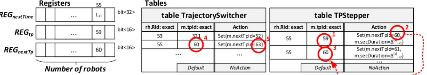
The memory layout of the ingress pipeline is depicted in Fig.3. One can observe that we maintain three registers for each robot to be controlled. They store the identifiers of the current (REGt p), the next (REGnextT p) TPs, and the absolute timestamp (REGnextTime) when the control has to step along the trajectory to the next TP. Fig.2provides a good illustration of the role of these three values. Accordingly, the robot moves towards the current TP (59) which should be reached atti+1 (REGnextTime) when we step forward to the next TP (60).
The ingress pipeline also contains two tables for storing the trajectory as a sequence of TPs and branching points where we can switch to another trajectory. TableTPStepperrepresents the trajectory to be followed by a robot arm as a linked list of TP identifiers. For each TPp, it stores the duration needed for moving from the previous TP topand the identifier of the next TP that followspalong the trajectory. One can observe that the next TP determines how the robot arm continues its operation after reachingp.
The current and next TPs usually belong to the same tra- jectory, but in some cases, re-planning is required. Table TrajectorySwitchersolves this problem by switching be- tween two trajectories. If there is a TPpalong the original trajectory which could also be the starting point of the new trajectory, the switch can be implemented by replacing the next TP ofpwith the appropriate TP along the new trajectory.
Thus after the branching pointp, the robot arm starts follow- ing the new trajectory also loaded into tableTPStepper.
Let us consider the example in Fig.3(see Fig.2for illus- tration). TableTPStepperis applied at timeti when TP 59 becomes the new TP (m.t pId=59) the robot arm is heading towards. At this point of time, the next TP is unknown and is filled from the table. The table also provides the section duration (m.secDuration=∆(a)i+1) allocated for reaching TP 59. This information is used for determining the absolute timestamp (ti+∆(a)i+1) when the current TP is replaced by the next one (TP 60) and then tableTPStepperis applied again.
Though it setsREGnextT pto 61 (next TP along the initial tra- jectory), tableTrajectorySwitcheroverwrites it with 63, the starting point of the new trajectory.
Algorithm1describes the ingress pipeline at a high ab- straction level. At arrival, the status message from a robot executes the program block starting with line 3. First, the trajectory state (T pId,nextT pId and thenextTime) is red from the registers.T pIddenotes the current TP the robot is currently heading towards andnextT pIdidentifies the next TP. Then tableTrajectorySwitcheris applied that replaces thenextT pIdif the current TP is a branching point. In most cases, there is no hit in this table. In line 6, we check if nextTimeis reached. If this condition is true, further actions (see line 11-16) are needed since we have to move to the next TP, update states (tableTPStepper) and write them into the registers. In high-performance hardware data planes like Barefoot Tofino, registers can only be accessed once during the pipeline to ensure line-rate performance even at the Tbps scale. This constraint can be resolved by resubmitting the packet (lines 8-9). In this case, the ingress pipeline is exe- cuted twice only. Though packet resubmission can reduce the overall throughput, in practice this step is only performed when the current TP is reached. Note that in software targets the proposed pipeline could be implemented without the need for resubmission, but in turn, we can expect higher latency and performance limitations.
The proposed implementation has further practical bene- fits. In case of repetitive tasks which is usual in industrial scenarios, we can simply create loops in tableTPStepper by setting the next TP to a TP visited previously. The syn- chronization of different robot arms can be solved either by merging the multiple robot arms into a single entity whose TPs represent the joint states of all participating robots or by creating a self-loop at the starting point of trajectories to be synchronized. In the latter case, if the section duration is long enough for inserting branching points to trajectories to be executed into tableTrajecotrySwitcher, the internal clock of the P4-switch ensures that robot arms start operating at the same time and are kept in sync during the industrial process.
5.2 Egress pipeline
The egress pipeline is responsible for calculating the velocity value to be set from the current state of the robot joint and the current TP (t pId). The new velocity value is computed
Algorithm 1:Ingress pipeline (pseudo-code) Robot header:rh,Metadata:m;
Registers:REGt p,REGnextT p,REGnextTime; Tables:TrajectorySwitcher, TPStepper;
apply block
1 ifrh.isValid()then
2 ifm.resubmitted==0then
3 m.tpId =REGt p(rh.RId);
4 m.nextTpId =REGnextT p(rh.RId);
5 m.nextTime =REGnextTime(rh.RId);
6 TrajectorySwitcher.apply();
7 ifm.nextTime>now()then
8 m.resubmit_needed= 1;
9 m.resubmit_data= m.nextTpId;
10 else
11 m.tpId = m.resubmit_data;
12 TPStepper.apply();
13 REGt p(rh.RId) = m.tpId;
14 REGnextT p(rh.RId) = m.nextTpId;
15 REGnextTime(rh.RId) += m.secDuration;
16 send_back();
17 else
18 Handling normal traffic (e.g., l2 forwarding);
by a simple PID-like controller, as the weighted sum of three values:
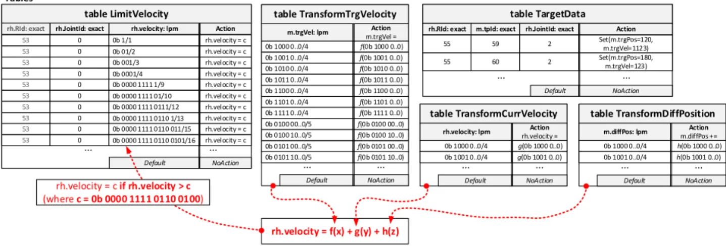
vnew=vcurr+c1(vtrg−vcurr) +c2(ptrg−pcurr), where cis are constants,vcurr and pcurr denote the current speed and position of the robot joint whilevtrgandptrgare the desired joint velocity and position in the current TP. One can observe that the new velocity can be composed of three linear transformations: (1−c1)vcurr,c1vtrg,c2pdi f f, where pdi f f =ptrg−pcurr. Each actuator may have different phys- ical properties and thus require differentciconstants in the transformations. The threeTransformtables in Fig.4are used for approximating these linear transformations.
The egress control block is described in Algorithm2. We first apply tableTargetDatato obtain the desired joint speed and joint position in the current TP (m.t pId). The actual state of the robot joint is carried by the robot header (rh). Lines 3-7 perform the primitive calculations needed for the P-controller mentioned previously. The new velocity is calculated as a sum of different components. Each component is calculated from metadata fields (diffPos stores the position difference) filled previously or from header fields by a transformation. The transformations are approximated by ternary or longest-prefix match (LPM) tables filled in run-time (see Sec.5.3). If the calculated velocity value is too large, it can cause damage to the robot arm. To take the physical limits of the robot joints into account we introduce the tableLimitVelocitychecking
ti+1
...
Registers REGne xtTime
... 59
... 60
REGtp
REGne xtTp
bit<32>
bit<16>
bit<16>
Number of robots
table TrajectorySwitcher
rh.RId: exact m.tpId: exact Action
53 321 Set(m.nextTpId=52)
Default NoAction
... ...
table TPStepper
rh.RId: exact m.tpId: exact Action
55 59 Set(m.nextTpId=60,
m.secDuration=Δ(a)i+1)
Default NoAction
... ...
Tables
55 60 Set(m.nextTpId=63)
55 60 Set(m.nextTpId=61,
m.secDuration=Δ(a)i+2)
... ...
1
2
4 5
3 55
Figure 3: Memory layout at ingress.
whether the calculated velocity value is outside of the safety range, and mapping it into the normal range if needed. The calculated joint speed is encoded into the velocity field of robot headerrhand sent back to the robot as a command message (lines 9-11).
Algorithm 2:Egress pipeline (pseudo-code) Robot header:rh,Metadata:m;
Registers:-;
Tables:TargetData, LimitVelocity,
TransformTrgVelocity, TransformCurrVelocity, TransformDiffPosition;
apply block
1 ifrh.isValid()then
2 TargetData.apply();
3 m.diffPos = m.trgPos - rh.position;
4 TransformTrgVelocity.apply();
5 TransformCurrVelocity.apply();
6 TransformDiffPosition.apply();
7 rh.velocity += m.trgVel + m.diffPos;
8 LimitVelocity.apply();
9 swap_ipAddresses();
10 swap_udpPorts();
11 clear_checksums();
12 else
13 Handling normal traffic;
5.3 Approximating transformations
The new velocity value is calculated by applying transfor- mations on some header or metadata fields. In our proof-of- concept P-controller, these transformations are simple multi- plications with predefined constants, but this design enables us to apply even non-linear mappings.
Such a transformation can be approximated by a Longest- Prefix-Match (LPM) or a ternary-match table as depicted in Fig.4. The match key is the parameter of the function (e.g., a header or metadata field), considering the most significant nbits starting with 1 (positive case) or 0 (negative case), as illustrated in Fig.5. The action parameter is the function value
calculated from the significant bits only. Since we only use simple weight functions in our implementation, the relative error of the approximated output equals the relative error of the input, more precisely the relative error of the estimation based on the most significantnbytes. The estimated value for the input can vary between the largest and smallest possible values with the given prefix. During this process, we skip the leading zeros (or ones in case of negative values) and ignore the lastkbits. Depending on this estimation, the relative error is less than or equal to 1/2n−1.
This approach fits well with the velocity control use case.
If the input is small – suggesting that we are close to the target TP, we need to make a more precise movement – the approximation has a small absolute error. If the input has a higher absolute value – meaning that we are far from the target value, and high precision control is not needed – the method provides an acceptable higher absolute error.
This method can be improved with a small trick. The num- ber of possible outputs is exactly the number of ternary en- tries. However, we can calculate the approximated value of (c−1)x instead of cx and add one more x to the re- sult in the P4 program. This technique applied in Table TransformDiffPositionhelped to improve the stability of the applied P-controller.
5.4 Limiting joint velocities
The different joints have their own physical properties that de- termine the maximum applicable velocity. To check the speed constraints and limit the velocity if needed, we apply table LimitVelocity. Letxbe the velocity value (rh.velocity) to be tested andcbe a constant value. Starting with the positive case, we can always decide whetherx>cifxhas the samen long prefix ascbutx[n+1] =1 andc[n+1] =0. Note that x[1]denotes the most significant bit ofx. The negative case is similar. Ifxhas the samenlong prefix ascbutx[n+1] =0 andc[n+1] =1 thenx<c. For an input ofkbits, we need at mostkentries in the table for each constant check. Fig.4 shows a small example with the necessary prefix checks, con- sidering a 16-bit long input value and predefined constant c. In the case of signed inputs, the first bit shall be handled carefully, but comparing to a negative number can be done similarly.
table TransformTrgVelocity
m.trgVel: lpm Action
m.trgVel = 0b 1000 0..0/4 f(0b 1000 0..0)
Default NoAction
... ...
table TargetData
rh.RId: exact m.tpId: exact Action
55 59 Set(m.trgPos=120,
m.trgVel=1123)
Default NoAction
... ...
rh.JointId: exact 2
Tables
table LimitVelocity
rh.RId: exact rh.JointId: exact Action
53 0 rh.velocity = c
Default NoAction
... ...
rh.velocity: lpm 0b 1/1
55 60 Set(m.trgPos=180,
m.trgVel=123) 2
53 0 0b 01/2 rh.velocity = c
0b 1001 0..0/4 f(0b 1001 0..0) 0b 1010 0..0/4 f(0b 1010 0..0) 0b 1011 0..0/4 f(0b 1011 0..0) 0b 1100 0..0/4 f(0b 1100 0..0) 0b 1101 0..0/4 f(0b 1101 0..0) 0b 1111 0..0/4 f(0b 1111 0..0) 0b 0100 00..0/5 f(0b 0100 00..0) 0b 0100 10..0/5 f(0b 0100 10..0) 0b 0101 00..0/5 f(0b 0101 00..0) 0b 0101 10..0/5 f(0b 0101 10..0)
table TransformCurrVelocity
rh.velocity: lpm Action rh.velocity = 0b 1000 0..0/4 g(0b 1000 0..0)
Default NoAction
... ...
0b 1001 0..0/4 g(0b 1001 0..0)
table TransformDiffPosition
m.diffPos: lpm Action
m.diffPos +=
0b 1000 0..0/4 h(0b 1000 0..0)
Default NoAction
... ...
0b 1001 0..0/4 h(0b 1001 0..0)
rh.velocity = f(x) + g(y) + h(z)
53 0 0b 001/3 rh.velocity = c
53 0 0b 0001/4 rh.velocity = c
53 0 0b 0000 1111 1/9 rh.velocity = c
53 0 0b 0000 1111 01/10 rh.velocity = c
53 0 0b 0000 1111 0111/12 rh.velocity = c
53 0 0b 0000 1111 0110 1/13 rh.velocity = c
53 0 0b 0000 1111 0110 011/15 rh.velocity = c
53 0 0b 0000 1111 0110 0101/16 rh.velocity = c
rh.velocity = c if rh.velocity > c (where c = 0b 0000 1111 0110 0100)
Figure 4: Memory layout at egress.
0 0 … ... 0 0 1 1 0 0 1 0 ? ? ? … …
128-n-k bit n bit k bit
Figure 5: Considering the most significant n bits starting with 1 (positive case).
6 ROS integration
In this section, we briefly introduce our industrial controller implementation based on the Robot Operating System (ROS) [14] and its MoveIt [5] library used for generating and execut- ing trajectories in a robot agnostic manner. ROS is an open- source robotics framework used in various robotics-related research since it can easily be extended and customized for specific use cases. Our ROS-based industrial controller uses MoveIt for motion planning and mobile manipulation of robots. In the proposed system, it generates aJointTrajec- torymessage containing an array of points (timestamps, 6 joint positions, 6 joint velocities), as UR5e has six joints (as shown in Fig.2).
The architecture of the industrial controller is shown in Fig.6. The components developed to support the proposed system are marked by gray. They have been integrated with the standard MoveIt architecture consisting of trajectory gen- eration using MoveIt planning, trajectory execution with MoveIt using standard ROS interface, and communication via the ROS driver of the UR5e arm.
To generate trajectories we can use RVIZ, a ROS visualizer software, with a MoveIt Motion Planning Plugin. Using RVIZ, we can generate trajectories interactively from a start point to a selected endpoint. Another way to generate trajectories is by 1) creating waypoints in Cartesian space, 2) then sending those points to a ROS node, 3) it computes a trajectory in joint space (defined by the joint angles of the robot) and 4)
ROS UR driver
RobotUR
Trajectory exporter
proxy
Switch control plane
MoveItt rajectory execution Alternative trajectory generation Trajectory generation
MoveIt trajectory planning Waypoints
RVIZ
ROS
Switch data plane
Figure 6: Trajectory generation and execution
finally it visits them in order.
The resulting joint trajectory is sent to MoveIt trajectory execution, which uses the ROS action interface defined by the UR driver to execute the trajectory on URSim/UR5e or it can also send the trajectory to the P4-switch’s control plane via the Trajectory Exporter proxy, which fills the appropriate tables and let the switch execute the trajectory instead of the ROS UR driver.
6.1 Alternate trajectory generation
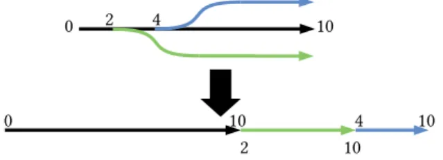
We developed Alternate trajectory generation to extend the existing capabilities of the system. Alternate trajectory gen- eration and execution is a feature that leverages the ability of the P4 system to quickly change chains of trajectories, to execute prepared alternate trajectories in response to external changes e.g., in the robot’s surroundings.
The alternate trajectory generation node uses MoveIt’s tra-
jectory planning to prepare multiple branching trajectory frag- ments, then concatenates them into a single trajectory. The alternate trajectories are placed after each other, therefore the timestamps of the whole branching trajectory are not strictly incremental. Fig.7shows this process, the numbers indicate the timestamps of the trajectory’s start and endpoints.
0 2 4 10
0 10
2 10
4 10
Figure 7: Generating a single trajectory from alternate ones As the timestamps do not strictly increase, we can not use the trajectory execution of MoveIt. MoveIt is not able to execute alternate trajectories. Therefore we send the encoded trajectory to a proxy ROS component (node) which forwards the trajectory to the P4-switch.
We are also able to generate alternate trajectories on the fly when a trajectory is already being executed. We achieve this by keeping track of what is the current time in the currently executed trajectory. As we know the current time, we know where the robot will be in a∆ttime. That point can be the start point of an alternate trajectory. To ensure a smooth transition during the switch between alternate trajectories we need to estimate the position of the switching as accurately as possible.
To do this we need to estimate the 1) the latency between the industrial controller and the switch (RT T), and 2) the expected trajectory generation time (tprocessing). For the estimation of the start position (pstart(t)) at time (t) we came up with the following formulae:
∆t=tprocessing+RT T ppredict(t) =ptra j(t+∆t)
+pstatus(t)−ptra j(t) + (vstatus(t)−vtra j(t))×∆t pstart(t) =bppredict(t)× 1
g(t)c ∗g(t)
Where the error is estimated on the trajectory calculation side by calculating the difference of the position of the joints re- ceived in the last status message and the executed trajectory position. This is further adjusted by the difference of the cur- rent velocity of the joints and trajectory velocity times∆t.
A binning of the values with an integer division and mul- tiplication with the original granularity (g(t)) is applied on the predicted position value to replicate the behavior of the ternary table on the trajectory planner side and consider the granularity of the number representation in the specific time.
g(t)can be derived from the maximum of relative error (Mrel, see Sec.5.3) byg(t) =l pm(ptra j(t),Mrel).
Fig.8shows an example on the error ofpstart(t)compared to pstatus(t+∆t), which is the joint position at the time of switching.
–:ptra j(t+∆t)
–:+pstatus(t)−ptra j(t)) –:+(vstatus(t)−vtra j(t))×∆t
Figure 8: An example on the error ofpstart(t)compared to the later joint state
7 Evaluation
We carried out several experiments analyzing whether the pro- posed implementation can hold the identified system require- ments. To this end, we deployed a simple testbed consisting of two servers (AMD Ryzen Threadripper 1900X 8C/16T 3.8 GHz, 128 GB RAM) and a Barefoot Tofino-based switch (STORDIS BF2556X-1T). One of the servers (called Server- A) is equipped with a dual port 10 Gbps NIC (Intel 82599ES) that supports hardware-based timestamping. This node is con- nected to the switch via two 10 Gbps links. The other server (Server-B) is equipped with a Mellanox ConnectX-5 dual port NIC whose ports are connected to the switch via two 100 Gbps links. For latency experiments, we used MoonGen tool [8] on Server-A with hardware-based timestamping to generate robot and mixed traffic. During the latency mea- surements, Server-B continuously generated non-robot back- ground traffic with IP/TCP packets of size 1280B. We aimed to demonstrate the case that some ports of the P4-switch are dedicated to handling robot traffic while others forward nor- mal traffic in parallel. For operational experiments, we used a real UR5e robot arm connected to the switch and Server-B was running one emulated UR5e [17] robot using the official URSim robot emulator. Note that the emulator provided by the robot vendor is fully realistic and works in real-time. Dur- ing the experiments, we did not realize notable differences between the emulated and the real robot arm. In this scenario, our ROS-based industrial controller was run on Server-A and communicated with the control plane of the switch, loading and removing trajectory points.
The performed evaluation scenarios were designed to as- sess the proposed system in various common robotic use cases: 1) Pick and place actions: See Sec.7.3, 2) Welding, painting, gluing: See Sec.7.4, 3) Robot to robot collaboration:
See Sec.7.2, 4) Heterogeneous sensor and actuator deploy- ment in the robot cell: See Sec.7.1, 5) Agile control, safety, robot to human collaboration: See Sec.7.5. The estimation
about scalability is covered by Appx.A.
7.1 Response time analysis and traffic load
A robot cell usually contains various sensor and actuator el- ements, meaning that there are other traffic sources in the robot cell than the one generated by the robot arm itself. The Supervisory Control And Data Acquisition (SCADA) sys- tems also generate considerate background traffic. This is why it is important to evaluate the proposed system on a het- erogeneous traffic mix. To this end, we carried out latency measurements under various traffic loads. In this scenario, MoonGen (Server-A) sent latency probes in every ms, mixed with various background traffic. The latency probes were valid robot status messages and thus they went through the entire robot control pipeline.
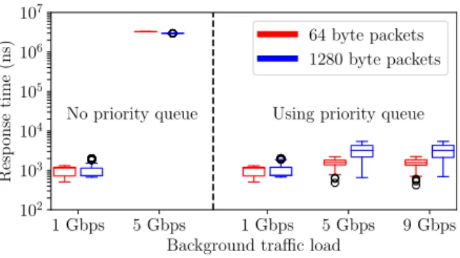
We evaluated the system with two different background traffic:1) Simple IP packets of 64B and 1280B sizeswere generated at variable sending rates (1-10 Gbps). The switch applied simple port forwarding and only the latency probes went through the robot-control pipeline. With small packet sizes the observed response time of robot traffic was in the range of [0.6µs, 1.3µs]. With packet size of 1280B the re- sponse time shifted towards 2µs as the load increased. This phenomenon was caused by one or more large background packets wedging between two latency probes. Note that at 10 Gbps transmitting a packet of size 1280B takes approx.
1µs. We also compared these measurements to the latency of a simple port forwarding program, the differences were not sig- nificant (<0.2µs).2) Robot status messageswere generated as background traffic, and thus all the packets went through the entire robot control pipeline. The latency results were basically identical with the previously described case of us- ing 64B IP packets. The response time was ranging between 0.6µs and 1.3µs.
Though these measurements only show the response time in under-loaded situations without queueing effect, they are represented in most industrial environments where a num- ber of assumptions can be made:1) predictable and stable loadsince the device settings determine the packet genera- tion frequencies; each device operates as a constant bit-rate source. The packet sizes are known and thus the overall load can easily be predicted. For example, a 6-DoF robot operat- ing at 500 Hz (e.g., UR5e sends status messages at this rate;
sending in every 2ms) generates approx. 1.5 Mbps status traf- fic on the upstream direction. Thus, the packet processing pipeline is required to ensure non-blocking operation at 3000 packets/s for a single robot. Considering 1000 robot arms which is far above the number of robots used in industrial setups nowadays, the required forwarding rate is 3M pack- ets/s (approx. 1.5 Gbps) on average. However, considering synchronized robots whose status messages are sent within a short time window, the bursty arrival at the P4-switch can lead to higher peak rates to be handled. For example, if status
messages from all the robots arrive within a time window of 1ms (50% of the 2ms sending interval), the observed temporal rate could be 3 Gbps or higher. One can observe that these arrival rates can easily be served by currently available P4- hardware including both smartNICs, DSCs, and P4-switches.
2) The robot-control traffic can be separatedfrom other traffic either by assigning dedicated ports and/or pipes to robot traffic or using simple priority queues giving higher priority to industrial traffic than background packets. Note that priority queueing is supported by most of the networking elements (also including non-P4-programmable ones). This scenario is examined in more detail in Appx.C.
We also tested our pipeline enforcing the packet resub- mission at ingress, but it had no visible effect on the latency distribution. Finally, we repeated all the delay measurements with generating robot traffic at 100 Gbps from Server-B, but it has no effect on the observed latency at Server-A.
7.2 Synchronization measurements
Robot to robot collaboration is an important use case in any industrial robot cell deployment. To speed up the assembly process a usual deployment contains a robot arm moving the part to be worked with into various reachable positions for the other arm that has various grippers and executes a specific assembling order. The two arms need perfect synchronization otherwise the resulting product is faulty.
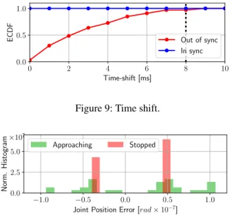
In this operational experiment, we launch the real UR5e robot arm and an instance of the URSim robot emulator, both are controlled by the switch and we start the trajectories in sync and out of sync. Fig.9shows the time shift between the start times of the two robots. The experiment was repeated 20 times. In the synchronized case, we created a single entity from the two robot arms with 2×6 joints and launched the trajectory by adding an entry to the TrajectorySwitcher table.
The result is a fully synchronized operation as depicted by blue in the figure. In the non-synchronized case, the two en- tries are inserted independently to start the two robots. Note that we observe an 8 ms time shift in the worst case that is comparable with the control frequency of the robots (125 Hz) and can simply be caused by the 8 ms real-time window of the robots. Though the observed time-shift is basically negligible for two robot arms, we assume that it may be much more significant if a larger number of robots is launched indepen- dently.
7.3 Accuracy at stop position
The accuracy and repeatability of a robotic arm are essential key performance indicators (KPIs) that need to be maintained even in a cyber-physical-system, i.e., remote control over the network. The basic pick and place, and palletizing use cases mostly depend on them. It is a bare minimum that the proposed system works well in these use cases.
0 2 4 6 8 10 Time-shift [ms]
0.0 0.5 1.0
ECDF Out of sync
In sync
Figure 9: Time shift.
−1.0 −0.5 0.0 0.5 1.0 Joint Position Error [rad×10−7]
0.0 2.5 5.0
Norm.Histogram
×107
Approaching Stopped
Figure 10: Joint position error at stop.
We performed experiments to analyze the accuracy of the control at the stop position (at the end of the trajectory) of the robot arm. One can observe in Fig.10that the error from the expected joint position was about 0.5×10⁻⁷radwhich was caused by the applied number representation (see Sec.5.3).
The green bars illustrate the deviance when the joint speed is not absolute zero, but the joint is close to its target position.
Note that 0.5×10⁻⁷raderror in the joint position corresponds to 0.5µm with a 1m long robot arm. In a robot arm with multiple joints, the cumulative position error is still in the order of micrometers.
7.4 Accuracy along the trajectory
The assembling quality and the endurance of a product mostly depend on the quality of gluing, welding and painting work.
To ensure this, the robot needs to be accurate not only in the goal positions but all along the planned trajectory.
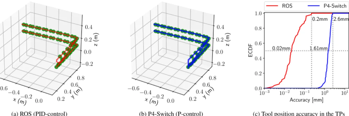
Though the proposed implementation is highly config- urable and supports the fine tuning of the applied P-controller, more advanced controllers (e.g., PID) can obviously provide more precise control. In this experiment, we measure the accu- racy of the robot head at the trajectory points and compare the results to the PID-based velocity control of ROS. Both ROS and the emulated robot run on the same server, representing ideal circumstances for ROS-based control.
Fig.11aand11bdepict the TPs (green points) as well as the path of the tool at the end of the robot arm (solid curves) for controls based on ROS and P4-Switch, resp. Both paths show a similar character. The accuracy of the two solutions is presented in Fig.11c. ROS’s fine-tuned PID-controller provides a 0.1 mm accuracy in the worst case which is 3.2
mm in the case of our proof-of-concept P-controller. The median accuracy values are 0.04 mm and 2.23 mm for ROS and P4-Switch, respectively.
7.5 Continuous table management
Industry 4.0 introduces the concept of agile robot cell control that requires fast reaction to external events, e.g., based on camera or force sensor feedback. Ensuring safety during robot and human collaboration is also critical. It is essential for the proposed system to react fast to external triggers.
In this experiment, we used the same measurement setup as in Sec.7.1. We generated robot traffic at 10 Gbps and sam- pled the latency every 1 ms. In the beginning, we loaded 3.4K trajectory points to the switch and then started the operation.
In every 1 second, we add 1.6K new TPs and remove 10K outdated TPs, illustrating the case when the switch is only used as a playback buffer, and the trajectory segments are loaded incrementally, while the old points are removed. Note that inserting a trajectory point with 6 joints requires the inser- tion of 12 entries into two exact-match tables. According to realistic scenarios, a trajectory normally contains 5-10 points in a second. Fig.12illustrates the latency samples and their moving average (on the bottom), and also shows the number of trajectory points (black) loaded into the switch in time, marking the insertion (blue) and removal (red) phases (on the top). One can observe that the insertion does not affect the packet processing latency in this scenario.
8 Discussion on Possible Deployment
Apart from the theoretic aspect and the successful proof study that the proposed system is feasible to deploy, the possibil- ity of a real industrial deployment is much dependent on the cost factors. A simple calculation reveals that a Tofino-based router costs approx. 9500 USD and it can serve up to 500- 1000 robots in parallel which means that the cost of control- ling a robot is less than 10-20 USD. It is less than applying mini PCs for hobby use, e.g., Raspberry Pis, and far less than certified industrial robot controllers or routers. The energy consumption of the proposed setup is expected to be much lower than the sum of industrial routers and robot controllers.
A network device has better transported traffic per watt ratio than a general purpose computation device that the current robot controllers contain. Though in industry, usually low per- formance, but reliable old CPUs are applied. According to [3]
a programmable switch will result in about 14% extra cost, compared to a non-programmable one, due to the larger area requirement for transistors. It is an interesting aspect if energy saving can be achieved by switching non-working elements on and off. One can observe that the capabilities of a Tofino are far more than what is required for the robot control use case. The utilization of the device can be improved by only
x (m)
−0.6
−0.4
−0.20.0 y(m) 0.2
0.4 0.6
0.8
z(m)
−0.2 0.0
0.2 0.4
(a) ROS (PID-control)
x (m)
−0.6
−0.4
−0.20.0 y(m) 0.2
0.4 0.6
0.8
z(m)
−0.2 0.0 0.2 0.4
(b) P4-Switch (P-control)
10−3 10−2 10−1 100 101 Accuracy [mm]
0.0 0.2 0.4 0.6 0.8 1.0
ECDF
2.6mm 0.2mm
0.02mm 1.61mm
ROS P4-Switch
(c) Tool position accuracy in the TPs
Figure 11: Path of the robot arm tool in the Cartesian-space and the observed accuracy in the TPs.
2500 5000 7500
#TPs
Add TPs Remove TPs
0 2000 4000 6000 8000 10000
Time [ms]
0 1000
Latency[ns]
Mean
Figure 12: Dynamic insertion and removal of trajectory points.
dedicating a part, e.g., a quarter of the switch to robot control while other parts can work on other tasks (e.g., routing).
The current workflow of a robot is that when it is switched on, it starts streaming out the internal status messages at a con- stant rate. Production cells are expected to operate 24 hours a day, so little can be done dynamically, apart from the fact that the default power consumption is significantly lower than current systems. The typical power consumption of a Tofino switch is around 110 W [16], while an average server requires 400-600 W. A modern server CPU alone can consume 165 W (Intel Xeon Gold 6348H Processor) at full load. If we com- pare the costs of purchasing a server with similar processing power and memory to the cheapest P4-Switch, the difference is not too significant. For a brief discussion on x86 alterna- tives see Appx.B. Also note that this is the first commercially available version of the Tofino switch, and as more and more new models appear and become more available, prices are expected to drop.
Considering the edge-cloud deployment scenario men- tioned in Sec.1, offloading computations that are simple but have real-time requirements that cannot be satisfied in a virtu- alized environment also have practical benefits. In this case,
distributed service cards or smart NICs with P4 programmabil- ity could be more cost effective solutions than a Tofino-based switch. They cost around 1500-3000 USD, also enables line rate (10-40 Gbps) processing with sub-millisecond response time, and have a typical power consumption of 20-50 W.
9 Conclusion
In this paper, we have introduced the first in-network control system that uses P4-programmable network devices for not just triggering events based on threshold values, but to do low-lever real-time velocity control for highly delay-sensitive robotic arms that can be used in industrial automation. With several experiments, we have proved that our system satis- fies the most crucial factors of industrial robot control. We measured the latency and observed that it meets the require- ments needed for real-time control even during the constant insertion and deletion of lookup table entries. We witnessed a maximum of an 8 ms time shift in the worst-case scenario between synchronous robots, making them fully capable of collaboration. We evaluated the end-position precision per joint to be under 0.5µm for a 1 m long robot arm, while the accuracy along the whole trajectory to be lower than 2.6 mm in the worst-case.
Acknowledgment
We thank the anonymous reviewers for their valuable feed- back on earlier versions of this paper. S. Laki and P. Vörös also thank the support of the "Application Domain Specific Highly Reliable IT Solutions" project that has been imple- mented with the support provided from the National Research, Development and Innovation Fund of Hungary, financed un- der the Thematic Excellence Programme TKP2020-NKA-06 (National Challenges Subprogramme) funding scheme.
References
[1] Mehdi Bennis, Mérouane Debbah, and H. Vincent Poor.
Ultra-Reliable and Low-Latency Wireless Communi- cation: Tail, Risk and Scale. CoRR, abs/1801.01270, 2018.
[2] Pat Bosshart, Dan Daly, Glen Gibb, Martin Izzard, Nick McKeown, Jennifer Rexford, Cole Schlesinger, Dan Talayco, Amin Vahdat, George Varghese, and David Walker. P4: Programming protocol-independent packet processors.SIGCOMM Comput. Commun. Rev., 44(3):87–95, July 2014.
[3] Pat Bosshart, Glen Gibb, Hun-Seok Kim, George Vargh- ese, Nick McKeown, Martin Izzard, Fernando Mujica, and Mark Horowitz. Forwarding metamorphosis: Fast programmable match-action processing in hardware for sdn. SIGCOMM Comput. Commun. Rev., 43(4):99–110, August 2013.
[4] Fabricio E Rodriguez Cesen, Levente Csikor, Carlos Recalde, Christian Esteve Rothenberg, and Gergely Pon- grácz. Towards low latency industrial robot control in programmable data planes. In2020 6th IEEE Confer- ence on Network Softwarization (NetSoft), pages 165–
169. IEEE, 2020.
[5] David Coleman, Ioan Alexandru Sucan, Sachin Chitta, and Nikolaus Correll. Reducing the barrier to entry of complex robotic software: a moveit! case study.ArXiv, abs/1404.3785, 2014.
[6] Comau 5G deployment.
https://www.ericsson.com/en/reports-and-
papers/ericsson-technology-review/articles/industrial- automation-enabled-by-robotics-machine-intelligence- and-5g, 2017.
[7] P. Danielis, J. Skodzik, V. Altmann, E. B. Schweissguth, F. Golatowski, D. Timmermann, and J. Schacht. Survey on real-time communication via ethernet in industrial automation environments. InProceedings of the 2014 IEEE Emerging Technology and Factory Automation (ETFA), pages 1–8, 2014.
[8] Paul Emmerich, Sebastian Gallenmüller, Daniel Raumer, Florian Wohlfart, and Georg Carle. Moongen: A script- able high-speed packet generator. InProceedings of the 2015 Internet Measurement Conference, IMC ’15, page 275–287, New York, NY, USA, 2015. Association for Computing Machinery.
[9] Y. Guo, X. Hu, B. Hu, J. Cheng, M. Zhou, and R. Y. K.
Kwok. Mobile cyber physical systems: Current chal- lenges and future networking applications.IEEE Access, 6:12360–12368, 2018.
[10] ISO: International Organization for Standardization.
1998. Manipulating industrial robots – Performance cri- teria and related test methods, NF EN ISO9283.https:
//www.iso.org/standard/22244.html, 1998.
[11] B. Kehoe, S. Patil, P. Abbeel, and K. Goldberg. A survey of research on cloud robotics and automation. IEEE Transactions on Automation Science and Engineering, 12(2):398–409, April 2015.
[12] Thomas Kohler, Ruben Mayer, Frank Dürr, Marius Maaß, Sukanya Bhowmik, and Kurt Rothermel. P4cep:
Towards in-network complex event processing. InPro- ceedings of the 2018 Morning Workshop on In-Network Computing, pages 33–38, 2018.
[13] D. W. McKee, S. J. Clement, J. Almutairi, and J. Xu.
Massive-scale automation in cyber-physical systems:
Vision amp;amp; challenges. In2017 IEEE 13th In- ternational Symposium on Autonomous Decentralized System (ISADS), pages 5–11, March 2017.
[14] Morgan Quigley, Brian Gerkey, Ken Conley, Josh Faust, Tully Foote, Jeremy Leibs, Eric Berger, Rob Wheeler, and Andrew Ng. Ros: an open-source robot operating system. InProc. of the IEEE Intl. Conf. on Robotics and Automation (ICRA) Workshop on Open Source Robotics, Kobe, Japan, May 2009.
[15] Jan Rüth, René Glebke, Klaus Wehrle, Vedad Cause- vic, and Sandra Hirche. Towards in-network industrial feedback control. InProceedings of the 2018 Morn- ing Workshop on In-Network Computing, pages 14–19, 2018.
[16] Nik Sultana, John Sonchack, Hans Giesen, Isaac Pe- disich, Zhaoyang Han, Nishanth Shyamkumar, Shivani Burad, André DeHon, and Boon Thau Loo. Flightplan:
Dataplane disaggregation and placement for p4 pro- grams. In18th USENIX Symposium on Networked Sys- tems Design and Implementation (NSDI 21). USENIX Association, April 2021.
[17] Universal Robot 5e. https://www.universal- robots.com/products/ur5-robot/, 2020.
[18] URCap. https://www.universal-robots.com/about- universal-robots/news-centre/launch-of-urcaps-the- new-platform-for-ur-accessories-and-peripherals/, 2014.
[19] URScript. https://www.universal-robots.com/how- tos-and-faqs/how-to/ur-how-tos/ethernet-socket- communication-via-urscript-15678/, 2017.
[20] Jonathan Vestin, Andreas Kassler, and Johan Åkerberg.
Fastreact: In-network control and caching for industrial control networks using programmable data planes. In