Modelling computer networks for further security research
Zsolt Bederna
1, Tamás Szádeczky
21 bederna.zsolt@stud.uni-obuda.hu
1 https://orcid.org/0000-0003-0444-7275
1 Doctoral School for Safety and Security Sciences, Obuda University, Bécsi út 96/B, 1034 Budapest, Hungary
2szadeczky@mail.muni.cz
2 https://orcid.org/0000-0001-7191-4924
2 Czech CyberCrime Centre of Excellence C4e, Masaryk University, Žerotínovo nám, 617/9, 601 77 Brno, Czech Republic
Abstract
Computer networks are usually modelled from one aspect, e.g., the physical layer of the network, although this does not allow the researcher to understand all usage of that device. We aim to develop a model which leverages all aspects of a networked computer and, therefore, provides complete information to the scientist for all further security research, especially that related to the social sciences.
Network science is about the analysis of any network, from social to protein. It is much easier to analyse computer networks with technical tools than protein networks. It is, therefore, a straightforward way to crawl the web as Albert-Laszlo Barabasi did to model its connections, nodes, and links in graph theory to analyse its internal connections. His analysis was based solely on the network layer.
Our methodology uses graph theory and network science and integrates all ISO/OSI (computer networking) layers into the model.
Each layer of the ISO/OSI model has its topology separately, but all of them also work as part of the complex system to operate the network. It therefore creates a multipartite graph of the network under analysis. Furthermore, the virtual private networks (VPNs) and application usage are also integrated as nodes and links. With this model, the computer network infrastructure and usage data can be used for further non-computing related research, e.g., social science research, as it includes the usage patterns of the network users.
Keywords:
graph, computer network, network science, network modelling
Article info Received: 23 July 2021 Revised: 12 August 2021 Accepted: 24 August 2021 Available online: 11 October 2021 DOI: http://doi.org/10.35467/sdq/141572
© 2021 Z. Bederna, T. Szádeczky published by War Studies University, Poland.
This article is an open access article distributed under the terms and conditions of the Creative Commons Attribution (CC BY) license (http://creativecommons.org/licenses/by/4.0/).
Introduction
I
n today’s world, the importance of cybersecurity and information security in public or- ganisations, businesses, governments, and individuals’ lives is continuously increasing for security games in the field of cyberspace. However, despite its importance, the status of the closed, complete, continuous, and risk-proportionate protection has generally not been reached either in cybersecurity or in information security. Although technology is important in both aspects of security, it is not the only factor (Pilarski, 2016). According to the information security perspective Business Model for Information Security (BMIS) model (von Roessing, 2010) created by ISACA in 2010, information security has four essential (static) elements as (1) Organisation, (2) People, (3) Process, and (4) Technol- ogy, which means that each organisation is considered a network of interacting people through processes while they apply the technology.For this case, technology includes every technical application used in the organisation, and it covers a broader set than traditional IT poses to be. However, the base of today’s technology is the Information and communications technology (ICT) which “encom- passes all technologies for the capture, storage, retrieval, processing, display, representation, or- ganisation, management, security, transfer, and interchange of data and information” (Inter- national Organisation for Standardization, 2013). So, modelling a network infrastructure is a must, as with the proper application in the planning and operation phase, a model is intended to help defend ICT.
In the operation phase, “network statistics have traditionally been used for managing the network layer and have driven tasks like network provisioning, routing, and fault detection”
(Stadler, Pasquini and Fodor, 2017, p. 673). Nevertheless, the right metrics, such as those based on network-level, local statistics for measuring services as applied in (Stadler, Pasqui- ni and Fodor, 2017), with the right model, may provide valuable information for real-time operation and even risk assessment and a different kind of wargaming (Lantto et al., 2019).
This paper shows that it is not enough to create a single model for network modelling to apply metrics to measure robustness (Rueda, Calle and Marzo, 2017, pp. 271–275), but a layered approach is necessary when examining ICT architecture. Therefore, at first, we discuss basic rules that define topologies. With regard to these decisive factors, we provide a modelling approach, which we test on a simple case study network. We put this analysis into effect based on the TCP/IP model (Ravali, 2013).
Basic Rules and Decisive Factors for Network Planning and Modelling
G
enerally, there is a complex relationship and interactions in the network according to the layering approach discussed in the previous section. Therefore, the topology can change from layer to layer. There are basic rules and decisive factors that should be followed to plan and network structures implemented to enhance network performance or security. In the following subchapters, we review the rules which affect network topol- ogy for TCP/IP layers.Collision domains
In the Data Link sublayer of the Network Access layer, the collision domain relates to the duplex mode, which defines the communication mode of two or more connected nodes in both directions (Singh et al., 2015). In a full-duplex mode, both nodes can communi- cate with each other simultaneously. However, in a half-duplex, both parties can commu-
nicate with each other in only one direction at a time. In point-to-multipoint networks, nodes use the same physical medium on the same physical medium with forward and reverse communication channels emulating full-duplex mode.
In half-duplex mode, nodes cannot communicate simultaneously because it would lead to a collision, waiting for and re-transmitting their respective messages. In older Ethernet networks, hubs and bridges were the network devices that extended collision domains.
On the other hand, switches and upper-layer devices terminate it. While in a wireless network, the physical medium is a shared medium.
Broadcast domains
In an Ethernet network, a broadcast domain (Anyasi et al., 2018) is another logical divi- sion of a network. All the nodes in one domain can reach each other by broadcast at the data link layer. A broadcast domain can be within the same LAN segment or with bridged LAN segments. Internet layer devices as routers or layer3 switches and upper-layer de- vices form boundaries between broadcast domains.
A virtual LAN (VLAN) is partitioning and isolating broadcast domains. The IEEE 802.1Q (IEEE, 2014a) is the specification for the operation of VLAN capable bridges.
VLAN aims to address breaking large networks into smaller parts to put the lid on broad- cast and multicast traffic. So, it creates separate VLAN topologies. Between devices, a trunk connection can pass different VLAN traffic more efficiently than the connection per VLAN scenario.
Network access layer arrangements
Usually, Ethernet supports more topologies than the hierarchical, extended star, ring, mesh, or hybrid ones. However, one must distinguish between the Physical and Link layer to prevent loops that probably cause the network to come to a halt. The IEEE 802.1d (Cisco Systems, 2017) is the original standard that defined the Spanning Tree Protocol (STP). STP’s task is to regulate logical layer connections. There were further enhancements from that point, affecting the behaviour of the STP. The IEEE 802.1w (IEEE, 2001) defines the Rapid Spanning Tree Protocol (RSTP) with faster convergence.
In contrast, the IEEE 802.1s (IEEE, 2002) describes the Multiple Spanning Tree Protocol (MSTP) to handle multiple VLANs in the same spanning-tree instance.
Of course, there are proprietary protocols. The Cisco implementation is the most famous one. The Per-VLAN Spanning Tree (PVST+) enhances STP to operate separate 802.1d spanning-tree instances for each VLAN. The Rapid Per-VLAN Spanning Tree (Rapid PVST+) enhances RSTP to provide a separate instance for each VLAN. One often refers to the Cisco implementation of MSTP as Multiple Spanning Tree (MST).
IP domains
Due to the nature of the IP version 4 (IPv4) address structure (IETF, 1981), the mecha- nism of the IP Network Address Translation (NAT) (IETF, 1999) maps from one IP realm to another in an attempt to provide transparent routing to hosts. The IP version 6 (IPv6) (IETF, 2017) with several enhancements implements a new way of addressing the mechanism that makes the application of NAT unnecessary.
Generally, there are four classes of IP addresses: (1) unicast, (2) multicast, (3) broadcast, and (4) anycast addresses.
The unicast addressing is the most common concept, which means single hosts for both sending and receiving. It is a point-to-point topology with regard to the endpoints.
The broadcast addressing is available only in IPv4 which transfers data to all possible destinations on the target IP domain that the variable-length subnet masking (VLSM) mechanism defines. A multicast address is associated with a group of receivers in both addressing schemes, which means that a unicast sender sends a single datagram to the multicast group address across network boundaries. The intermediary routers send copies to all the joined hosts.
The anycast addressing scheme implements the point-to-multipoint topology like the broadcast and the multicast addressing schemes, but anycast does it differently. So, the intermediate network devices do not transmit the data stream to all receivers, just the closest to the network. IPv4 implements anycast addressing with the Border Gateway Protocol; however, it is a built-in feature of IPv6.
Virtual private networks
The virtual private network (VPN) is an umbrella term of the extension of private net- works across a public network that allows users to send and receive data remotely as if inside the private network with the common application of encryption (Jaha, Shatwan and Ashibani, 2008). There are two basic categories of VPNs, (1) client VPN or remote access VPN to connect a single computer to a network and(2) site-to-site VPN for con- necting two networks.
On the other hand, one can distinguish VPNs according to network layering. In the Data link layer part of the Network access layer, the most common available solutions are Point-to-Point Tunneling Protocol (PPTP), Layer 2 Forwarding Protocol (L2F), Layer 2 Tunneling Protocol (L2TP), and Multi-Protocol Label Switching (MPLS). One can choose between the Generic Routing Encapsulation Protocol (GRE) and the IP Security (IPSec) as the two most popular ones in the Internet layer. In the Application layer, the Secure Socket Layer (SSL), widely used in the world of the world wide web (WWW), provides client VPN connections.
Endpoint isolation
Trust and trustworthiness are essential areas of information security and cybersecurity for each element of BMIS. As per NIST SP800-39 (Joint Task Force Transformation Ini- tiative, 2011, p. 24), the trust believes that an entity will behave predictably in specified circumstances. Therefore, it can be based on objective evidence and subjective elements.
Trustworthiness is an attribute of a person or organisation, as well as information tech- nology products and systems, which provides confidence to others with the qualifica- tions, capabilities, and reliability of that entity to perform specific tasks and carry out assigned responsibilities.
The key questions include who or which entity should be trusted and how people or the technology testify the trustworthiness level. So, the most crucial element of trust-building is how to carry it out.
The zero-trust architecture (ZTA) is about to help to solve the problem of trust. Accord- ing to the second draft NIST specification of ZTA, it is “a collection of concepts, ideas, and component relationships (architectures) designed to eliminate the uncertainty in enforcing ac- curate access decisions in information systems and services” (National Institute of Standards
and Technology, 2020, p. 4). It enforces that only authorised and approved subjects can access the data located in the implicit trust zone, with the least privilege and the applica- tion of micro-segmentation with several other security techniques. Micro-segmentation is one of the ZTA’s methods. It is the set of concepts for dividing the network into small logical segments so that only authorised endpoints can access the applications and data.
However, one can apply network segmentation practices before giving access to data sub- jects on data objects. Wired and wireless networks can isolate nodes by IEEE 802.1x (Jef- free, Congdon and Seaman, 2010) on the Logical layer or by VPN access.
Each technique may influence the formation of network topologies in the Enterprise environment.
Security devices in the Transport layer and Application layer
A firewall is a network security device that monitors incoming and outgoing network traffic to allow or deny specific traffic based on pre-defined ACLs and other rules. One can apply either as network-based or host-based.
Through the evolution of firewalls, there have been several stages as (Imran, Alghamdi and Ahmad, 2015): (1) Packet filtering firewall, (2) Stateful firewall, (3) Deep packet inspection firewall, (4) Application-aware firewall, and (5) Application proxy firewall.
On the other hand, today’s firewalls have many more capabilities. The Unified threat management (UTM) firewalls provide multiple security functions; at the minimum, they should have some converged security features like network firewall, intrusion detection, and intrusion prevention with VPN, web proxy, and content filtering. The Next-gener- ation firewalls (NGFWs) have more precise fine-grained functions with the application and user control service to support micro-segmentation.
The application-level gateways (ALGs) operate at the application layer with the functions of recognising application-specific commands, offering fine-grained security controls over them, and synchronising between multiple sessions of data.
A proxy server is a security control to control requests from clients seeking resources from servers. According to the OSI framework, proxies are working in the Session layer and the Application layer. Both belong to the Application layer of the TCP/IP framework. In the Session layer, socks are the basement for the operation of a proxy, but it also works as tunnelling. In the Application layer, HTTP proxies are the most common ones. One uses different terms for outbound and inbound scenarios. A forward proxy supervises clients’
outbound requests and may rewrite or break them, while a reverse proxy manages servers’
inbound requests and may rewrite or break them.
Line and device redundancy
Load balancing is a set of techniques and methodologies to improve the distribution of workloads across multiple computing resources and efficiency.
With regard to the Data link layer solution for redundant physical paths, the STP can prevent loops with blocking links. The MSTP creates multiple spanning-tree instances for each VLAN that may behave separately. The shortest path bridging (SPB), defined by the IEEE 802.1aq (IEEE, 2012), allows all links to be active through multiple equal-cost
paths and provides load balancing in mesh network topologies.
In the Network access layer, the Link aggregation control protocol (LACP), in contrast with the STP, helps to take advantage of multiple physical links between two devices that operate in the Data link layer. LACP was initially defined by the IEEE 802.3ad standard (IEEE, 2000), which was later superseded in 2008 and revised in 2014 by the IEEE 802.1ax standard (IEEE, 2014b). A link aggregation group (LAG) combines physical links to make a single logical data path to provide higher bandwidth and path redundancy to enhance connection reliability.
In the Internet layer, the anycast addressing scheme, as a built-in feature of IPv6 and the Border Gateway Protocol for IPv4 discussed in Section 2.4 previously, is also a load balancing technique. Furthermore, the intra-domain IP addressing mechanism with the support of static or dynamic routing (Perlman, 2004). In the case of dynamic routing, routing protocols specify the communication, distribution of information, and route se- lection as there are cases when more than one route is available to the same destination.
To select the best path for a datagram, the applied routing protocol must evaluate the available paths according to the routing metrics calculating the cost of each available route for the destination network. However, different routing protocols might select dif- ferent routes to the same destination.
A load balancer is a node or a set of nodes that acts as a reverse proxy and distributes network or application traffic across some servers. Load balancers work either in the Transport layer or in the Application layer.
On the devices’ side, the necessary technologies are also available, of course, to make a system redundant. In the Data link layer, stacking is the technique to configure two or more switches in that way to behave as a single device and act cooperatively.
In the Network layer, Virtual Router Redundancy Protocol (VRRP), defined by RFC 5798 (IETF, 2010), helps to allow several routers as a virtual router to utilise the same vir- tual IP address. With the VRRP, the router in the group elects one virtual router master, while the other routers act as backups if the virtual router master fails. There are propri- etary solutions, too, e.g., the Cisco Hot Standby Router Protocol (HSRP).
Hierarchical network architecture
For several reasons, including manageability, performance, and security purposes, it is critical to follow basic principles in the planning, implementing, and operating of a network regardless of its size. These principles apply a hierarchical network model and modularity to reach acceptable resiliency and flexibility (Cisco, 2014).
Resilience is a system’s ability to retain its basic functionality from errors, failures, or even from any abnormal conditions, which may be, e.g., any hardware or software failures, extreme traffic loads, unusual traffic patterns, denial-of-service (DoS). Flexibility is the ability to support adaptation requests, changes, or challenges.
The modularity principle helps create a manageable network topology by breaking down a complex network into smaller pieces with the identification and separation of network functions. The hierarchical principle supports composing the modules in a hierarchy arrangement. Examples for the modules include enterprise campus, services block, data centre, and Internet edge.
Hierarchical network design involves dividing the network into discrete layers. Each layer, or tier, in the hierarchy provides specific functions that define its role within the overall network. For an enterprise, star topology is the most applicable one to use as the base- ment of a module (White and Donohue, 2014).
However, a typical enterprise hierarchical LAN campus network may follow three layers as (1) access layer for user access, (2) distribution layer for policy-based connectivity and boundary control, and (3) core layer to create a link between distribution layer devices (Cisco, 2014).
Network Modelling
I
n computer science, graph theory is the basis for representing ICT structures. Graphs are mathematical structures used to model pairwise relations between objects (Vo- loshin, 2009). Due to the different nature of the network layers, each layer has its topol- ogy that a graph may represent. However, these topologies do not operate and behave independently from each other; of course, they work as a complex system. Therefore, it is a multipartite graph.A graph in this context is a pair of two sets , where is a set of nodes (aka. vertices or points) with elements and is a set of links (aka. edges or lines) that connect elements of.
The links of a network can be directed or undirected.
Adjacency matrix
For analysis purposes, it is helpful to keep track of links between nodes. The adjacency matrix, as helps to solve this problem, which is an square matrix used to represent a finite graph. Simply, if there is a link pointing from node to node , and if there is no link between and nodes. The adjacency matrix of an undirected network has two entries for each edge, so the matrix is symmetric ().
In simple graphs, loops, as edges from a vertex to itself, are not allowed; therefore, the diagonal elements of the matrix are all zero. Otherwise, undirected graphs may count loops twice. Furthermore, in a multigraph, nodes may have multiple links between them, therefore .
We can define submatrices of with where and are index sets of the rowsand the columns of . Respectively, if then the same column and rows are chosen, which is denoted as .
Bipartite and multipartite graphs
Generally, represents a bipartite graph or bigraph, if the nodes can be divided into two disjoint sets and , where links connect nodes to nodes. The two sets and may be distin- guished by the colouring of the graph usingtwo colours.
The adjacency matrix of a bigraph is , where is an matrix in which if and .
There may be two projections for each bipartite network generated. The first projection connects by a link if they are linked to in the bipartite representation. Respectively, the second projection connects by a link if they connect to the same .
Furthermore, as an extension of bigraphs, there are multipartite networks, i.e., a k-partite graph is a graph in which nodes can be partitioned into disjoint sets. Therefore, in the
case of , it is a bipartite graph, and it is a tripartite graph if . Nodes in a k-partite graph can be coloured with different colours.
Paths and distances
A path is a route between two nodes that may run along with the links of intermediate nodes if they are not adjacent. Hence, a path between nodes and is an ordered list where.
A path’s length represents the number of links implied, which is in the previous equation.
There may be more than one path between two nodes.
The distance between nodes and is the number of edges in the shortest path connecting them. There may also be more than one shortest path between two nodes.
Creating the model with a case study
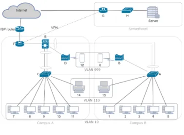
In this section, we construct the network model layer by layer based on the basic network displayed in Figure 1. Throughout the following subsections, we discuss our model layer by layer with the addition of the Physical layer, in which we consider the following basic network topology:
Physical layer
In the physical layer topology, the directly connected devices play a role. Therefore, WLAN connections and connections above any ISP services, including the Internet, arenot considered. The topology is represented as an undirected graph.
For the case study, as displayed in Figure 2, smartphones with numbers 6 and 12 are stan- dalone nodes, while there is no direct connection between any campus and the Server- hotel. The adjacency matrix has nodes. Of course, in a real enterprise environment, it is relevantfor campuses to have their separate adjacency matrices.
Figure 1. Basic network example to demonstrate the network model.
Figure 2. Physical layer topology.
Network access layer
The following assumptions in thegiven case study provide the basis for creating the graph structure in the Network access or Datalink layer:
- There are two VLANs as VLAN10 and VLAN110 configured on switch A and C. Both are active on router E.
- On switch C, client separation is active.
- On network devices, the admin access interface is disabled.
- On switch infrastructure, MSTP operates.
There is a clear difference between endpoints and infrastructure nodes as endpoints com- municate, while infrastructure elements help them. Hypothetically, an infrastructure node, which has an active management interface in a given VLAN, is a communication endpoint only in that VLAN. Thus, for modelling the two topologies in the Datalink layer, we distinguish the infrastructure topology D1(the left side of Figure 3) containing each node and the endpoint topology D2 (the right side of Figure 3) that contains nodes that communicate with each other.
However, comparing the Datalink layer to the Physical layer, the adjacency matrices of both graphs are expanded as each VLAN creates a separate network. As a result, for ex- ample, instead of dealing with simply “switch A”, one must consider “A VLAN10” and
“A VLAN110”, too.
The collision domains are represented with D1 edges. On the other hand, a broadcast domain is the subset of the Datalink adjacency matrix where if localhost connections are disabled and if at least one localhost connection is enabled.
Internet layer
The previously discussed schema, as there is a difference between endpoints and infra- structure nodes, is also valid in the Internet layer. Parallelly, we distinguish the infra- structure topology IP1 (the left side of Figure 4) containing each node and the endpoint topology IP2 (the right side of Figure 4) that contains those nodes which take part in the communication. Hypothetically, an infrastructure node, which has an active manage- ment interface in a given VLAN, is a communication endpoint only in that VLAN.
Figure 3. Datalink layer topologies (infrastructure vs communicating nodes).
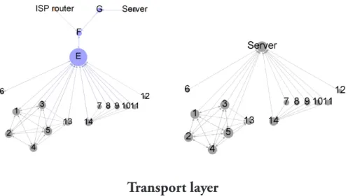
Transport layer
Unlike the Network access and the Internet layer, the Transport layer provides an end-to- end communication mechanism. Therefore, instead of differentiating between infrastruc- ture and communication endpoints, two essential protocols must be counted.
For the case study network, as an assumption, the transport layer protocol and ports displayed in Table 1 are enabled. The TCP and the UDP communication nodes are rep- resented respectively by the left and right side of Figure 5.
Application layer protocol
Transport layer protocol and port
Source Target
Netbios
udp/137 udp/138 tcp/139
1, 2, 3, 4, 5 1, 2, 3, 4, 5
DNS tcp-udp/53 1, 2, 3, 4, 5, 6, 7, 8, 9, 10, 11, 12 Server
LDAP(S) tcp/389
tcp/636 1, 2, 3, 4, 5, 6, 7, 8, 9, 10, 11, 12 Server
LPR tcp/9100 1, 2, 3, 4, 5 13
7, 8, 9, 10, 11 14
SMB tcp/445 1, 2, 3, 4, 5, 6, 7, 8, 9, 10, 11 Server HTTPS tcp/443 1, 2, 3, 4, 5, 6, 7, 8, 9, 10, 11, 12 Server
VPN udp/4500 F G
G F
Figure 4. IP layer topologies (infra- structure vs communicating nodes).
Table 1. Transport and application layer connections.
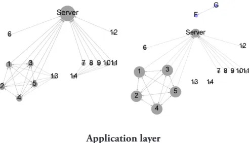
Application layer
The transport layer protocols precisely determine their connection with the application layer via port numbers, as Table 1 displays specifically for the case study. However, there are certain cases when one application applies more transport-level protocols, e.g., the Netbios. Figure 6 displays the Application layer graph.
Analysis of the model
T
raditionally, one of the main conceptual problems in connection with security is the usage and application of terminology because it is sometimes inaccurate, or there can even be simple misunderstandings or misconceptions among affected parties(Ekelhart et al., 2006). However, the complexity of the applied ICT services and, hence, the servic- ing infrastructure that is composed ofseveral essential structural elements is constantly increasing (Kadry and Hassan, 2008).The concept of network layers, as a framework, helps to reduce the complexity of network interactions. With regard to the profound interconnecting and interrelating manner of today’s ICT services and their components, the direction and the nature of the connections determine the topology.In general, one represents the nodes’ interconnections simply in one topology figure or table despite the TCP/IP model’s encapsulation, which is its most vital characteristic feature. Essentially, it is the method with which each lower layer serves the layer or layers above it, while at the same time, each layer communicates with its corresponding layer on the other node. This fact ensures that each layer has its separate topology such as point-to- point, point-to-multipoint, bus, star, ring, hierarchical, or mesh, being part of the overall complex system to operate the network. Therefore, it is not enough to represent an IT network with a simple topology represented by a graph. One should model such complex networks with a multipartite graph. Furthermore, the Network access layer and the Inter-
Figure 5. Transport layer topolo- gies (TCP vs UDP communication nodes).
Figure 6. Application layer topology.
net layer have two rival models: the infrastructure model and the model of the endpoints of the communication. The infrastructure models and the models of the communication endpoints must be applied, respectively.
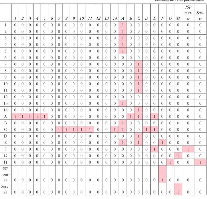
Table 2 represents the connections of the physical layer discussed in the case study; how- ever, each layer may differ in the way it connects network entities with the rule of upper layers dependence on lower layers.
1 2 3 4 5 6 7 8 9 10 11 12 13 14 A B C D E F G H ISP rout- er
Serv- er
1 0 0 0 0 0 0 0 0 0 0 0 0 0 0 1 0 0 0 0 0 0 0 0 0
2 0 0 0 0 0 0 0 0 0 0 0 0 0 0 1 0 0 0 0 0 0 0 0 0
3 0 0 0 0 0 0 0 0 0 0 0 0 0 0 1 0 0 0 0 0 0 0 0 0
4 0 0 0 0 0 0 0 0 0 0 0 0 0 0 1 0 0 0 0 0 0 0 0 0
5 0 0 0 0 0 0 0 0 0 0 0 0 0 0 1 0 0 0 0 0 0 0 0 0
6 0 0 0 0 0 0 0 0 0 0 0 0 0 0 0 0 0 0 0 0 0 0 0 0
7 0 0 0 0 0 0 0 0 0 0 0 0 0 0 0 0 1 0 0 0 0 0 0 0
8 0 0 0 0 0 0 0 0 0 0 0 0 0 0 0 0 1 0 0 0 0 0 0 0
9 0 0 0 0 0 0 0 0 0 0 0 0 0 0 0 0 1 0 0 0 0 0 0 0
10 0 0 0 0 0 0 0 0 0 0 0 0 0 0 0 0 1 0 0 0 0 0 0 0
11 0 0 0 0 0 0 0 0 0 0 0 0 0 0 0 0 1 0 0 0 0 0 0 0
12 0 0 0 0 0 0 0 0 0 0 0 0 0 0 0 0 0 0 0 0 0 0 0 0
13 0 0 0 0 0 0 0 0 0 0 0 0 0 0 1 0 0 0 0 0 0 0 0 0
14 0 0 0 0 0 0 0 0 0 0 0 0 0 0 0 0 1 0 0 0 0 0 0 0
A 1 1 1 1 1 0 0 0 0 0 0 0 0 0 0 1 1 0 1 0 0 0 0 0
B 0 0 0 0 0 0 0 0 0 0 0 0 0 0 1 0 0 0 0 0 0 0 0 0
C 0 0 0 0 0 0 1 1 1 1 1 0 0 1 1 0 0 1 1 0 0 0 0 0
D 0 0 0 0 0 0 0 0 0 0 0 0 0 0 0 0 1 0 0 0 0 0 0 0
E 0 0 0 0 0 0 0 0 0 0 0 0 0 0 1 0 1 0 0 1 0 0 0 0
F 0 0 0 0 0 0 0 0 0 0 0 0 0 0 0 0 0 0 1 0 0 0 1 0
G 0 0 0 0 0 0 0 0 0 0 0 0 0 0 0 0 0 0 0 0 0 1 0 0
H 0 0 0 0 0 0 0 0 0 0 0 0 0 0 0 0 0 0 0 0 1 0 0 1
ISP rout-
er 0 0 0 0 0 0 0 0 0 0 0 0 0 0 0 0 0 0 0 1 0 0 0 0
Serv-
er 0 0 0 0 0 0 0 0 0 0 0 0 0 0 0 0 0 0 0 0 0 1 0 0
Conclusion
T
oday’s IT networks are complex systems with various endpoint machines and inter- mediate network devices. However, there are basic rules and factors to be considered when planning and operating such a network that fundamentally define today’s network communications. This paper reviewed several of them with regard to the TCP/IP model.The Network access layer provides basic error checking and, in some cases, correction algorithms and defines further attributes as possible packet size and their construction.
Table 2. Connection matrix of the case study network’s physical layer.
Furthermore, its applied protocol defines the Network access layer’s topology with its collision domains. Assuming a correctly set Spanning Tree Protocol, the Network access layer’s arrangements can change dynamically due to defects in a network line or network device if no line redundancy is applied.
The Internet layer exchanges datagrams from the originating host to the destination host or hosts across network boundaries. The Internet layer usesthe IP addressing schemes applying the network prefix and host identifier. Among IP domains, the routing infra- structure creates the connections and separates the broadcast domains even with the ap- plication of VLANs. Furthermore, regardless of the operating layer protocol, the VPNs, e.g., L2F, IPsec, or SSL VPN, connect seemingly separate private segments in the world.
The Transport Layer provides host-to-host communication with additional services de- pending on the applied protocol. Transmission Control Protocol (TCP) is for reliable, connection-oriented data transport with flow-control and same-order delivery. User Datagram Protocol (UDP) provides unreliable, connectionless transport. Based on the services of the Transport layer, the Application Layer includes applications, processes, or system services or daemons. In order to carry outits tasks, it also defines protocols that applications use to communicate in a host-to-host communication
Hierarchical network design involves dividing the network into discrete functioning lay- ers, in which each layer provides specific functions such as end-user devices’ accessing, network distributing, or server side networking. This approach elevates manageability, performance, and security purposes, reaching required resiliency and flexibility. Security controls such as endpoint isolation and HTTP proxies fundamentally affect network to- pologies, too. However, knowing the accurate network topology helps network architects plan security controls and first-line incident respondents to interpret information and prevent further contamination.
However, in general, one represents network topology in a universal figure or table. This paper states that each layer in the TCP/IP model has its separate topology, which may change dynamically. Therefore, a simple topology does not represent the complexity and actual operation of a network. One should model such a complex network with a mul- tipartite graph that represents the TCP/IP layers, differentiating the infrastructure and endpoints models in the Network access and Internet layers.
As future work, we intend to apply the above model as the base for formal structural analysis on a real network along with gathering and associating metrics about infrastruc- tural elements.
Funding
This research was supported by the ERDF project “CyberSecurity, CyberCrime and Critical Information Infrastructures Center of Excellence” (No. CZ.02.1.01/0.0/0.0/16_019/0000822).
Contributions
Writing, methodology, original draft preparation by ZB; conceptualisation, writing, funding acqusition, validation by TS; All authors have read and agreed to the published version of the manuscript.
Data Availability Statement Not applicable.
Disclosure statement
No potential conflict of interest was reported by the authors.
References
Anyasi, F.I., Uzairue, S.I., Enehizena, O.N., Matthews, V.O., Amaize, P. and Nkordeh, N. (2018) ‘De- sign and analysis of a broadcast network using logical segmentation’, Telkomnika, 16(2), pp. 803–810. doi:
10.12928/telkomnika.v16i2.8461.
Cisco (2014) ‘Hierarchical network design’, in Cisco Networking Academy, Connecting Networks Companion Guide, Hoboken: Pearson Education, Cisco Press, pp. 4–7.
Cisco Systems (2017) ‘Spanning tree protocol – Cisco’, Cisco Support. Available at: https://www.cisco.com/c/
en/us/support/docs/lan-switching/spanning-tree-protocol/10556-16.html (Accessed: 15 August 2021).
Ekelhart, A., Fenz, S., Klemen, M.D. and Weippl, E.R. (2006) ‘Security ontology: Simulating threats to cor- porate assets’, in A. Bagchiand and V. Atluri (eds.), Lecture Notes in Computer Science (Including Subseries Lecture Notes in Artificial Intelligence and Lecture Notes in Bioinformatics). Berlin, Heidelberg, Springer, pp. 249–259.
doi: 10.1007/11961635_17.
IEEE (Institute of Electrical and Electronics Engineers) (2000) ‘IEEE 802.3ad-2000 – IEEE standard for information technology – Local and metropolitan area networks’. IEEE.
IEEE (Institute of Electrical and Electronics Engineers) (2001) ‘IEEE standard for local and metropolitan area networks – Common specification. Part 3: Media access control (MAC) bridges – Amendment 2: Rapid reconfiguration’, IEEE Std 802.1w-2001. IEEE. doi: 10.1109/IEEESTD.2001.93287.
IEEE (Institute of Electrical and Electronics Engineers).(2002) ‘IEEE standards for local and metropolitan area networks – Virtual bridged local area networks – Amendment 3: Multiple spanning trees’, IEEE Std 802.1s-2002 (Amendment to IEEE Std 802.1Q, 1998 Edition). IEEE. doi: 10.1109/IEEESTD.2002.94223.
IEEE (Institute of Electrical and Electronics Engineers) (2012) ‘IEEE standard for local and metropolitan area networks-media access control (MAC) bridges and virtual bridged local area networks –Amendment 20:
Shortest path bridging’, IEEE Std 802.1aq-2012 (Amendment to IEEE Std 802.1Q-2011 as amended by IEEE Std 802.1Qbe-2011, IEEE Std 802.1Qbc-2011, IEEE Std 802.1Qbb-2011, IEEE Std 802.1Qaz-2011, and IEEE Std 802.1Qbf-2011). doi: 10.1109/IEEESTD.2012.6231597.
IEEE (Institute of Electrical and Electronics Engineers) (2014a) ‘IEEE standard for local and metropolitan area networks-bridges and bridged networks’, IEEE Std 802.1Q-2014 (Revision of IEEE Std 802.1Q-2011).
doi: 10.1109/IEEESTD.2014.6991462.
IEEE (Institute of Electrical and Electronics Engineers) (2014b) ‘IEEE 802.1AX-2014 – IEEE standard for local and metropolitan area networks – Link aggregation’. IEEE.
IETF (Internet Engineering Task Force) (1981) RFC 791. Available at: https://tools.ietf.org/html/rfc791 (Ac- cessed: 15 August 2021).
IETF (Internet Engineering Task Force) (1999) RFC 2663. Available at: https://tools.ietf.org/html/rfc2663 (Accessed: 15 August 2021).
IETF (Internet Engineering Task Force) (2010) RFC 5798. Available at: https://tools.ietf.org/html/rfc5798 (Accessed: 15 August 2021).
IETF (Internet Engineering Task Force) (2017) RFC 8200. Available at: https://tools.ietf.org/html/rfc8200 (Accessed: 15 August 2021).
Imran, M., Alghamdi, A. and Ahmad, B. (2015) ‘Role of firewall technology in network security’, Interna- tional Journal of Innovation & Advancement in Computer Science, 4(12), pp. 3–6.
International Organization for Standardization (2013) ‘ISO/IEC 2382-36:2013 – Information technology – Vocabulary’. ISO.
Jaha, A.A., Shatwan, F.B. and Ashibani, M. (2008) ‘Proper virtual private network (VPN) solution’, in Pro- ceedings – The 2nd International Conference on Next Generation Mobile Applications, Services, and Technologies, NGMAST 2008. doi: 10.1109/NGMAST.2008.18.
Jeffree, T., Congdon, P. and Seaman, M. (2010) ‘802.1X-2010 IEEE standard for local and metro- politan area networks – Port-based network access control’, IEEE Std 802.1X-2010. IEEE. doi: 10.1109/
IEEESTD.2010.5409813.
Joint Task Force Transformation Initiative (2011) SP800-39 Managing information security risk: Organiza- tion, mission, and information system view. NIST Special Publication. Gaithersburg: National Institute of Stan- dards and Technology, Gaithersburg. doi: 10.6028/NIST.SP.800-39.
Kadry, S. and Hassan, W. (2008) ‘Design and Implementation of system and network security for an enter- prise with worldwide branches’, Journal of Theoretical & Applied Information Technology, 4(11), pp. 1361–1370.
Lantto, H., Åkesson, B., Suojanen, M., Tuukkanen, T., Huopio, S., Nikkarila, J-P. and Ristolainen, M.
(2019) ‘Wargaming the cyber resilience of structurally and technologically different networks’, Security and Defence Quarterly, 24(2), pp. 51–64. doi: 10.35467/sdq/103346.
National Institute of Standards and Technology (2020) Zero Trust Architecture –Draft, 2nd ed. NIST Spe- cial Publication 800-207. Gaithersburg: National Institute of Standards and Technology. doi: 10.6028/NIST.
SP.800-207-draft2.
Perlman, R. (2004) ‘Routing protocols’, in Computer Science Handbook, 2nd ed. Boca Raton: CRC Press. doi:
10.1201/b16812-53.
Pilarski, G. (2016) ‘Tackling cyberspace threats – The international approach’, Security and Defence Quarterly, 12(3), pp. 100–117. doi: 10.35467/sdq/103238.
Ravali, P. (2013) ‘A comparative evaluation of OSI and TCP/IP models’, International Journal of Science and Research, 4(7), pp. 514–521.
Rueda, D.F., Calle, E. and Marzo, J.L. (2017) ‘Robustness comparison of 15 real telecommunication net- works: Structural and centrality measurements’, Journal of Network and Systems Management, 25, pp. 269–289.
doi: 10.1007/s10922-016-9391-y.
von Roessing, R. (2010) ‘The ISACA business model for information security: An integrative and innovative approach’, in N. Pohlmann, H. Reimerand W. Schneider (eds.), ISSE 2009 Securing Electronic Business Processes, Vieweg+Teubner, Wiesbaden. pp. 37-47. doi: 10.1007/978-3-8348-9363-5_4.
Singh, S., Mudgal, P., Chaudhary, P. and Tripathi, A.K. (2015) ‘Comparative analysis of packet loss in LAN’, International Research Journal of Computers and Electronics Engineering, 3(1), pp. 12–16. doi:
10.5120/20525-2858.
Stadler, R., Pasquini, R. and Fodor, V. (2017) ‘Learning from network device statistics’, Journal of Network and Systems Management, 25(4), pp. 672–698. doi: 10.1007/s10922-017-9426-z.
Voloshin, V.I. (2009) Introduction to Graph Theory. New York: Nova Science. doi: 10.2307/3620453.
White, R. and Donohue, D. (2014) The Art of Network Architecture, The: Business-Driven Design. Indianapolis:
Cisco Press.