An International Journal for Engineering and Information Sciences DOI: 10.1556/606.2020.15.3.15 Vol. 15, No. 3, pp. 150–161 (2020) www.akademiai.com
INVESTIGATION OF THE WARPING TORSION OF A PRESS MACHINE
1 Antal Gábor ERDŐS*2 Károly JÁRMAI
1,2 Department of Chemical Engineering, Faculty of Mechanical Engineering and Information Technology, University of Miskolc, 3515 Miskolc-Egyetemváros, Hungary
e-mail: 1vegyerda@uni-miskolc.hu, 2altjar@uni-miskolc.hu Received 5 December 2019; accepted 18 March 2020
Abstract: In this article, the investigation of a press machine with 30 tons of pressing weight is presented. The beam of this machine is an I-beam, which has an open cross-section. It is known that this version of cross-section is sensitive to torsional stress. The stress from warping torsion is normal stress, so the opened cross-section is more sensitive to this type of stress. The bimoment that causes normal stress can also be very high, so dealing with this stress is very important.
Keywords: Warping torsion, Press machine, Opened cross-section, Numerical simulation, Finite element method, Optimization
1. Mechanical model
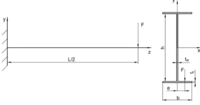
In the industry, press machines for sheet forming are still used today, and there is one type of these device in which the tool is moved instead of the workpiece, as it is shown in Fig. 1. For these machines, the tool carrier must be made of a movable section, for example in section 1. Most often, a bracket or fork support is used to hold the beam. In this article, the investigation of an I-beam with a fixed support at both end will be carried through. For the calculations the half of the beam was used.
When subjected to torsion stress, depending on the boundary conditions, two primary cases can be distinguished, one free twist (or Saint-Venant torsion) and the warping or mixed torsion. It differs in the displacement in the direction of the longitudinal axis of the beam. In case of free or Saint-Venant torsion, this displacement
* Corresponding Author
is not prevented. And because of the boundary conditions of the beam, the torsion is a warping torsion as it can be seen in the mechanical model and the geometry of the cross-section in Fig. 1 [1].
Fig. 1. Mechanical model and the cross-section
The target of the investigation was a press machine with 30 tons of pressing weight, and the tool has moving mechanism, which held by two I-beams whose lies parallel to each other. Because of the eccentric force transfer, the stress of the beam comes from three sources: bending, shear stress from torsion and the warping torsion.
The control of the analytical calculations also happened with Finite Element Method (FEM), and for that, the ANSYS 2019 R1 Code was used. The boundary condition the following fixed support was at one end of the beam, and on the other end, the load was applied was a frictionless support. This load always was moment type load for better results and to avoid the singularity. This moment was the torsional moment or the bending moment depending on the stress what wanted to be checked. The loads were applied together in the case of reduced stress. Two mesh types have also been used as a hexagonal dominant method called ‘Hex dominant method’ and ‘Tetrahedrons’ for the mesh independence of the results. The results were the same in each case.
2. Stress calculations
2.1. Warping torsion
The eccentricity is sixth of parameter b, which is the width of the flange. The primary differential equation of the warping torsion is [1], [2], [3]:
. (1)
The general solution for this type of differential equation is:
sinh cosh . (2)
The value of constant is:
" #!!. (3) The other three constants can be determined by the boundary conditions and the derivatives of the general solution. The boundary conditions for the bricked support can be seen in Table I.
Table I
Boundary conditions for the bricked supports [1]
φ is the rotation φ’ is the displacement φ’’ is the stress
If z = 0 0 0 not 0
If z = L/2 not 0 0 not 0
For the application of the boundary conditions, the first and the second derivate of the general solution is needed. The first derivative of Eq. (2),
$
$ cosh sinh . (4)
The second derivative of Eq. (2):
$%
$ % sinh cosh . (5)
To calculate the C1, C2, C3constants its expedient to deal with cases where the value of the derivatives are 0. The C3constant from the first derivative in case of z = 0
" #!!,. (6)
The C1 and C4 constants could be calculated with the first derivative and the general solution, when z = L/2:
1%234562,7%89 8 , 5:;62,7%8
!
" #!
234562,7%89 8
, 5:;62,7%8 . (7)
The value C1 is equal to:
1%234562,7%89 8 , 5:;62,7%8
!
" #!
234562,7%89 8
, 5:;62,7%8 . (8)
The bimoment can be calculated with the formula below:
< = > ?C @AB %%. (9)
From the stress diagrams it can be seen that the maximum value of the bimoment rises at the fixed end of the beam, where z = 0. To determine it, the second derivate needs to be calculated at the point of fixed end, here z = 0.
< z D " #!!, EFGℎ " #!! 234562,, 5:;62,7%89 87
%8 IJEℎ K. (10)
After simplification, the above relationship can be obtained. The normal stress from warping torsion:
> L#MM ?, (11)
where Iω is the resistance of the cross-section against the warping torsion, and the ωt is the degree of torsion. The resistance depends on the geometry and the type of the cross- section, which could be opened or closed. The I-beam cross-section is opened.
The distribution of the normal stress and the degree of torsion can be seen in Fig. 2 and as it can be seen the maximum value of the stress occurs at the edge of the flange.
The degree of torsion also is a function of the geometry of the cross-section.
Fig. 2. The degree of torsion of an I-beam and the stress distribution from warping torsion (on the basis of [1])
The degree of torsion is also concern on the flange. Its value is equal to the double of the sector area that belongs to the given arc that points from the shear center of the cross-section to the given point. The shear center is at the intersection of the symmetry lines if the cross-section has doubly symmetrical. If not so, the cross-section has only one symmetric axis, the position of the shear center has to be determined by analytic way with the equation below:
Q@ #R = ?C S QAB. (12)
The investigation was carried through with a cross-section which has two symmetric lines, and in this case of an I-beam, the degree of torsion could be calculated with the formula below:
? = TXW @AE U V. (13)
The resistance of an I-beam against the warping torsion is:
4 = ?XU/ YZA[ V%U \. (14)
The calculated results can be seen in Table II, and the results from the FEM are presented in Fig. 3.
Table II
Results of the analytical calculations of the warping torsion
Calculated quantity
resistance against the
warping torsion
? is the degree
of torsion
< ]W^
maximum value of
the bimoment
Fs the resistance
against the torsion
torsional moment
> normal stress from the warping torsion Results 6.51·1012
mm6
6.25·104 mm2
6.008·109 Nmm2
7.5·105 mm4
6.25 kNm
57.679 MPa
Fig. 3. FEM result for the warping torsion
2.2. Shear stress from the torsion
Beside of the bimoment from the warping torsion, the beam also exposed to the significant torsional moment that comes from the eccentric load of the beam, this load is equal to the loading force multiplied by the eccentricity. The value of this eccentricity is the sixth part of the width of the flange, which is the parameter b. The worst-case scenario is when the load occurs at the half of the beam, which length is 2000 mm, this is parameter L/2. The load is half of the pressing weight because two I-beams lie parallel to each other, so the load is 150 kN on one beam. The shear stress form the torsion also distributes into two parts between the two fixed end.
The shear stress from torsion at one fixed end is:
_ !#!. (15)
This equation gives the amount of the shear stress of a plate with thickness t in case of an opened cross-section. The resistance against the torsion in the same case [4]:
`X X ∑ bd cYc
ce , (16)
where η0 is the form factor; α0 depends on the manufacturing procedure and its value is 1.5 for welding beam; and 1.2 for rolled ones. In the formula (17) ti is always the thickness of the i-th plate element of the cross-section and bc is always the width of the plate [4].
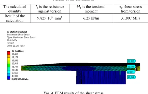
The calculated values are presented in Table III, and the result from the ANSYS can be seen in Fig. 4.
Table III Results of the calculations The calculated
quantity
is the resistance against torsion
is the torsional
moment _ shear stress from torsion Result of the
calculation 9.825·105 mm4 6.25 kNm 31.807 MPa
Fig. 4. FEM results of the shear stress
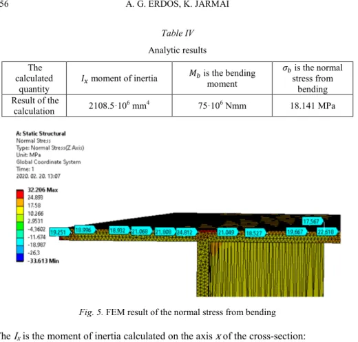
2.3. The normal stress from bending
The stress from the bending can be calculated with the below formula:
>U i2j%k\8
#l . (17)
In that equation, the mℎ/2 YZn sum is the distance between the center of gravity and the extreme fiber. In case of the beam with two fixed ends and the load is one concentrated force in the middle of the beam the bending moment is:
U o7%27%8%
p% . (18)
The results of the calculations can be seen in Table IV, and the FEM results are presented in Fig. 5.
Table IV Analytic results The
calculated
quantity ^
moment of inertia U is the bending moment
>U is the normal stress from
bending Result of the
calculation 2108.5·106 mm4 75·106 Nmm 18.141 MPa
Fig. 5. FEM result of the normal stress from bending
The Ix is the moment of inertia calculated on the axis x of the cross-section:
^ V r 2 s\ U YZ b 2V \8 t. (19)
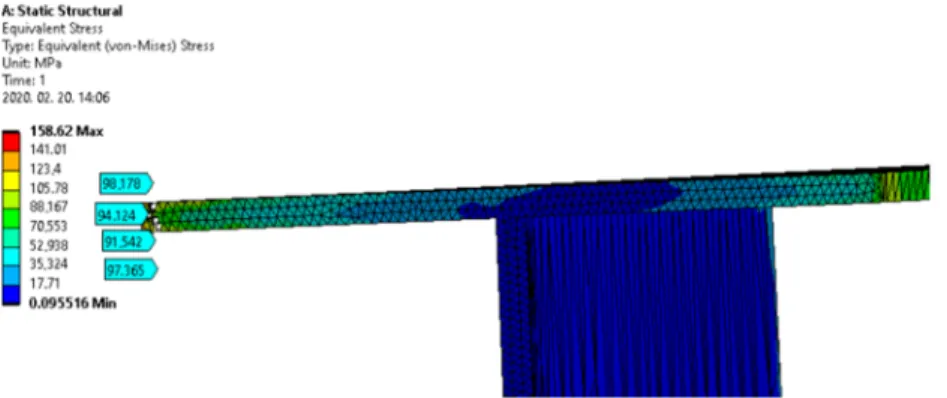
2.4. The reduced stress
The reduced stress can be calculated according to von Mises [4]:
>uv w > > > > > > 3 _ _ _ . (20)
The normal stress does not appear outside the z-direction, and the shear stress also has no component in x-direction. In this case, the reduced stress could be calculated with a more straightforward formula:
>uv √> 3 _ . (21)
This stress should be compared with the allowed stress that specific to the chosen steel. The value of the reduced stress was 94.898 MP. For the calculations S235 structural steel was selected, its yield strength is 235 MPa, and the safety factor was 1.2, and with these values, the allowed stress was 195.8 MPa. The FEM result can be seen in Fig. 6.
Fig. 6. FEM results of the reduced stress
3. The deflection of the beam
The total deflection of the beam also came from three sources: bending, warping torsion and the shear stress. The simplest is to calculate the deflection from bending, in this case, the deflection for this boundary condition and it is different because of the load; it is different for direct force load and moment type load. For the FEM to avoid the singularity, the moment type load was chosen for the calculations. The deflection from the bending is:
y o 27%8
%27%8%
z #lp . (22)
As it was mentioned before, the first derivate of the general solution of the basic differential equation of the warping torsion gives the displacement at a given point can be calculated:
y , ?. (23)
The value of the displacement of the beam at the half point is 0 because of the boundary conditions, but it can be complete at a discreet distance, the value of it was second-order small. The constants are the same as determined before. If the dimension of this quantity gets checked, it can be determined; it has a dimension 1/mm. But the deflection has a dimension in mm, so the first derivative must be multiplied with the degree of torsion. With this formula the deflection of the flange plate can be determined in different points; it has its maximum value at the edge of the flange where the degree of torsion also has its maximum value.
The last one is the deflection from the shear stress. This can be calculated with the equation below [5]:
y o p/ {} " C~| 2 I , (24)
•€ C
#l%= 2C •l%8 AB, (25)
where A1 is the area of the cross-section, which is subjected to shear stress, and ρq is the shear stress distribution factor, and cl is a factor that depends on the length of the distributed load. For the calculations, the value of cl was 1 [6].
In (25) Sx is the static moment of the cross-section calculated on the axis x, the calculation of this integral was carried through with the split of the cross-section into three pieces, the flanges made two pieces, and the web plate was the third. After getting the total value of the integral must be added to the components. The results of the calculation can be seen in Table V, and the FEM results can be seen in Fig. 7.
Table V
Results of the calculation of the deflection The calculated
quantity y deflection from
bending y deflection from
warping torsion y deflection from shear stress Result of the
calculation 0.11856 mm 1.879·10-2 mm 0.202 mm
Fig. 7. Simulated results of the deflection
4. Fatigue calculations
The fatigue calculations were carried through according to the Eurocode 3 part 1-9.
To calculate the number of cycles, the rearrangement of the formula of the stress amplitude happened to make the calculations of the number of cycles possible. This formula for the stress amplitude can be seen below:
‡Jˆ∆>d ‡Jˆ 2 ‹XŠ8 ‡Jˆ∆>1, (26)
‡Jˆ∆>d Œ ‡Jˆ 2Œ X‹Š8 ‡Jˆ∆>•, (27)
where m is the steepness of the fatigue curve, and its value can be 3 or 5, ∆σc is the fatigue class of the steel structure.
For the calculations, the 125 class was chosen. The class gives the stress amplitude at the reference number of cycles which is 2·106 was chosen. For the calculations, the stress amplitude was equal to the reduced stress what was calculated before. After rearranging the equation to calculate the number of cycles for the case where m = 3 this is the case can be used while the reduced stress is higher than the stress amplitude that describes the chosen class:
• X ‘’“”•–—˜‘’“∆”™XŠ , (28)
and
• Xš ‘’“”•–—˜‘’“∆”›Œ XŠ . (29)
The formula above on the left is valid while the calculated value of the reduced stress is higher than the detail category, which is 125 if it is less. However, still more than the cut-off limit in this case the m is equal to 5 and ∆σD should be used instead of
∆σC, and the reference number of cycles is 5·106, where ∆σD is the constant amplitude fatigue limit. In this case, the number of cycles could be calculated with the formula on the right [7].
The third case when the reduced stress is below the cut-off limit, then the fatigue is not a relevant issue.
5. Optimization
The optimization aimed to determine the geometry of the cross-section of the I-beam, which means four variables in the cross-section with two symmetric lines. The h is the width of the web plate, tw is the thickness of the web plate, the tf is the thickness of the flange plates, and the b is the width of the flange plates. The objective functions to be minimized/maximized were the number of cycles (lifetime), the area of the cross-section (mass of the beam) and the deflection. The number of cycles could be as high as possible because this is the lifetime of the machine, and the deflection should be minimal. These two objectives try to increase the geometric parameters, and the minimization of the area of the cross-section works just the opposite. So, the task is a multi-objective optimization. Resolving inconsistencies and managing the objectives, the normalized objective method was used. This method summarizes the values of each objective multiplies it by a weighting factor, which gives the importance of the objective and distributes with a scaling factor, which meaning the normalization. This method eliminates the difference in the magnitude of the values of the objectives. The results of the optimization can be seen in Table VI and Table VII with two different cases of the weighting factors. These weighting factors can be changed according to the needs of the user. For this procedure, the Microsoft Excel Solver was used, and within it, the Nonlinear General Reduced Gradient method. The formulae for the optimization are the follows [1], [7], [8]:
[ ∑ ¡¢ZZ¢^
¢£
uce , (30)
∑ ¤uce c 1, (31)
cX≠ 0 and ¤c≥ 0. (32)
The conditions that determine the allowed values of the variables were the followings: the buckling conditions from the Eurocode 3; the reduced stress have to be lesser than the yield strength of the steel distributed by the safety factor, which value was 1.2. The buckling conditions are [9]:
V
r≤ 69ª. (33)
U
\≤ 28ª. (34)
where ε ,the buckling factor is equal to:
ª w Œ ¬WZR . (35)
There were geometric conditions for the variables; it can be seen in Table VI. But it has to be mentioned, that these conditions also can be changed to fit the needs of the user. The result can be seen in Table VII.
Table VI
Conditions for the geometric variables Condition for the
geometric
quantity h ≤ 1000 mm 250 mm ≤ b 5 mm≤ tf ≤60 mm 5 mm≤ tw ≤60 mm Table VII
Results of the optimization with 0.1;0.1;0.8 weighting factors Constants for
normalization Weighting factors Objective Optimum sizes Area of the cross-
section 1000 0.1 h=395.874 mm
Number of cycles 100000 0.1 6.906 b=250 mm
Deflection 1 0.8 tf=12.508 mm
tw=5.737 mm
6. Conclusion
In the article an investigation of an I-beam was carried out. The numerical calculation of the stresses and the validation of the calculations with FEM using ANSYS 2019 R1 software were developed. After the calculation of the deflection the results were checked with two different types of mesh to validate the calculation. The
differences between the calculated and the simulated results could come from the mechanical model, which is over-determined. The lifetime of an expensive machine is also a crucial parameter and its analysis was carried through based on Eurocode 3. The calculated results give the optimum of the cross-section considering several constraints.
The best cross-section in different cases has been determined. Different cases can be dealt using the weighting factors, making the difference between the objectives by the user. These weighting factors represent the importance of the objectives.
Acknowledgement
The described article was carried out as part of the EFOP-3.6.1-16-2016-00011
‘Younger and Renewing University - Innovative Knowledge City - Institutional development of the University of Miskolc aiming at intelligent specialization’ project implemented in the framework of the Széchenyi 2020 program. The realization of this project is supported by the European Union, co-financed by the European Social Fund.
Open Access statement
This is an open-access article distributed under the terms of the Creative Commons Attribution 4.0 International License (https://creativecommons.org/licenses/by/4.0/), which permits unrestricted use, distribution, and reproduction in any medium, provided the original author and source are credited, a link to the CC License is provided, and changes - if any - are indicated. (SID_1)
References
[1] Farkas J., Jármai K. Analysis and optimum design of metal structures, Balkema Publishers, Rotterdam, 1997.
[2] Skriko T., Björk T., Ahola A. On the distortion and warping of cantilever beam with hollow section, 72nd International Conference at International Institute of Welding, Bratislava, Slovakia, 7-12 July 2019, Vol. XV-1606-19, pp. 1‒15.
[3] Baláž I., Kováč M., Živner T., Koleková Y. Resistances of I-section to internal forces interactions, Key Engineering Materials, Vol. 710, 2016, pp. 309‒314.
[4] Muttnyánszky Á. Strength of structures, (in Hungarian) Műszaki Könyvkiadó, Budapest, 1981,
[5] Farkas J. Optimum design of metal structures, Ellis Horwood Publisher, Chichester, 1984.
[6] EN 1993-1-9, Eurocode 3, Design of steel structures-Part 1-9: Fatigue, 2005.
[7] Petrik M., Szepesi G., Jármai K. CFD analysis and heat transfer characteristics of finned tube heat exchangers, Pollack Periodica, Vol. 14, No. 3, 2019, pp. 165‒176.
[8] Virág Z. Determination of optimum diameter of a welded stiffened cylindrical shell, Pollack Periodica, Vol. 4, No. 1, 2009, pp. 41–52.
[9] EN 1993-1-5: Eurocode 3, Design of steel structures-Part 1-5: Plated structural elements, 2006.
![Fig. 2. The degree of torsion of an I-beam and the stress distribution from warping torsion (on the basis of [1])](https://thumb-eu.123doks.com/thumbv2/9dokorg/780401.35816/4.892.269.562.392.556/fig-degree-torsion-stress-distribution-warping-torsion-basis.webp)