REGULARARTICLE
Computer-aided design and loaded tooth contact analyses of bevel gear pair having straight teeth by different loaded torques
Sándor Bodzás*
Department of Mechanical Engineering, University of Debrecen, Debrecen, Hungary Received: 8 May 2019 / Accepted: 24 October 2019
Abstract.The aim of this publication is to show how to integrate the designing process of straight bevel gears into a computer software so it can be further used for making the three-dimensional (CAD) model of the gear pair. During meshing the driven and the driving gears engage gradually so contact points can be mathematically determined between the element pairs according to the developed coordinate system’s arrangement. With my- developed computer software, I designed a certain bevel gear pair having straight teeth. Naturally, many different types of this pair could be designed. After that Loaded Tooth Contact Analysis (LTCA) have been doneby normal stress, normal deformation and normal elastic strain parameters. The aim of the LTCA is the analysis of the connection tooth zone in mechanical aspects by different loads. If the received parameters are not appropriate, you can return to the mechanical designing process where the starting parameters of the gear could be modified. Different load torques were used to determine the established mechanical parameters of the elements.
Keywords:Bevel gear / module / LTCA / CAD / normal
1 Introduction
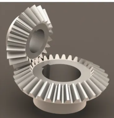
Straight bevel gears are applied widely in machinery (in vehicles, tool machines, for medical tools and machines etc.). They are used to connect shafts whose axes intersect in some angles, thus the meshing surfaces form a cone on which teeth are shaped (Fig. 1) [1–6].
One of the oldest process for producing gears applied even today is the ReineckerBilgram process. In this case, the vertical shaft of the machine intersects the centre of the pitch surface. The cutting tool makes an alternating movement while the operating pitch cone of the bevel gear unwinds the axoid of the deriving pitch cone (Fig. 2) [1,3–8].
During another production process of Heidenreich– Harbeck, the machine uses 2 cutting tools. This method is more advantageous because in this case the machine is moved in the axes perpendicular to the axes of the pitch surface. The machine is not set according to the l dedendum angle, and the grip of the tool is stricter (Fig. 3) [1,3–8].
The paths of the cutting tools are not parallel during production, but they intersect in 2⋅u angle, this is called planing angle, which can be calculated in the following way
[5] (Fig. 4):
arcu¼0:25⋅m⋅pþRe⋅sinl⋅tana0
Re⋅cosl ð1Þ
2 De fi ning the contact points
The profile curver!1R of the bevel gear wheel is made as a result of the movement of the machining tool and the unwinding movement for the K1R(x1R, y1R, z1R) rotating coordinate system related to the driver gear wheel.
I am looking for the surface connected to K2R coordinate system related to r!1R. I use the fact that the 2 surfaces during their movements coincide. Taking into consideration the following correlation [4,9]:
’2R¼i21⋅’1R ð2Þ I can state that the movement can be described with (’1) movement parameter [4,9,10].
The relative velocity between the 2 surfaces can be determined by the transformation between the rotating K1Rcoordinate system of the driver wheel and the rotating K2Rcoordinate system of the driven wheel [4,9]:
v2R
!ð Þ12 ¼ d
dtr2R! ¼ d
dtM2R;1R
⋅r!1R: ð3Þ
* e-mail:bodzassandor@eng.unideb.hu
©AFM,EDP Sciences2019
https://doi.org/10.1051/meca/2019076
M echanics
& I ndustry
Available online at:
www.mechanics-industry.org
Transformation matrices between the K1R and K2R coordinate systems (Fig. 5):
M2R;1R¼M2R;2S⋅M2S;1S⋅M1S;1R
¼
cosð’1RÞ⋅sinð’2RÞ cosð’1RÞ⋅cosð’2RÞ sinð’1RÞ 0 sinð’1RÞ⋅sinð’2RÞ sinð’1RÞ⋅cosð’2RÞ cosð’1RÞ0
cosð’2RÞ sinð’2RÞ 0 0
0 0 0 1
2 66 4
3 77 5
ð4Þ M1R;2R¼M1R;1S⋅M1S;2S⋅M2S;2R
¼
sinð’1RÞ⋅cosð’2RÞ sinð’1RÞ⋅sinð’2RÞ cosð’1RÞ 0 cosð’1RÞ⋅cosð’2RÞcosð’1RÞ⋅sinð’2RÞ sinð’1RÞ 0 sinð’2RÞ cosð’2RÞ 0 0
0 0 0 1
2 66 4
3 77 5
ð5Þ Taking into consideration the correlation between the velocity vectors of the relative movement in K1Rand K2R coordinate systems [4,9]:
v!1Rð Þ12 ¼M1R;2R⋅v!2Rð Þ12 ð6Þ
in K1R coordinate system, the relative velocity vector, based on(3)is:
v1R
!ð Þ12 ¼M1R;2R⋅ d
dtM2R;1R
⋅r!1R; ð7Þ
where P1kis the kinematic mapping matrix [4,9]:
P1k¼M1R;2R⋅ d
dtM2R;1R
ð8Þ On the tooth surfaces of the meshing teeth, contact points mutually covering each other can be determined by solving the connection equationwhich expresses the 1st Law of Contact and the vector-scalar function simultaneously [4,9]:
n!1R⋅v!1Rð Þ12 ¼n!2R⋅v!2Rð Þ12 ¼!n⋅!vð Þ12 : ð9Þ
3 Designing the computer program
Input data for designing the drive pair are:m module,z1
number of teeth of the driver bevel gear wheel,z2number of teeth of the driven gear wheel,croot clearance factor and thea0angle of contact [1,3–8].
For designing, the necessary geometrical correlations from technical literature was also used, which can be seen below based onFigures 1and5 [1,3–8]:
– the largest pitch circle diameters:
d01;2 ¼m⋅z1;2; ð10Þ Fig. 1. Angles and diameters of bevel gear.
Fig. 2. Reinecker–Bilgram principle [6].
Fig. 3. Heidenreich–Harbeck principle [6].
Fig. 4. Definition of planing angle.
–half pitch angle of the driver gear wheel:
d01 ¼atan z2
z1 ; ð11Þ
–half pitch angle of the driven gear wheel:
d02= 90°d01, (12)
–effective pitch surface radius:
Re¼
ffiffiffiffiffiffiffiffiffiffiffiffiffiffiffiffiffiffiffiffiffiffiffiffiffiffiffiffiffiffiffiffiffiffiffiffiffiffiffi d01=2
ð Þ2þðd02=2Þ2 q
; ð13Þ
–addendum on the largest diameter:
f0¼m; ð14Þ
–dedendum on the largest diameter:
l0¼ð1þcÞ⋅m; ð15Þ
– the largest tip circle diameters:
df1;2 ¼z1;2þ2⋅cosd01;2
⋅m; ð16Þ
– the largest root circle diameters:
da1;2¼z1;2⋅m2⋅l0⋅cosðd01;2Þ; ð17Þ – face width:
b¼ 1
3:5⋅Re; ð18Þ
– dedendum angle:
l¼atan l0
Re
; ð19Þ
– tip cone angles
df1;2¼d01;2þl; ð20Þ Fig. 5. Connection between the coordinate systems of the bevel gear drive pair.
–root cone angles:
dl1;2¼d01;2l: ð21Þ The output of my computer program is some calculated geometrical data of the bevel gear, and the profile curves (Fig. 6) in case of the smallest and largest diameters.
Knowing the above mentioned manufacturing technologies
[1,3–8] and the path of the cutting tool this program can determine the shape of the gear profiles.
The program saves the profiles of the bevel gear in .txt file format. Onto the given profile set of dots an interpolating B-spline can be fitted [11]. With the geometrical parameters of the drive pair and its profiles, the CAD model of the bevel gear was made by SolidWorks designing software (Fig. 7).
Fig. 6. Profile curves of the designed bevel gear pair (m= 15 mm,z1= 20,z2= 30,S= 90°). (a) Profile curves of the driver gear.
(b) Profile curves of the driven gear.
4 LTCA analysis
The aims of the so called“Loaded Tooth Contact Analysis”
(LTCA) are to model the connection of toothed drive pairs and to simulate the model by given loads and boundary conditions. During the LTCA in case of this given geometrical bevel gear (Figs. 6 and 7, Tab. 1) normal stress, normal elastic strain and normal deformation values were analysed on the surface of the driven and driver gear wheels [12–21].
4.1 Material quality, FE mesh (finite element)
The property of the material used for our bevel gear is given inTable 2.
During defining the FE mesh in the contact zone, sphere volume (37 mm radius) including dense triangles (1 mm mesh dimension) has been applied on the toothed area (Fig. 8). Automatic meshing was used on the outside areas.
The friction coefficient in the tooth contact zone ism= 0.01, because I considered the liquid and rolling frictions on the contact zone.
4.2 Loads and boundary conditions
Four coordinate systems have been defined for LTCAs: Ks absolute static, Ks1–static related to the driver wheel, Fig. 7. CAD model of the bevel gear pair having straight teeth
(m= 15 mm,z1= 20,z2= 30,S= 90°).
Table 1. Parameters of the designed bevel gear pair.
Parameters of the bevel gear pair Driver gear Driven gear
Module m= 15 mm
Number of teeth z1= 20 z2= 30
The largest pitch circle diameters d01= 300 mm d02= 450 mm
Half pitch angle of the pitch circle d01 ¼56:3° d02 ¼33:69°
Effective pitch surface radius Re= 270.416 mm
Addendum on the largest diameter f0= 15 mm
Dedendum on the largest diameter l0= 18 mm
The largest tip circle diameters df1= 316.64 mm df2= 474.96 mm
The largest root circle diameters da1= 280.03 mm da2= 420.04 mm
Face width b= 77.26 mm
Dedendum angle l= 3.8°
Tip cone angle df1= 60.11° df2¼37:49°
Root cone angle dl1 ¼52:5° dl2 ¼29:88°
Circular pitch on the largest pitch circle diameter t= 47.123 mm
Clearance atflank js= 2.356 mm
Pitch circle tooth thickness on the largest diameters Sax= 21.2 mm
Transmission i= 1.5
Ks2–static, related to the driven wheel and Kc–coordinate system in the tooth contact zone.
During the analyses, the gear having less number of teeth (driver gear) drives the gear having more number of teeth. Five degrees of freedom werefixed of the driver gear, only rotation along the rotational axis was allowed. The driver gear was loaded by M = 200–400 Nm torque by 50 Nm steps. Six degrees of freedom of the driven gear were fixed (Fig. 9).
4.3 Normal stress analyses
In afixed P point of the body,!rn signals the stress vector awakening on the !n normal surface elements. It can be divided into a normal directional component and one perpendicular to it [22–24] (Fig. 10):
rn
! ¼sn⋅! þn !tn ; ð22Þ
where the normal stress is [22–24]:
sn¼!n⋅!rn : ð23Þ
Normal stress partitions and average normal stress values have been detected as an effect of the different loads, on the tooth surfaces of the driver and driven gear (Fig. 11).
Results are shown in the diagram of Figure 12. In absolute value, as an effect of the increasing load moment, normal stress values also increase on the tooth surfaces of the driver and driven gear.
Table 2. Material properties.
Material quality Structured steel
Density 7850 kg/m3
Yield stress 250 MPa
Tensile strength 460 MPa
Poisson factor 0.3
Young modulus 200 GPa
Temperature 22°C
Fig. 8. FE mesh.
Fig. 9. Setting loads and boundary conditions.
Fig. 10. Defining normal stress.
The shapes of the two diagrams are the same and they are parallel. The normal stresses of the driven gear are a little higher than the normal stresses of the driver gear in absolute value. Because of the good comparison the same limits were set.
4.4 Normal elastic strain analyses
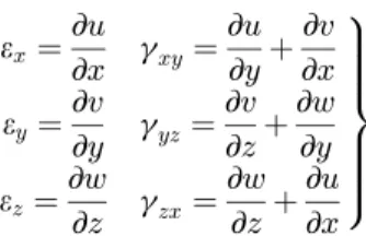
The state of a body’s deformation can be signalled by deformation tensor, which can be determined from the displacement vector as seen below [22–24]:
A¼1
2 !u°! þ∇ !∇°
!u
; ð24Þ
A¼
∂u
∂x
1 2
∂u
∂yþ∂v
∂x
1 2
∂u
∂zþ∂w
∂x
1 2
∂v
∂xþ∂u
∂y
∂v
∂y 1
2
∂v
∂zþ∂w
∂y
1 2
∂w
∂xþ∂u
∂z
1 2
∂w
∂yþ∂v
∂z
∂w
∂z 2
66 66 66 64
3 77 77 77 75
;
ð25Þ
where
ex¼∂u
∂x gxy¼∂u
∂yþ∂v
∂x ey¼∂v
∂y gyz¼∂v
∂zþ∂w
∂y ez¼∂w
∂z gzx¼∂w
∂z þ∂u
∂x 9>
>>
>>
=
>>
>>
>;
ð26Þ
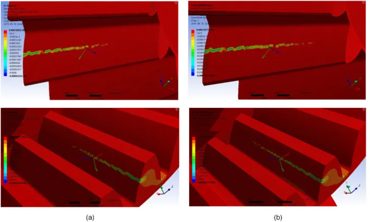
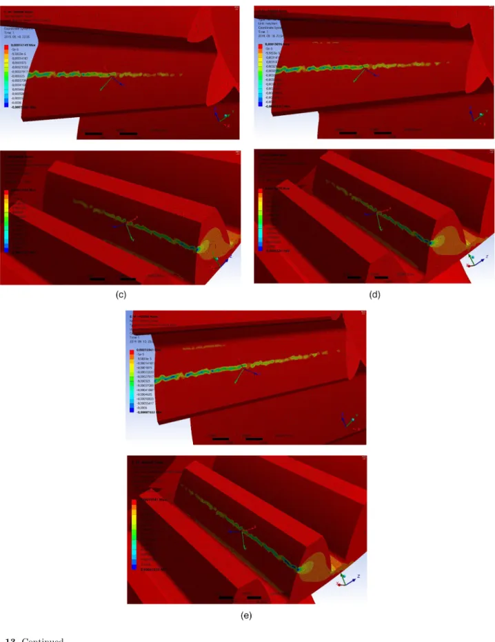
Based on the values of ex,ey,ezelastic strain per unit length and unit vectors related to them, the FE program calculates the normal direction resultant (en), which is perpendicular to the surface. As an effect of the loads on the surface of the driver and driven gear, normal elastic strain partitions and average normal elastic strain values occur (Fig. 13).
The results are shown in the diagram ofFigure 14. You can see that, in absolute value, as an effect of increasing loads, normal elastic strain values also increase on the tooth surfaces of the driver and driven gears.
The shapes of the two diagrams are the same and they are parallel. The normal elastic strains of the driven gear are a little higher than the normal elastic strains of the driver gear in absolute value. Because of the good comparison the same limits were set.
Fig. 11. Normal stress values. (a)M= 200 Nm: driver gear, sn¼ 2:054 MPa (top), driven gear,sn¼ 2:164 MPa (bottom).
(b)M= 250 Nm: driver gear,sn¼ 2:62MPa, driven gear,sn¼ 2:709MPa. (c)M= 300 Nm: driver gear,sn¼ 3:203MPa, driven gear,sn¼ 3:297MPa. (d)M= 350 Nm: driver gear,sn¼ 3:796MPa, driven gear,sn¼ 3:893MPa. (e)M= 400 Nm: driver gear, sn¼ 4:402MPa, driven gear,sn¼ 4:495MPa.
Fig. 11.Continued.
Fig. 12. Loadnormal stress diagram.
Fig. 13. Normal elastic strain values as a result of increasing loads. (a)M= 200 Nm: driver gear,en¼ 0.0000114 (top), driven gear, en¼ 0.0000127 (bottom). (b)M= 250 Nm: driver gear,en¼ 0.0000141, driven gear,en¼ 0.0000154. (c)M= 300 Nm: driver gear, en¼ 0.0000168, driven gear,en¼ 0.0000183. (d)M= 350 Nm: driver gear,en¼ 0.0000197, driven gear,en¼ 0.0000214. (e)M= 400 Nm: driver gear,en¼ 0.0000227, driven gear,en¼ 0.0000246.
Fig. 13.Continued.
4.5 Normal deformation analyses
As an effect of a load, the points of a solid body move, and the beginning state of the body differs from the state after full load application [22–24].
For instance, the position of an arbitrary P point of the body is given by the following placement vector, in the state before the load was applied [22–24]:
rP
! ¼xPe! þx yPe! þy zP!ez: ð27Þ Signals P0the state of P point after loading, the related placement vector is !rP ; the displacement vector is uP. Based onFigure 15you can state the following correlations [22–24]:
rP0
!¼r! þP !uP: ð28Þ The displacement vector is the function of the position of the points of the body before loading, i.e. the placement vector [22–24]:
! ¼u !u !r : ð29Þ The sum of the displacement vectors related to the points of the body is called displacementfield, where the displacement vector is [22–24]:
! ¼u uxe! þx uy! þey uze!z: ð30Þ
The coordinates of the displacement:
ux¼uxðx;y;zÞ uy¼uyðx;y;zÞ uz¼uzðx;y;zÞ
)
ð31Þ
As an effect of the different loads, on the tooth surfaces of the driver and driven gear, the following normal deformation values (in this case xdirection deformation) and average normal deformation values (the average of the xdirection values) occur (Fig. 16).
Fig. 14. Loadnormal elastic strain diagram.
Fig. 15. Definition of displacement vector.
Calculated results are shown inFigure 17. You can see that if the loads are increased the values of normal deformation also increase on the tooth surfaces of the driver and driven gear.
The shapes of the two diagrams are almost parallel. The normal deformations of the driver gear are higher than the normal deformations of the driven gear in absolute value.
The teeth are in contact that is why the presages of this specific are different. Because of the good comparison the same limits were set.
5 Conclusion
Straight bevel gears are widely used in machinery where the axes of the two shafts intersect, and the faces of the gears themselves form a cone. They are used as load transmission equipment, to change the number of rotation etc. Their further development (from construc- tional and technological point of view) and their LTCA based on different mechanical properties are highly needed.
Based on the geometrical and production analyses of the straight bevel gear pair, I developed a computer program to be able to design the drive pair. This program calculates all the geometrical parameters of the drive pair and draws the profile curves (which occur during production), on the smallest and largest diameters.
The given profile curves can be analyzed from constructional point of view and they are important for making our CAD model.
After that a CAM (Computer-Aided Manufacturing) software can be used to simulate the total production process of the drive pair.
It is important to have the CAD model for LTCA as well. These analyses are good for analyzing the mechanical properties on the driver and driven gear (such as stress, strains, elastic strain). LTCA are also important for having the appropriate constructional planning, to be able to choose the appropriate raw material, and to get important information about loads.
Normal stress, normal deformation and normal elastic strain values have been analyzed on the tooth surfaces of the driver and driven gear pair by different load torques. The results have been averaged, analyzed and shown in diagrams.
Fig. 16. Normal deformation values. (a)M= 200 Nm: driver gear,ux ¼ 0.0654 mm (top), driven gear,ux ¼0.00166 mm (bottom).
(b)M= 250 Nm: driver gear,ux¼ 0.0644 mm, driven gear,ux¼0.00207 mm. (c)M= 300 Nm: driver gear,ux¼ 0.0636 mm, driven gear,ux ¼0.00247 mm. (d)M= 350 Nm: driver gear,ux¼ 0.0629 mm, driven gear,ux ¼0.00286 mm. (e)M= 400 Nm: driver gear, ux ¼ 0.0621 mm, driven gear,ux¼0.00325 mm.
Fig. 16.Continued.
Nomenclature
!v 12 ð Þ
1R Relative velocity vector (mm/min1) n1R
! Normal vector of the surface in K1R coordinate system
r1R
! Placement vector of the moving
points of the profile curve r2R
! Placement vector of moving point of conjugated surface
rP
! Placement vector
rn
! Normal stress vector (MPa)
tn
! Shear stress vector (MPa)
!∇ Differential operator
M2R,1R,M1R,2R Translation matrices between K1R and K2Rcoordinate systems
P1k Matrix of kinematic mapping
c Root clearance factor
!u Displacement vector (mm)
sn Normal stress (MPa)
2⋅u Angle of planning (°)
A Deformation tensor
b Face width (mm)
d0 Largest pitch circle diameter (mm) df Largest tip circle diameter (mm) dl Largest root circle diameter (mm)
f0 Largest addendum (mm)
i21,i Transmission
js Clearance at flank (mm)
K1R(x1R, y1R, z1R) Rotational coordinate system related to the driver gear wheel
K1S(x1S, y1S, z1S) Static coordinate system related to the driver gear wheel
K2R(x2R, y2R, z2R) Rotational coordinate system related to the driven gear wheel
K2S(x2S, y2S, z2S) Static coordinate system related to the driven gear wheel
l0 Largest dedendum (mm)
m Module (mm)
M Load moment (Nm)
Re Effective pitch surface radius (mm) Sax Pitch circle face width on the largest
diameter (mm)
t Circular pitch on the largest pitch circle diameter (mm)
z1,z2 Number of teeth a0 Angle of contact (°)
d0 Pitch angle (°)
df Tip cone angle (°)
dl Root cone angle (°)
en Normal elastic strain (mm)
ex,ey,ez Elastic strain values per unit length (mm)
l Dedendum angle (°)
m Friction coefficient
S Shaft angle (°)
’ Addendum angle (°)
Fig. 17. Load–normal deformation diagram.
’1R,’2R Angular displacement (°)
E Distance between the vertex of cones (mm)
u, v, w Coordinates of the displacement vector (mm)
∂x∂;∂y∂;∂z∂ Parts of the differential operator gxy,gyx,gxz Shear specific elongation (mm) x, y, z Coordinates (mm)
This research was supported by the János Bolyai Research Scholarship of the Hungarian Academy of Sciences. The publication itself is partly supported by the EFOP-3.6.1-16- 2016-00022 project, and it is co-financed by the European Union and the European Social Fund.
References
[1] D.W. Dudley, Gear Handbook, MC Graw Hill Book Co., New York, 1962
[2] R. Gołe bski, A. Szarek, Diagnosis of the operational gear wheel wear, Technical Gazette26, 658–661 (2019) [3] J. Klingelnberg, Bevel Gear, Fundamentals and Applica-
tions, Springer, Berlin, 2016
[4] F.L. Litvin, A. Fuentes, Gear Geometry and Applied Theory, Cambridge University Press, Cambridge, 2004 [5] V. Rohonyi, Fogaskerékhajtások. Műszaki Könyvkiadó,
Budapest, 1980
[6] Z. Terplán, Gépelemek IV., Kézirat, Tankönyvkiadó, Budapest, 1975, p. 220
[7] J. Argyris, A. Fuentes, F.L. Litvin, Computerized integrated approach for design and stress analysis of spiral bevel gears, Comput. Methods Appl. Mech. Eng.191, 1057–1095 (2002) [8] I. Popa-Müller, Generation of eloid bevel-gear on tooth- cutting machine with the generating face-gear, 15th International Conference in Mechanical Engeneering, Cluj- Napoca, 2007
[9] F.L. Litvin, Gear geometry and applied theory, Prentice Hall, Englewood Cliffs, NJ, 1994
[10] A. Fuentes, J.L. Iserte, I. Gonzalez-Perez, F.T. Sanchez- Marin, Computerized design of advanced straight and skew bevel gears produced by precision forging, Comput. Methods Appl. Mech. Eng.200, 2363–2377 (2011)
[11] I. Juhász, Görbékés felületek modellezése, Miskolci Egyetem, elektronikus jegyzet, p. 114
[12] Z. Fangyan, Z. Mingde, Z. Weiqing, T. Rulong, G. Xiaodong, On the deformed tooth contact analysis for forged bevel gear modification, Mech. Mach. Theory135, 192–207 (2019) [13] G.D. Bibel, A. Kumar, S. Reddy, R. Handschuh, Contact
stress analysis of spiral bevel gears using finite element analysis, J. Mech. Des117, 235–240 (1995)
[14] F.L. Litvin, A. Fuentes, I. Gonzales-Perez, L. Carnevali, T.M. Sep, New version of Novikov-Wildhaber helical gears:
computerized design, simulation of meshing and stress analysis, Comput. Methods Appl. Mech. Eng. 191, 5707–
5740 (2002)
[15] F.L. Litvin, A. Fuentes, I. Gonzalez-Perez, L. Carvenali, K.
Kawasaki, R.F. Handschuh, Modified involute helical gears:
computerized design, simulation of meshing and stress analysis, Comput. Methods Appl. Mech. Eng. 192, 3619– 3655 (2003)
[16] S. Peng, H. Ding, G. Zhang, J. Tang, Y. Tang, New determination to loaded transmission error of the spiral bevel gear considering multiple elastic deformation evaluations under different bearing supports, Mech. Mach. Theory137, 37–52 (2019)
[17] I. Popa-Müller, Case-study and simulation by meshing of bevel-gears, 14th International Conference in Mechanical Engeneering, Tg-Mures, 2006
[18] I. Popa-Müller, Simulation of Generation by Meshing of Conical Gear Octoid II with Hobbing Machine Heidenreich- Harbeck, 18th International Conference in Mechanical Engeneering, Baia Mare, 2010
[19] J.K. Theodore, Tooth contact analysis of spiral bevel and hypoid gears under load, SAE Trans. 90, 2205–2216 (1981)
[20] H. Zehua, D. Han, P. Shandong, T. Yi, T. Jinyuan, Numerical determination to loaded tooth contact perfor- mances in consideration of misalignment for the spiral bevel gears, Mech. Mach. Theory151, 343–355 (2019)
[21] W. Wagner, S. Schumann, B. Schlecht, Co-simulation of the Tooth Contact of Bevel Gears within a Multibody Simula- tion, Forsch Ingenieurwes83, 425–433 (2019)
[22] I. Kozák, Gy. Szeidl, Fejezetek a szilárdságtanból, Kézirat, 2008–2012, Miskolci Egyetem, p. 284. elektronikus jegyzet [23] S. Moaveni, Finite Element Analysis, Theory and Applica-
tion with ANSYS, Pearson Education Limited, London, 2015, p. 928
[24] I. Páczelt, T. Szabó, A. Baksa, A végeselem módszer alapjai, Miskolci Egyetem, p. 243
Cite this article as: S. Bodzás, Computer-aided design and loaded tooth contact analyses of bevel gear pair having straight teeth by different loaded torques, Mechanics & Industry21, 109 (2020)
![Fig. 3. Heidenreich – Harbeck principle [6].](https://thumb-eu.123doks.com/thumbv2/9dokorg/773266.34769/2.892.93.418.93.389/fig-heidenreich-harbeck-principle.webp)