Tunnel-excavation-induced permeability change of rock mass around a radioactive waste
repository tunnel
Dániel Borbély*
Department of Engineering Geology and Geotechnics, Budapest University of Technology and Economics, Budapest, Hungary
Received: August 1, 2017; accepted: December 3, 2017
Upon completion, the National Radioactive Waste Repository in Bátaapáti will provide safe storage for low- and medium-level radioactive waste. The emplacement chambers were excavated in a fractured, blocky, granitic rock mass approximately 240 m below surface. One of the tasks related to the repository development is the feasibility demonstration of the permanent repository closure, including long-term rock mass associated issues. The required lifetime exceeds the usual one of an engineering structure. The long- term behavior of the repository needs to be extrapolated from observation over a shorter time period, or from analogous natural caverns. Numerical methods are the most promising techniques to carry out the extrapolation. It is commonly understood that there are significant uncertainties in long-term predictions.
Uncertainties can be mitigated by utilizing independent methods to assess long-term behavior and by improving the prediction capability of the calculation model in the short term. The aim of the paper is to:
(1) create a numerical model to effectively capture a wide range of the observed behavior of the rock mass, including tunnel-excavation-induced stress change and stress-dependent permeability and (2) identify the possible cause of long-term creep and show that the long-term creep can be captured by the selected calculation method. The moderately fractured rock mass is modeled using the Universal Distinct Element Code, released by Itasca. The joints in the rock mass are explicitly modeled; the blocky nature of the rock mass is captured. The model is verified with actualfield observations and monitoring results. Based on the predicted stress state of the rock mass, the potential cause of long-term creep is identified. By fulfilling the
*Corresponding address: Department of Engineering Geology and Geotechnics, Budapest University of Technology and Economics, Muegyetem rkp. 3., Budapest H-1111, Hungary
E-mail:daniborbely@gmail.com
This is an open-access article distributed under the terms of theCreative Commons Attribution-NonCommercial 4.0 International License, which permits unrestricted use, distribution, and reproduction in any medium for non- commercial purposes, provided the original author and source are credited, a link to the CC License is provided, and changes–if any–are indicated.
DOI: 10.1556/24.61.2018.05 First published online March 9, 2018
two aims explained above, it is concluded that the model can be used to extrapolate in time and serve as a possible estimation method for the long-term behavior of the repository.
Keywords:excavation disturbed zone, monitoring, permeability, radioactive waste repository, tunnel
Introduction
Rock engineers need to extrapolate small-scale, short-term lab test results to the actual extent and time scale of the project. In rock engineering practice, three main methods are used: empirical, analytical, and numerical methods.
In cases where a sufficient amount of previous experience is available, empirical methods can be used. The most widely used methods are the Terzaghi’s rock load theory (Terzaghi 1946), the rock mass rating (RMR) introduced by Barton et al. (1974) and Bieniawski (1976), and the tunnelling quality index (Q), and geological strength index (GSI) introduced by Hoek (1994).
In cases where joint properties, intact rock properties, and scale effect are known, analytical tools can be used. Analytical relationships can be derived for the elastic moduli of the fractured rock mass (Lekhnitskii 1977;Oda 1982).
In recent years, numerical modeling, the synthetic rock mass approach (Ivars et al.
2011), is a viable option to determine large-scale or long-term rock mass properties (Vallejos et al. 2013). It takes stochastically discrete fracture networks, and complex intact rock properties, such as brittle failure, under consideration. The extrapolation of coupled hydromechanical properties was investigated by Min et al. (2004).
The required lifetime of the engineering barriers is considerably greater than the usual lifetime of an engineering structure. The long-term behavior of the repository needs to be extrapolated from observation over a shorter time period (decades). In the case of the lack of previous experience, geo-mathematical methods and numerical models are the most promising techniques to carry out the extrapolation.
The aim of this paper is to set up a reasonable estimation of the construction events, compare model behavior to the observed behavior of the actual rock mass, and to identify the cause/source of the time-dependent displacements measured on site (Kovács et al. 2013).
Materials and methods
Typical rock support
This investigation was based on the measurements carried out in the National Radioactive Waste Repository (NRWR). The facility is located in Bátaapáti, southwestern Hungary, in the Mecsek Mountains. The I-K1 emplacement chamber is investigated here. This chamber was driven through a range of Q-system-based rock support classes. For the assessment of long-term behavior, rock class 2b (moderately fractured rock mass) was considered to be characteristic in this case.
The rock support system consists of 120-mm steelfiber-reinforced sprayed concrete lining with systematic 4-m-long rock bolting in a 1.5×1.5 m raster (Fig. 1).
The I-K1 emplacement chamber was driven in two drifts with drill and blast technique in about 100-m length. The diameter of the equivalent area circular chamber is about 11 m.
Rock mechanical characterization of surrounding ground
Intact rock properties.The rock mass is composed of porphyritic monzogranite along with darker and morefine-grained, equigranular monzonitic, and lighter aplitic rocks (Balla 2004). The results of systematic rock sampling are presented in the study by Kovács et al. (2012) and summarized in Table1. According to Damjanac and Fairhurst (2010), intact rock creep does not occur below the crack initiation limit. Considering minor cracks in the blocks, properties are calculated using the Hoek–Brown failure criteria assuming that the GSI value is equal to 85.
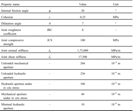
Joint properties.The behavior of jointed rock mass (or an associated distinct element model) highly depends on the joint characteristics (Table 2). The shear
Fig. 1
Right: rock support (Benkovics et al. 2010) and left: backfill option (Kovács et al. 2010)
Table 1
Intact rock properties
Property name Value Unit
Uniaxial compressive strength UCS 129 MPa
Crack initiation limit σci 34.3 MPa
Hoek–Brown parameter mi 15 –
Disturbance factor D 0 –
Young’s modulus E 67,000 MPa
Poisson’s ratio 0.232 –
Unit weight γ 0.027 MPa/m3
Table 2 Joint properties
Property name Value Unit
Internal friction angle φ 30 °
Cohesion c 0.25 MPa
Dilatation angle δ 7 °
Joint roughness coefficient
JRC 8 –
Joint compressive strength
JCS 100 MPa
Joint normal stiffness Jn 1,75,000 MPa/m
Joint shear stiffness Js 17,500 MPa/m
Unloaded mechanical aperture
– 266 10–6m
Unloaded hydraulic aperture
– 236 10–6m
Hydraulic aperture under in situstress
– 106 10–6m
Mechanical aperture underin situstress
– 44 10–6m
Minimal hydraulic aperture
– 10 10–6m
strength of the joints had been measured by laboratory tests (Buocz et al. 2010,2017) and was verified by plain strain distinct element models (Horváth et al. 2012).
Joint pattern.During excavation, a systematic face mapping program was per- formed, and the Q, GSI, and RMR values were all determined. Detailed discussion on geotechnical rock mass documentation is presented by Deák et al. (2014).
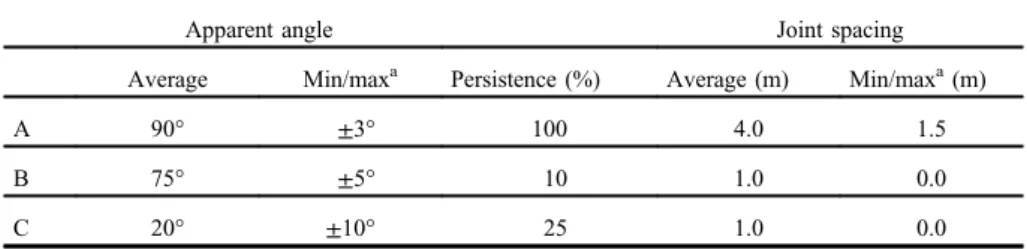
The direction and spacing of the main joint set shows a good match with Kovács et al. (2012). The joint directions listed in Table 3 follow approximately the same distribution as the actual joints. The persistence and trace length of the joints were estimated according to the work of Zhang and Einstein (2000), based on the number of joints with different end conditions on a face and the area of tunnel face. Since the joint pattern is scale-independent (Hobbes 1993), the persistence in the model was compared with the fault zones and major fractures on the geologic map of the area (Balla 2004), to verify the joint pattern. The joint patterns selected to characterize the rock mass are shown in Fig.2.
In situ tests
An often-used method of instrumental monitoring in Bátaapáti is the mechanical convergence measurement that represents a reliable method, for an affordable price, for ground deformation monitoring. Convergence measurement resulting from 14 arrays is considered in this paper. Details on convergence monitoring arrays were reported by Kovács et al. (2012). Measured convergence from various part of the repository was correlated with the Q and RMR systems by Kovács et al. (2012).
The correlated displacements are considered to be an average displacement represen- tative for a tunnel driven in a rock mass with given RMR or Q value.
To better understand the rock mass behavior and to be able to optimize the pillar width between two chambers, the stress change during chamber excavation was measured. Commonwealth Scientific and Industrial Research Organisation (CSIRO) cells were used to measure stress change in the rock. Boreholes were drilled from the tunnel, near parallel with the tunnel axis. The CSIRO cells were installed in the
Table 3 Joint directions
Apparent angle Joint spacing
Average Min/maxa Persistence (%) Average (m) Min/maxa(m)
A 90° ±3° 100 4.0 1.5
B 75° ±5° 10 1.0 0.0
C 20° ±10° 25 1.0 0.0
aLimit for uniform distribution
boreholes in front of the advancing face to capture the entire stress path. Further detail on preparation, installation, operation, data processing, and results can be found in the study by Kovács and Mészáros (2011).
The inelastic deformation in rock masses is usually coupled with acoustic emission (AE) events. To monitor the inelastic deformations, an AE monitoring system was installed around the chambers (Szucs and Bakai 2012). The AE events are shown in˝ Fig.3.
Fig. 3
(a) Locations of AE events in the model, cross section of the emplacement chamber and (b) locations of AE events measured on site, plan view of the emplacement chamber
Fig. 2
(a) Actual face mapping: black outline represents tunnel diameter–6.9 m and (b) modeled joint pattern: red ellipse represents approximately the same area as the actual tunnel. Vertical and horizontal scales are the same for bothfigures, units are in meters
The rock mass hydraulic conductivity was determined byfield test. Thefield tests were verified with numerical modeling (Mezo 2009). According to the˝ field measure- ments, the hydraulic conductivity of the rock mass is between 1.0×10⁻¹² and 1.0×10⁻⁶m/s, average is 2×10⁻⁹m/s.
Numerical model
The two-dimensional Universal Distinct Element Code (UDEC) 5.0 was applied in the numerical modeling. To appropriately represent the stress path and block movement induced by the chamber excavation, the following main modeling stages were considered:
1. Set up thein situcondition. The horizontal stress ratio is 1.4 at the tunnel axis and 1.2 along the tunnel axis (Kovács et al. 2012).
2. The tunnel is excavated in one go. The three-dimensional redistribution of the stresses was considered with a relaxation factor of 30%.
3. Rock support installation: the aging of the sprayed concrete lining was considered in the model, according to the study by Chang and Stille (1993).
Results and discussion
Displacements
As presented in Kovács et al. (2012), rock mass stiffness was determined using rock mass classification and was validated with convergence monitoring. The displacements in the UDEC model were compared with a continuumfinite-element model generated by Phase2. The displacements are in good agreement, i.e., 2.0–3.6 and 2.6–3.4 mm in the UDEC model (Fig.4) and in the Phase2 model, respectively.
Stress redistribution
An anomaly in stress change that cannot be explained by continuum representation of the rock mass was observed on site. This anomaly in stress change can be observed in the UDEC model as well. Field stress-induced wedge movement occurs in contact with the rock mass is partially lost (or at least inelastic displacement form), and both horizontal and vertical internal stresses of the block decrease significantly (Fig.5).
The results of the field measurement, the UDEC model, an elastic continuous Phase2 model, and a continuous brittle-plastic Phase2 model are compared in Fig.6.
The UDEC model shows good agreement with thefield measurements, but this is not the case with the continuous models. The size of the moving wedge on site might differ from the modeled one; the wedges on site are tetrahedrons, instead of the modeled triangular prisms, but it can be concluded that the general phenomenon itself is well captured in the model.
AE monitoring
According to Damjanac and Fairhurst (2010), AE does not initiate in the intact rock if it is loaded under the crack initiation limit. The difference between the major and minor principal stresses is below 23.5 MPa in 100% of the zones and 15 MPa in 99.75% of the zones. Crack initiation of the intact rock occurs around 34 MPa, so the stresses are significantly below the crack initiation limit of the intact rock. According to these results, it can be concluded that the AE events are caused by the slips of the joints. The assumed AE activity in the model (approximately 9–10 m; Fig.3a) is in good agreement with thefield observations (approximately 10–12 m; Fig.3b).
Hydraulic conductivity
The equivalent hydraulic conductivity of the rock mass (considered in the UDEC model) was calculated using the crack tensor (Oda 1985). The hydraulic conductivity of an individual joint was determined according to Barton et al. (1985). The hydraulic conductivity of the rock mass considered in the UDEC model is 1.76×10⁻⁸m/s. The average hydraulic conductivity of the actual rock mass is 2×10⁻⁹m/s (Mezo 2009).˝
Fig. 4
Predicted displacement in the UDEC
Fig. 5
Predicted horizontal stress in the UDEC
Fig. 6
Predicted and measured stress change at the top heading
There is one order of magnitude difference in the modeled and measured hydraulic conductivities.
The hydraulic conductivity of each joint has been calculated according to Oda (1985). The aperture change during the excavation was directly calculated by a tailor- made solution built in the distinct element code. The hydraulic conductivity of an individual joint is plotted in Fig. 7. As can be seen, the hydraulic conductivity increases in the vicinity of the tunnel. At the stage of rock-support system installation, the radius of the disturbed zone is within the extent of two tunnel radii, measured from the chamber axis (Fig. 7).
It has been noted that the model overestimates the change in hydraulic conductivity induced by tunneling. However, the predicted tendencies are believed to be a faithful representation of the phenomenon and a promising method to compare backfilling options.
Conclusions
The results are significant because models are a starting point for the extrapolation for further long-term investigations. The cause and source of the time-dependent displace- ments are identified. Based on the research presented here, joint creep is the primary source of long-term displacements. Next steps for this research are to carry out joint-creep tests and implement creep modeling to a numerical model. The modeling results can then be compared with the experience gained in thefirst few years (Kovács et al. 2013).
Fig. 7
(a) Decimal logarithm of joint hydraulic conductivity (m/s) of an individual joint and (b) equivalent conductivity of the rock mass
The inherent uncertainty of long-term predictions can be reduced using indepen- dent methods, with various assumptions. This research is aimed to be one of the several valid methods.
Acknowledgements
The author would like to express his gratitude to RHK Ltd. for granting permission to collect and use data related to the NRWR project.
References
Balla, Z. 2004: General characteristics of the Bátaapáti (Üveghuta) Site (South-western Hungary).–Annual Report of the Geological Institute of Hungary, 2003, pp. 73–85.
Barton, N., R. Lien, J. Lunde 1974: Engineering classification of rock masses for the design of tunnel support.–Rock Mechanics, 6/4, pp. 189–236.
Barton, N., S. Bandis, K. Bakhtar 1985: Strength, deformation and conductivity coupling of rock joints.– International Journal of Rock Mechanics and Mining Sciences, 22/3, pp. 121–140.
Benkovics, I., K. Barabás-Rebr´o, J. Berta, J. Csicsák, Z. Hogyor, F. Kerek, L. Ropoli, G. Szebényi, P.
Tamás, P. T´oth, M. Varga, V.R. Miskolczi, F. Vrászlai, F. Takáts, L. Kulcsár, A. Thomas, D. Hersvik, T.
Megyeri, Gy. Németh, A. Lowson 2010: A Bátaapáti Nemzeti Radioaktívhulladék-tárol´o feltár´o vágatai térkiképzése. Kiviteli terv, II. ütem, 3. Szakasz, I-K1 és I-K2 tárol´okamra [Bátaapáti National Radioactive Waste Repository excavation of the access tunnels. Design plan, Stage 2, Section 3, Repository chambers 1-K1 and 1-K2].–Manuscript, RHK Kft., Pécs, RHK-K-123C/09. (in Hungarian) Bieniawski, Z.T. 1976: Rock mass classification in rock engineering. – In: Bieniawski, Z.T. (Ed):
Symposium Proceedings of Exploration for Rock Engineering, Balkema, Cape Town, pp. 97–106.
Buocz, I., N. Rozgonyi-Boissinot, P. Görög, Á. Török 2010: Laboratory determination of direct shear strength of granitoid rocks; examples from the host rock of the nuclear waste storage facility of Bátaapáti (Hungary).–Central European Geology, 53/4, pp. 405–417.
Buocz, I., N. Rozgonyi-Boissinot, Á. Török 2017: The angle between the sample surface and the shear plane: Its influence on the direct shear strength of jointed granitic rocks and Opalinus claystone.– Procedia Engineering, 191, pp. 1008–1014.
Chang, Y., H. Stille 1993: Influence of early age properties of shotcrete on tunnel construction sequences.– In: Wood, D.F., D.R. Morgan (Eds): Shotcrete for Underground Support VI. American Society of Civil Engineers, New York, pp. 110–117.
Damjanac, B., C. Fairhurst 2010: Evidence for a long-term strength threshold in crystalline rock.–Rock Mechanics and Rock Engineering, 43/5, pp. 513–531.
Deák, F., L. Kovács, B. Vásárhelyi 2014: Geotechnical rock mass documentation in the Bátaapáti Radioactive Waste Repository.–Central European Geology, 57/2, pp. 197–211.
Hobbes, B. 1993: Significance of structural geology in rock mechanics. – In: Brown, E.T. (Ed):
Comprehensive Rock Engineering–Fundamentals. Pergamon Press, Oxford, pp. 25–62.
Hoek, E. 1994: Strength of rock and rock masses.–ISRM News Journal, 2/2, pp. 4–16.
Horváth, Zs., T. Megyeri, Á. Vár´o, P. Görög 2012: Discrete element modelling of the M´orágy Granite Formation in Southern Hungary.–In: Horváth, T. (Ed): 1st Eastern European Tunneling Conference.
Magyar Alagútépíto Egyesület, Budapest, Paper 22.˝
Ivars, D.M., M.E. Pierce, C. Darcel, J. Reyes-Montes, D.O. Potyondy, R.P. Young, P.A. Cundall 2011:
The synthetic rock mass approach for jointed rock mass modelling.–International Journal of Rock Mechanics and Mining Sciences, 48/2, pp. 219–244.
Kovács, L., E. Mészáros 2011: Jelentés a térkiképzés okozta kozetfeszültség-változás CSIRO HI-cellás mérési˝ programjár´ol; Bkc-7, : : :, Bkc-12 [Report on the CSIRO HI-cell measuring program of stress change caused by tunnel excavation; Bkc-7, : : :, Bkc-12].– Manuscript, RHK Kft., Paks, RHK-K-077/11.
(in Hungarian)
Kovács, B., Z. Bothi, P. Molnár, Gy. Dank´o 2010: Lezárási koncepci´o fejlesztése [Final sealing of the˝ radioactive waste repository, conceptional design].–Manuscript, RHK Kft., Paks, RHK-K-093/09.
(in Hungarian)
Kovács, L., F. Deák, G. Somodi, E. Mészáros, K. Máté, A. Jakab, B. Vásárhelyi, J. Geiger, Gy. Dank´o, F.
Korpai, Gy. Mezo, K. Darvas, P. Ván, T. Fülöp, Cs. Asszonyi 2012: A Geotechnikai értelmez˝ o jelentés˝ (GÉJ) felülvizsgálata és kiterjesztése [Updated version of the Geotechnical Investigation Report].– Manuscript, RHK Kft., Pécs, RHK-K-032/12. (in Hungarian)
Kovács, L., E. Mészáros, F. Deák, G. Somodi 2013: Idofügg˝ o deformáci´os jelenségek a Bátaapáti NRHT˝ térségeiben és azok lehetséges okai [Time-dependent deformations in the underground openings of NRWR at Bátaapáti and their possible causes].– In: Török, Á., P. Görög, B. Vásárhelyi (Eds):
Mérnökgeol´ogia–Kozetmechanika 2013 [Engineering Geology˝ –Rock Mechanics 2013]. Hantken Kiad´o, Budapest, pp. 177–194. (in Hungarian)
Lekhnitskii, S.G. 1977: Theory of elasticity of an anisotropic body.–Mir Publishers, Moscow, 430 p.
Mezo, Gy. 2009: Az els˝ o két kamra engedélyeztetését megalapoz´o vízföldtani modell [Hydrogeologic˝ modeling, FeFlow model].–Manuscript, RHK Kft., Paks, RHK-K-158/09. (in Hungarian) Min, K., J. Rutqvist, C. Tsang, L. Jing 2004: Stress-dependent permeability of fractured rock masses:
A numerical study.–International Journal of Rock Mechanics and Mining Sciences, 41/7, pp. 1191–1210.
Oda, M. 1982: Fabric tensor for discontinuous geological materials.–Soils and Foundations, 22/4, pp. 96–108.
Oda, M. 1985: Permeability tensor for discontinuous rock masses.–Géotechnique, 35/4, pp. 483–495.
Szucs, I., J. Bakai 2012: A Bátaapáti 1˝ –2 tárol´okamra környezetének szeizmoakusztikus monitoring rendszere [Seimoacoustic monitoring system in the environs of the 1st and 2nd chambers of Bátaapáti repository].–In: Sámson, M., G. Hámos (Eds): A Nemzeti Radioaktívhulladék-tárol´o (NRHT) elso két˝ kamrája kialakításának földtudományi, bányászati és technol´ogiai eredményei [Geoscientific, mining and technological results of the construction of the 1st and 2nd chambers of the National Radioactive Waste Repository]. Molnár Nyomda és Kiad´o, Pécs, pp. 81–85. (in Hungarian)
Terzaghi, K. 1946: Rock defects and loads on tunnel supports.–In: Proctor, R.V., T.L. White (Eds): Rock Tunneling with Steel Supports. Commercial Shearing and Stamping Company, Youngstown, pp. 17–99.
Vallejos, J.A., A. Brzovic, C. Lopez, L. Bouzeran, D. Mas Ivars 2013: Application of the Synthetic Rock Mass approach to characterize rock mass behavior at the El Teniente Mine, Chile.–Proceedings of the 3rd International FLAC/DEM Symposium, Minneapolis, pp. 1–15.
Zhang, L., H. Einstein 2000: Estimating the intensity of rock discontinuities.–International Journal of Rock Mechanics and Mining Sciences, 37/5, pp. 819–837.