Scattering, injection and acceleration of field aligned beam ions at quasi-parallel shock: a hybrid simulation
study
Arpad Kis, Lemperger Istvan, Voros Zoltan, Szalay Sandor
Research Centre for Astronomy and Earth Sciences, Geodetic and Geophysical Institute, 9400 Sopron, Csatkai u. 6-8, Hungary
Shuichi Matsukiyo
Faculty of Engineering Sciences, Kyushu University, Kasuga, Fukuoka, Japan
Abstract
The process of injection into the first-order Fermi acceleration, also called dif- fusive shock acceleration or DSA, at quasi-parallel shocks is still not completely understood. In our analysis we study the scattering and the aceleration of field aligned beam ions in the foreshock region of a quasi-parallel shock by using a 1D hybrid simulation setup. Test particles are introduced into the simulation box in a developed foreshock wave field and these particles are followed until the end of the experiment. Our results show that more than 40% of the original FAB ions reach the shock and become accelerated to energies that are typical of diffuse ions.
Keywords: collisionless plasma, diffusive shock acceleration, ion injection
1. Introduction
Energetic ions with energies above solar wind ion energies upstream of the Earth’s bow shock were subject to many investigations since their early reports by Asbridge et al. [1] and by Lin et al. [7]. Studies demonstrated that these energetic ions have two different sources, so they can be divided into energetic
5
ions of magnetospheric origin [10, 9] and bow shock related ions. Bow shock
Preprint submitted to Journal of High Energy Density Physics, HEDLA ProceedingsNovember 29, 2018
related ions are those that are reflected or accelerated by the Earth’s bow shock [3].
According to the value of the ΘBn angle between the shock normal and the upstream magnetic field direction shocks can be classified as quasi-perpendicular
10
(ΘBn>45◦) or quasi-parallel (ΘBn<45◦).
Ions associated to the quasi-perpendicular side of the Earth’s bow shock show characteristics of a more beam-like distribution in velocity space. They are streaming away from the bow shock and move against the incoming solar wind along the upstream magnetic field lines [8].
15
Kis et al. [6] demonstrated that this beam-like distribution of the so-called FAB ions can evolve first into an intermediate, and later into a toroidally gy- rating ion distribution. The toroidally gyrating ions can be found deeper in the foreshock region as a consequence of interaction with self-induced waves and convection by the solar wind.
20
Originally it was proposed that the ions forming the field-aligned beam (from now on: FAB) might provide the principal seed population for the diffusive ion acceleration mechanism. Ipavich et al.[4] demonstrated that the He/H ratio of energetic ions at about 30 keV in the upstream region is highly correlated with He/H ratio in the solar wind. At the same time, the He to H density ratio in the
25
field-aligned beams is dramatically smaller than that measured simultaneously in the solar wind (see Ipavich et al. [5] and Fuselier & Thomsen [2]). These results suggested that the solar wind ions, and not the FAB ions are the primary source for the diffuse ions.
In this paper we analyse the spatio-temporal evolution of the field-aligned
30
beam ions in front of the quasi-parallel shock by using test particles in a hybrid simulation. In addition we explore the conditions and possibility of these FAB ions to be injected into and accelerated by the first-order Fermi acceleration process. The simulation is based on the shock parameters and energetic ion data recorded by Cluster SC on 18 February, 2003, during a high Mach number
35
shock event. This event is described in detail byKis et al.[6].
2. Simulation
The parameters of the simulation were set to provide a shock with MA ∼ 8 and ΘBN ∼ 20◦, similar to the values of the shock observed by Cluster on 18 February, 2003. The simulation domain consists of 5000 cells inxdirection,
40
each cell has a dimension of 0.5 λi. In real space one ion inertial length cor- responds to ∼144 kilometers in our case, or in other words ∼ 44 ion inertial lengths are equivalent to 1 Re. The initial system consists of 800000 particles.
This corresponds to∼160 particles per cell. At each timestep a number of par- ticles are injected at the left-hand side (LHS) of the system with a velocity of
45
v=6.15vA, modelling the solar wind (note that all the velocities are normalized to the Alfv´en velocity). The right-hand side (RHS) of the system is a rigid wall.
All the particles reaching the RHS are reflected. The reflected particles interact with the incoming ”solar wind” particles through a self-consistent electromag- netic field resulting in a shock wave. The shock wave moves in the negative
50
direction (i.e. towards the LHS) with a velocity of∼-1.86 vA, which results in a shock velocity equivalent to∼8 MA relative to the incoming particles. The LHS of the simulation domain is a free-escape boundary: each particle reaching the LHS is eliminated from the system. The simulation run time has been set to 675 Ω−ci1. During a test run, it was determined that after ∼ 337 Ω−ci1 the
55
low frequency electromagnetic waves are fully developed on the left side to the shock wave, i.e. in the upstream region. Figure 1 shows the magnetic field in the simulation box at 337 Ω−ci1after the beginning of the simulation. The shock at this time is located atx∼1800λi.
3. Discussion and Results
60
The purpose of the simulation was to investigate how an ion beam evolves in the upstream magnetic wave field. Therefore we examine the distribution of beam ions at different distances from the shock. The field-aligned beam in real space consists of reflected ions at the quasi-perpendicular side of the bow shock.
These ions travel into the upstream direction along the magnetic field with a
65
3
0 500 1000 1500 2000 2500
−4
−2 0 2 4 6
upstream LHS
test particle release point
RHS shock position
Magn. field By component
X position (ion inertial lenght)
downstream
Figure 1: The panel shows the magnetic field By component after 6750 timesteps from the beginning of the simulation, when the test particles has been released in the region in front of the shock.
velocity of approximately twice the solar wind bulk velocity. Because the mag- netic field is convected by the solar wind, the FAB ions are also convected into the foreshock region (i.e., to the quasi-parallel side of the shock). To simulate the appearance of FAB ions upstream of the quasi-parallel shock, additional test particles were introduced in the simulation box with velocities characteristic of
70
field-aligned beam ions. As mentioned before, at t=337 Ω−ci1, the shock and the upstream magnetic wave field was developed in a self-consistent way. At this time 12000 test particles have been released atx∼1400λiin front of the shock, which is equivalent to∼7 Re distance from the shock in real space. The test particles were released with a velocity of∼-12.7vAparallel to the magnetic field
75
in the upstream direction. (In the following we will refer to test particles as beam particles.)
The beam particles were followed after their release until the end of the simulation. The beam particles were also used to study how many of these particles move downstream and what is the percentage of particles involved
80
in Fermi-acceleration at the shock; i.e. the effectiveness of Fermi-acceleration related to these particles.
Figure 2 shows the distribution of beam particles inv⊥−v∥velocity space at different distances from the shock after 337 Ω−ci1from their release. At this time the shock was atx∼1500λi. The foreshock region was divided into intervals
85
of 250 λi. The panels show the distributions of the beam particles found in the respective interval. In every panel the particles are scattered in pitch angle along a circle. However, the amount of scattering differs substantially in each panel. The less scattered population is the farthest from the shock. Here all the particles have negativev∥ values (i.e., they move towards the LHS boundary).
90
As the distance to the shock decreases, the scattering becomes larger. In front of the shock the particles form an almost complete circle or narrow shell.
Especially in panel F, but also on panel E we can observe particles outside the scattering circle, most of them moving in the upstream direction. These are particles which have already reached the shock, were accelerated at the shock
95
and backscattered into the upstream region.
5
Note that on panel F among the particles situated on the circle, more par- ticles have pitch angles close to 90 degree, and fewer have pitch angles close to zero. This shows the limitations of the quasilinear theory since it is assumed that every particle is scattered the same way irrespective of their pitch angle;
100
in which case the distribution of particles over the scattering circe would be more isotropic. In order to describe more precisely the scattering process of the particles by waves an improved model is needed. These results show that the scattering efficiency over pitch angle might be a function of the pitch angle itself. This effect can be observed in every panel in Figure 2; however it is more
105
obvious closer to the shock, where the magnetic wave energy is higher.
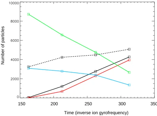
Figure 3 presents the beam particle number evolution over time in the differ- ent regions of the simulation domain. The released beam particles are scattered in pitch angle by the already existing waves. The scattering in velocity space also leads to scattering in real space, since the particles can move away from the
110
shock or they can move closer to it, depending on their parallel velocity. When the beam particles reach the shock they can be accelerated and scattered back into the upstream region or they can travel downstream. Those particles which travel deep into the downstream region have a very small probability to reenter into the upstream region because of the high amplitude magnetic turbulance in
115
the shocked downstream region; an obstacle which is very difficult to overcome.
Therefore the particles need to stay close to the shock on the downstream side, or in other words they need to be efficiently scattered in pitch-angle in order to reenter into the upstream region.
Particles accelerated and backscattered into the upstream region are again
120
subject to scattering by waves and might be backscattered again to the shock where they can continue to move downstream or they can be injected into an- other acceleration process. The accelerated particles, especially particles with higher velocities, can propagate far from the shock into the upstream region and eventually might escape the system on the LHS of the simulation domain.
125
To summarize, the beam particles can:
V parallel
V perpendicular V perpendicular
V parallel
V parallel
V perpendicular V perpendicular
V parallel
V parallel
V perpendicular V perpendicular
V parallel
A B
C D
E F
Figure 2: The beam particle distributions at different distances from the shock after 337.5 Ω−ci1from the release of beam particles in the upstream region. The letter A denotes the 0-250 λiinterval, the farthest from the shock, while the letter F denotes the 1250-1500λiinterval, the region just in front of the shock; all the other letters are denoting succesively the other
intervals. 7
150 200 250 300 350 Time (inverse ion gyrofrequency)
Number of particles
Figure 3: The graph presents the evolution of the particle number versus time. The colour refers to test particles with initial velocity located upstream (green), accelerated upstream (blue), downstream convected (bashed black), escaped on the LHS (black), and finally particles accelerated and escaped on the LHS (red). The unit of time is the timestep of the simulation, i.e. 0.05 inverse ion gyrofrequency (Ωci). The zero value of time marks the moment when the test particles has been released.
1. leave the system on the LHS without being accelerated, i.e. without get- ting in contact with the shock
2. move downstream after crossing the shock
3. become accelerated at the shock and backscattered into the upstream
130
region (these particles will have higher energies than before meeting the shock)
4. become accelerated at the shock, move far away from it into the region with small magnetic fluctuations and leave the system at the LHS The advantage of such a simulation is that the beam particles can be fol-
135
lowed in time, which provides the possibility to investigate the details of their behaviour. In data provided by spacecraft, the origin of the different ion popula- tions cannot be determined through direct observation. Figure 3 shows that the total number of beam particles found in the upstream region decreases almost linearly with time together with beam particles which have been accelerated
140
at the shock. On the other hand, the number of beam particles which moved downstream increases together with particles which have already left the system on the LHS. The LHS of the simulation domain is a free-escape boundary, beam particles reaching this far from the shock are removed from the system.
Figure 3 demonstrates the ratio of test particles found in different regions
145
of the simulation box. After a time period of∼312 Ω−ci1 ∼42 % of the 12000 initially upstream-released beam particles have already moved downstream, ∼ 22 % are to be found still in the upstream region, while ∼35 % have left the system on the LHS. Taking into account only those particles which have been accelerated to a velocity of at least∼ 18.2 vA (corresponding to the velocity
150
of a 10 keV diffuse ion on spacecraft data) and which have escaped or are in the upstream region, we conclude that∼44 % of the beam particles have been accelerated at the shock and escaped the shock in the upstream direction.
In other words, based on the simulation result,∼44 % of the original field- aligned beam ions become diffuse ions after being scattered and accelerated
155
at the shock. It is known that about 5-10 % of the incoming solar wind ion
9
population is getting involved in the first-order Fermi acceleration, i.e. the total number of diffuse ion is about 5-10 % compared to number of solar wind ions reaching the quasi-parallel bow shock. The high percentage of the accelerated test particles suggests that the field-aligned beam ions might play an important
160
role in the production of diffuse ions at the quasi-parallel shock.
4. Summary and Conclusion
We performed a 1D hybrid simulation where we used simulation parameters (i.e., the direction of the upstream magnetic field and the solar wind veloc- ity) which closely correspond to the parameter values observed during the 18
165
February, 2003 upstream ion event. After the shock and the upstream mag- netic field was developed in a self-consistent way (i.e., as a result of interaction between the particles and the electromagnetic field), we introduced in the sim- ulation additional test particles with velocities corresponding to the velocity of the field-aligned beam particles.
170
After their release we followed the beam (i.e., the test) particles individually until the end of the simulation. The results show that more than 40% of the original FAB ions reach to the shock, become accelerated and move back into the upstream region with typical energies of diffuse ions. Thus the beam ions indeed are very efficiently accelerated at the shock and they might play an additional
175
role in the production of diffuse ions. It is important to note that these new results do not change the generally accepted idea that the solar wind ions are the primary source for diffuse ions.
5. Acknowledgement
The authors wish to thank for the support provided by the Kyushu Univer-
180
sity, the Hungarian Academy of Sciences, the OTKA PD-78674, NKFIH NN 116446 and the HAS-JSPS NKM-95/2016 bilateral project. The study was par- tially supported by Grant-in-Aid for JSPS Research Fellow 15J40063 (F.O.)
and JSPS Bilateral Joint Research Project (S.M.). We especially thank Man- fred Scholer and Berndt Klecker for the fruitful conversations the topic of the
185
study.
References
Asbridge, J. R., S. J. Bame, and I. B. Strong (1968), Outward flow of protons from the Earth’s bow shock,73, 5777-5782, doi:10.1029/JA073i017p05777.
Fuselier, S. A., & Thomsen, M. F. 1992, He(2+) in field-aligned beams - ISEE
190
results , 19, 437
Gosling, J. T., M. F. Thomsen, S. J. Bame, and C. T. Russell (1989), On the source of diffuse, suprathermal ions observed in the vicinity of the earth’s bow shock,94, 3555-3563, doi:10.1029/JA094iA04p03555.
Ipavich, F. M., Gosling, J. T., & Scholer, M. 1984, Correlation between the
195
He/H ratios in upstream particle events and in the solar wind, , 89, 1501 Ipavich, F. M., Gloeckler, G., Hamilton, D. C., Kistler, L. M., & Gosling, J. T.
1988, Protons and alpha particles in field-aligned beams upstream of the bow shock, , 15, 1153
Kis, A., M. Scholer, B. Klecker, H. Kucharek, E. A. Lucek and H. R`eme (2007),
200
Scattering of field-aligned beam ions upstream of Earth’s bow shock,Annales Geophysicae, 25, 785-799, doi:10.5194/angeo-25-785-2007.
Lin, R. P., C.-I. Meng, and K. A. Anderson (1974), 30- to 100-keV protons upstream from the Earth’s bow shock,79, 489, doi:10.1029/JA079i004p00489.
Paschmann, G., N. Sckopke, J. R. Asbridge, S. J. Bame, and J. T. Gosling
205
(1980), Energization of solar wind ions by reflection from the earth’s bow shock, 85, 4689-4693, doi:10.1029/JA085iA09p04689.
Posner, A., N. A. Schwadron, T. H. Zurbuchen, J. U. Kozyra, M. W. Liemohn and G. Gloeckler (2002), Association of Low-Charge-State Heavy Ions up to 200 Re upstream of the Earth’s bow shock with geomagnetic disturbances,29,
210
1099, doi:10.1029/2001GL013449.
11
Sarris, E. T. and S. M. Krimigis (1988), Upstream energetic ions under radial IMF - A critical test of the Fermi model,15, 233-236, doi:10.1029/GL015i003p00233.