Quasi-monoenergetic proton acceleration from cryogenic hydrogen microjet by ultrashort ultraintense laser pulses
A. Sharma, Z. Tibai, J. Hebling, and J. A. Fülöp
Citation: Physics of Plasmas 25, 033111 (2018); doi: 10.1063/1.5003353 View online: https://doi.org/10.1063/1.5003353
View Table of Contents: http://aip.scitation.org/toc/php/25/3 Published by the American Institute of Physics
Quasi-monoenergetic proton acceleration from cryogenic hydrogen microjet by ultrashort ultraintense laser pulses
A.Sharma,1,a)Z.Tibai,2J.Hebling,2,3,4and J. A.F€ul€op1,3,4
1ELI-ALPS, ELI-HU Non-Profit Ltd., Dugonics ter 13, H-6720 Szeged, Hungary
2Institute of Physics, University of Pecs, Pecs 7624, Hungary
3Szentagothai Research Centre, University of Pecs, Pecs 7624, Hungary
4MTA-PTE High-Field Terahertz Research Group, Pecs 7624, Hungary
(Received 5 September 2017; accepted 4 March 2018; published online 19 March 2018)
Laser-driven proton acceleration from a micron-sized cryogenic hydrogen microjet target is investi- gated using multi-dimensional particle-in-cell simulations. With few-cycle (20-fs) ultraintense (2-PW) laser pulses, high-energy quasi-monoenergetic proton acceleration is predicted in a new regime. A collisionless shock-wave acceleration mechanism influenced by Weibel instability results in a maximum proton energy as high as 160 MeV and a quasi-monoenergetic peak at 80 MeV for 1022W/cm2 laser intensity with controlled prepulses. A self-generated strong quasi- static magnetic field is also observed in the plasma, which modifies the spatial distribution of the proton beam.Published by AIP Publishing.https://doi.org/10.1063/1.5003353
I. INTRODUCTION
Monoenergetic ion beams play an essential role in many important applications such as fast ignition fusion and cancer therapy.1 Laser-driven ion acceleration attracts increasing attention nowadays since the acceleration gradient is at least four orders of magnitude higher than that of conventional methods. A number of novel mechanisms have been pro- posed for accelerating protons or heavier ions to high ener- gies using the recently available high-intensity short-pulse lasers. The relativistically intense lasers can accelerate ion beams from plasmas to high energies (>MeV) in extremely short distances. Recent development has demonstrated the laser-driven acceleration of protons via different mecha- nisms, e.g., target normal sheath acceleration (TNSA),2–9 radiation pressure acceleration (RPA),10–14 shock wave acceleration (SWA),15–18 and acceleration in a relativistic transparency regime,19–22 which are the centre of experi- ments and theoretical investigations.
Acceleration of protons to high energy by the laser- plasma interaction is possible due to the production of hot electrons and the generation of very strong ambipolar fields.
Hot electron sheath production requires a large value of Ik2L and steep plasma density gradients. The ion energy scales approximately with the irradiance ’ ðIk2LÞ1=2, whereIandkLare the laser intensity and wavelength, respec- tively.7 Despite significant progress, the requirements for applications in terms of ion energy, conversion efficiency, spectral width, brilliance, and suitability for high-repetition rate operations have not been achieved yet. To overcome the limitations of TNSA, recent studies using particle-in-cell (PIC) simulations have shown that using higher laser intensi- ties and tailored high-density targets can access more favour- able regimes of laser-driven ion acceleration.16,21,23
The maximum energies obtained under various experi- mental conditions are well understood. Low energy protons
are produced in the outer regions around the focused laser beam with a lower electric field and a typical transversal diameter of several 100lm. This enormous lateral extension is attributed to recirculating electrons which spread around the target, thus causing a decay of the acceleration field.
Confining recirculating hot electrons by using mass-limited targets (MLTs), i.e., targets with transverse dimensions com- parable to the laser focus (10–20lm), can enhance the elec- tric fields and result in increased ion energies.
MLTs, such as cryogenic hydrogen microjets (CHMs), are highly appropriate to study alternative acceleration mechanisms. Cryogenic targets can also be better alterna- tives to solid foils because of their operation at high repeti- tion rates. In a recent experiment with a CHM target using 700-fs frequency-doubled pulses from the Titan laser system at the Jupiter Laser Facility (Lawrence Livermore National Laboratory), the generation of a pure proton beam was dem- onstrated with a maximum energy of 2 MeV.24 Protons exhibiting a semi-Maxwellian spectrum were present in a higher number in the target surface normal direction, which is typical for TNSA. In the laser forward direction, a signifi- cantly modulated proton spectrum was observed in the high- energy part, showing a strong quasi-monoenergetic peak at 1.1 MeV, with an energy spread of 4% full width at half maximum (FWHM). This clearly indicated a non-TNSA acceleration mechanism. The laser-to-proton energy conver- sion was predicted to be most efficient when the target gets closer to the relativistic critical density cnc.14 Here, c¼ ffiffiffiffiffiffiffiffiffiffiffiffiffiffiffiffiffi
ð1þa2LÞ
p is the relativistic factor of the laser with the normalised electric field aL¼eEL/(mexLc), where EL is the electric field. nc is the critical density corresponding to the laser frequencyxL,cis the speed of light, andeandmeare the electronic charge and mass, respectively. Another recent investigation26reported the experimental and simulation evi- dence for multi-MeV proton acceleration where the solid density CHM target has been deployed and the role of pre- plasma was also investigated. Recently, Gauthier et al.27
a)Email: ashutosh.sharma@eli-alps.hu
1070-664X/2018/25(3)/033111/9/$30.00 25, 033111-1 Published by AIP Publishing.
PHYSICS OF PLASMAS25, 033111 (2018)
reported the high repetition rate (1 Hz) 6.5 MeV proton source from a CHM target, irradiated by 100 TW laser pulses delivering 1013 protons/MeV/sr/min. Obst et al.28 reported efficient proton acceleration from the CHM target of cylin- drical and planar shapes in an experiment with the 150 TW Draco laser. In this experiment, protons up to 20 MeV energy were produced with 109 protons/MeV/sr. This result illus- trated for the first time that proton acceleration from CHM targets are of comparable performance to solid foil targets of micrometer range.
In this article, we investigate the proton acceleration by the interaction of high-intensity short laser pulses with a near-solid-density CHM of cylindrical shape, employing fully relativistic multi-dimensional particle-in-cell (PIC) simulations. The theoretical framework of previous studies26 is applied for ultra-relativistic laser intensities. Simulation results are in close agreement with the experiment and simu- lation evidence of Ref.26. The validity of the model is justi- fied by reproducing the experimental results of Gauthier et al.24 A new regime of the interaction is proposed which utilises few-cycle (20 fs) high power (2 PW) laser pulses for high-energy proton acceleration with a quasi-monoenergetic feature. Such pulses will be available at ELI-ALPS25 in the near future. The proton acceleration mechanism is dominated by collisionless shock wave acceleration influenced by Weibel instability. The dependence of proton energy distri- bution on the preplasma scale length is also investigated and illustrated through numerical simulation.
II. THEORETICAL MODEL
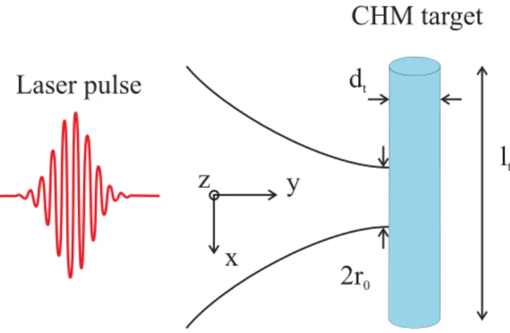
In order to investigate the proton acceleration mecha- nism in CHM, we numerically model the interaction of an ultrashort-ultraintense laser field with near-solid-density plasma with the aid of multidimensional PIC simulations using the PIConGPU code.29 Figure1(a) shows the scheme of the simulation model, which is similar to that used in the experiment of Gauthieret al.24An intense laser pulse, propa- gating along they-axis, is focused onto the CHM target with normal incidence. The laser is linearly polarized along the x-direction. A laser pulse of 800 nm wavelength is consid- ered which is Gaussian in space and time. The focused beam diameter at the target is 2r0¼5.0lm, the laser pulse duration
is 20 fs, the peak laser intensity is about 1022W/cm2, and correspondingly, the normalised laser field is aL¼68. The proposed CHM plasma target is of cylindrical shape with a diameter of dt¼2.5lm. It was assumed to be non- magnetised preionized with an initial density of the fully ion- ised plasma to be 6.961022cm3(’40nc), wherencis the critical density for 800 nm light. The computational domain is 101010lm3with a cell size of 10 nm (in longitudinal and transverse directions), and the time step is 16.7 As. Two particles per cell are considered for each species (electrons and protons). Periodic boundary conditions were used in the simulations in the transverse directions (alongx- andz-axes).
The open/absorbing boundary conditions were used along the laser propagation direction (y-axis) to reduce the compu- tational time. The peak density in simulation increases up to 2–3 times the initial plasma density so the grid size and time step are chosen carefully to resolve the electron dynamics within the relativistic collisionless skin depth (’c1=2c/xpe), wherexpeis the electron plasma frequency.
When an intense laser field (aL1) interacts with the preionised plasma, the electrons acquire an exponential energy distribution with a mean energy of kBTe
¼mec2ð ffiffiffiffiffiffiffiffiffiffiffiffiffiffiffiffiffi ð1þa2LÞ
p 1Þdue to ponderomotive acceleration.10 Here,kBis the Boltzmann constant andTeis the bulk electron temperature. With intensities ofI¼10181021W=cm2avail- able today, the ions hardly move in the electric field of the laser. As soon as the laser starts to tear off the electrons, its e(vB) force pushes electrons forward and the longitudinal electric field evolves due to the charge separation. This station- ary (quasi-static) electric field can be as high as the electric field of the laser itself. The laser ponderomotive forcefLresponsible for the laser-matter interaction can be expressed as14
fLðrÞ ¼ e2
Að4mex2LÞrELðrÞ2½1Bðcos 2xLtÞ: (1) For a linearly polarised pulse,A¼B¼1, whereas in the case of circular polarization, A¼2, B¼0, and t is the time.
According to Eq.(1), the laser ponderomotive forcefLcou- ples the incident photon flux into two primary kinetic modes:
(i) hole boring of ions accelerated by the space-charge force associated with electrons under excursion caused by the time-averaged field energy gradientsfL/ rE2Land (ii) rela- tivistic hot electrons excited by the oscillatory component of fLat a frequency of 2xL.
Formation of collisionless shocks may happen when the piston velocity exceeds the ion sound speed cS
¼ ffiffiffiffiffiffiffiffiffiffiffiffiffiffiffiffiffiffiffi ZkBTe=mi
p , wheremiis the ion mass and Z is the charge state. The shock velocity can be estimated by comparing the momentum flux of the incoming mass flow with the laser- light pressure. The normalised shock velocity can be written as14
vshock=c¼ aL
ffiffiffi2 p nc
ni
1=2 me
mi 1=2
; (2)
whereniis the ion density. The condition for shock forma- tion in terms of the laser-plasma parameter can be expressed as aL>2aðne=ncÞ,14 where a¼0.3–0.5 is the typical
FIG. 1. Scheme of the setup for the interaction of a laser pulse with a preion- ised CHM target of cylindrical shape.
033111-2 Sharmaet al. Phys. Plasmas25, 033111 (2018)
fraction of laser energy converted to ponderomotive heating of electrons. For our case ofaL¼68 andne¼40nc, this con- dition is clearly met. On the other hand, according to Eq.(1), the intense laser field pushes the front of the target and gen- erates hot electrons which prevent the Mach number M¼vshock/csfrom exceeding the critical value of about 6.5 above which RPA dominates without the formation of a shock. For the laser-plasma parameters considered in this study, M ’ 2 which excludes the possibility of the RPA dominated interaction.
III. RESULTS
A. Long driver pulses
In order to verify the validity and predictive power of our model, first we performed a simulation study with long driver pulses with similar laser-plasma parameters to those of the experiment of Gauthieret al.24The aim of this experi- ment was the realisation of a proton source with potential for enhanced emittance, flux, and energy. The linearly polarised laser pulse contained 30–50 J energy, the wavelength was 527 nm, and the pulse duration was 700 fs (intensity FWHM). After wavefront optimization with a deformable mirror, the pulses were focused by anf/3 off-axis parabola to a spot of 10 to 13lm FWHM. The estimated peak intensity on the target was 3 to 51019W=cm2. The CHM target was produced by a liquid hydrogen jet, cooled down to a temper- ature of 17 K, which then frozen with minimal mass loss by evaporation. The result was a continuous 10lm diameter cylinder of solid density (0.08 g/cm3) hydrogen.
To investigate the ion acceleration mechanism in the cryogenic hydrogen target in view of the experiment of Gauthieret al.,24 2D PIC simulations were performed with the PIConGPU code29 by using laser and target parameters from the experiment (see above). We show the schematic of the simulation set-up in Figure 1(a)which is similar to that of the experiment.24 In the simulation model, 5000 cells along the y-axis and 2048 cells transversely along the x-axis constituted the simulation box.
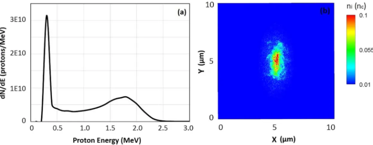
Figure 2(a) shows the calculated energy distribution of accelerated protons at 2.9 ps after the incidence of laser on
the front side of the target. We observe a peak at’1.8 MeV in the proton energy spectrum. The density of the peaked proton beam is 0.1nc which is obtained for protons in the 1.5–2.0 MeV energy range. We considered protons in the energy spectrum [shown in Fig.2(a)], which propagate close to the laser axis (diverging at an angle of10). Here, the particle numberdN/dEis about 1010/MeV, which is close to the proton numbers obtained in the experiment, by the enhanced TNSA scheme for monoenergetic ion beam pro- duction.24 The broadening of the energy spectrum can be seen due to the TNSA mechanism at the rear side of the tar- get. A spatial density profile of the proton beam is shown in Fig. 2(b). These simulation results, especially the presence of a quasi-monoenergetic peak in the spectrum, support the reasonably good predictive power of our model.
B. Few cycle driver pulses
To investigate the mechanism of proton acceleration and the involved laser-plasma dynamics with a few-cycle ultraintense laser pulse, we carried out 3D PIC simulations of the interaction of a 20-fs, 2-PW laser pulse with a CHM target. The assumed laser parameters correspond to the PW laser facility at ELI-ALPS which is currently in the develop- ment phase.25 The scheme of the laser interaction with the CHM target is shown in Fig.1, as before.
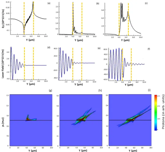
A summary of simulation results is shown in Fig. 3 where the evolution of the longitudinal electric field [(a)–(c)], the electric field of the laser [(d)–(f)], and the ion phase space distribution [(g)–(i)] is illustrated at different time instants of t¼50 fs, 87 fs, and 100 fs. Time instant t¼0 corresponds to the arrival (1/e2of peak intensity) of the laser pulse at the front surface of CHM. Initially, the laser pulse drives the front surface due to radiation pressure. The critical density surface pushed forward at the hole boring velocity, causing the buildup of an ion density spike (see below). Initially, electrons (followed by protons) are pressed inwards by the radial ponderomotive force of the laser along the laser propagation direction. Thus, the plasma compres- sion due to the radiation pressure provides the required con- ditions for the shock wave field. As the laser is stopped around the critical density and steepens the plasma profile,
FIG. 2. Simulation results for a long driver pulse interacting with a CHM plasma target. (a) The proton energy distribution for 700 fs driver pulses at 2.9 ps;
(b) the spatial distribution of proton energy density with10of angular divergence. The ion density is normalised with the critical density.
the heated electrons propagate through the back side of the target, where they find unperturbed plasma at a similar den- sity, driving a return current that pulls the background elec- trons to the laser region where they are accelerated.
Therefore, thin targets with peak density around the critical density allow for an efficient heating of the entire plasma.
The initial build-up of the return current together with the quick recirculation of the heated electrons due to the space charge fields at the front and at the back of the target will lead to a uniform temperature profile, which is crucial in order to have a uniform shock velocity and a uniform ion reflection. The temperature of the electron is consistent with the ponderomotive scaling for the hot electrons, kBThot
¼25:0MeV. Here, in the case of the intense laser interaction with the target when ne=cncw 0:5, the strong shock wave field accelerates the ions originating from the front side of the target.
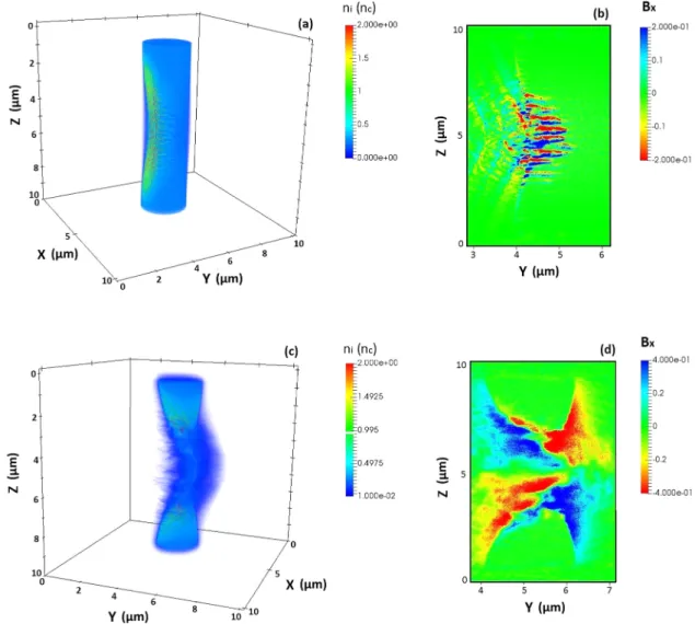
Figure 4illustrates the evolution of ion density (a) and (c) and magnetic field distribution (b) and (d) at time instant before (a) and (b) and after (c) and (d) shock formation. A strong compression in plasma density is observed between the laser-plasma interface and the shock front and strong
filamentation in the upstream region [Figs. 4(a) and 4(b)].
We observe a sharp density modulation of protons near to the front surface of the target. Such a strong density modula- tion is due to the self-generated electromagnetic field in the plasma. The magnetic field (Bx) distribution in the YZ plane also shows the filamentary structure [Fig.4(b)], which seems to be generated at the front surface of the target.
Filamentation in plasma density and magnetic field can be understood on the basis of counterstreaming currents as men- tioned before. In order to observe the propagation of laser accelerated relativistic electrons within the target, local charge neutrality must be maintained. It can be achieved when a much larger return current involving a much larger number of slowly moving electrons is driven by beam to neutralise the fast current density such thatjfþjr¼0, where jfis the fast electron current density andjris the return cur- rent density. The two counterstreaming currents are suscepti- ble for the Weibel unstability.30 Since the laser generated electrons are too hot to filament in the background plasma, it is the cold return current which filaments.
Figure4(c) shows the shock field driven proton density distribution driven by the shock field at t¼87 fs, when the
FIG. 3. Simulation results for the few cycle-driver pulse interacting with the CHM plasma target. Evolution of longitudinal electric field (a)–(c), laser field (d)–(f), and ion phase space distribution (g)–(i) for the cylindrical target (lengthlt¼9lm and diameterdt¼2.5lm) driven by 20 fs pulses at time instant t¼50 fs (a), (d), and (g), 87 fs (b), (e), and (h), and 100 fs (c), (f), and (i). The colour bar shows the ion number density.
033111-4 Sharmaet al. Phys. Plasmas25, 033111 (2018)
shock has been formed and propagates in background plasma.
A very strong quasistatic magnetic field of 0.1 G is observed [Fig.4(d)]. The simulation results agree well with the theoreti- cal estimation of B¼ ð1=2pÞ ffiffiffiffiffiffiffiffiffiffiffiffiffiffiffiffiffiffiffi
ðcrnc=nrÞ
p ðmecxL=eÞ for the magnetic field [26]. Here,nr is the density of return current electrons andcris the relativistic Lorentz factor of return cur- rent electrons, which can be obtained by calculating the Larmor radius of the electrons to the filament wavelength.31
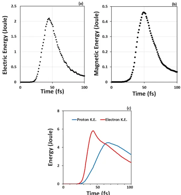
In order to understand the evolution of self-generated electric and magnetic fields, we numerically observe the energy associated with these fields as well as the energy absorbed by the plasma particles. Figure5shows the tempo- ral evolution of the energy associated with the quasistatic longitudinal electric fieldEy[Fig.5(a)], the quasistatic mag- netic fieldBx[Fig.5(b)], and the plasma particles (electrons and protons) [Fig.5(c)]. As it can be seen from Fig.5(a), the energy associated with the electric field is the largest around 50 fs. This electric field is associated with the shock wave and reflects a large fraction of the ion population. As the reflected protons propagate further in the plasma while being counterstreamed with the background plasma, a strong magnetic field builds up, as shown in Fig. 5(b). This
self-generated quasi-static magnetic field is an important finding in this study, because it deflects the proton beam towards the laser propagation axis and spatially modifies the proton beam distribution. Figure 5(c) depicts the temporal evolution of kinetic energy of electrons and protons.
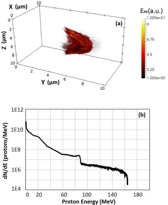
Figure 6(a) shows the spatial distribution of the proton energy density of the proton beam at time of peak acceleration (t¼100 fs). The spatial profile of the proton beam is close to a Gaussian distribution. The beam is collimated due to the magnetic field (Bx) along the laser propagation direction.
Figure6(b)shows the energy spectrum of protons which prop- agate close to they-axis within a half divergence angle of 10. The maximum (cut-off) energy obtained in this case is about 160 MeV. We also observed a peak at 80 MeV in proton energy distribution which is a characteristic of collisionless shock wave acceleration of protons. The maximum proton energy mainly depends on ions reflected from the shock field, and it can be estimated using Eq.(2) for the shock velocity as16 EProtonðMeVÞ ’74Ið1021W=cm2Þ=neð1022cm3Þ. The maximum proton energy obtained from this formula is about 125 MeV, which is less than the simulation results of 160 MeV. The enhancement in maximum proton energy
FIG. 4. Evolution of the ion density (a) and (c) and magnetic field distribution (b) and (d) for a few-cycle driver pulse interacting with a CHM plasma target.
(a) and (b) refer to the when the peak laser field interacts with the front surface of the target (t¼50 fs), and (c) and (d) refer tot¼87 fs. The colour bars show the variation in ion density (a) and (c) and magnetic field distribution (b) and (d). The ion density (ni) is expressed in units of critical plasma density (nc), and the magnetic field (Bx) is in units of Gauss.
observed in the simulation can be seen as an additional accel- eration at the rear surface of the target due to quasi-static elec- tric and magnetic field [as shown in Figs.3(c)and4(d)]. It is interesting to note that the analytical formula given above pre- dicts a maximum proton energy up to 250 MeV for a focused laser intensity of 21022W=cm2 on the target, which is very promising for medical applications.
The spatial distribution of proton energy density shows that high-energy protons are collimated along the laser prop- agation direction within a small area. Besides peak proton energy, another important point in terms of applications is the conversion efficiency of laser energy to the proton beam.
This can be estimated from the ratio of the total proton energy to the laser energy. For the target size ofdt¼2.5lm, we observed a conversion efficiency of ’1% for 1010 pro- tons with energy higher than 10 MeV, accelerated along the laser propagation direction.
Figure 7 shows the temporal evolution of laser pulse energy (dashed lines) and the kinetic energy of accelerated
protons (solid lines). The 3D simulations performed for differ- ent target diameters of 1lm, 2.5lm, and 5lm (with the same laser-plasma parameters as before) clearly show a sensitive dependence of the total proton energy on the target size (Fig.
7). Therefore, the optimal choice of the laser beam size and target diameter is critical for transporting maximum energy from the laser field to the protons. We found that a laser beam size slightly larger than the target diameter resulted in a higher proton energy. For our 5-lm diameter laser beam, the highest efficiency was achieved with the 2.5-lm diameter target.
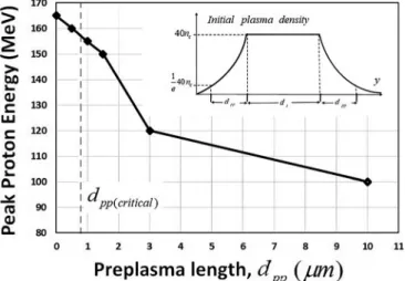
It shall be noted that the presence of a preplasma can influence the laser-plasma interaction dynamics. 2D3V PIC simulations were performed to estimate the preplasma effects on proton acceleration. We numerically varied the preplasma scale length between 0 and 10lm to investigate its relevance for proton energy distributions. The results show that for a preplasma of about the critical scale length 0:13kLa0:50 ¼0:88lm or shorter, there is only a small and smooth variation of the proton density at the rear surface.
FIG. 5. Temporal evolution of the energy of the quasistatic electric field (Ey) (a), magnetic field (Bx) (b), and of the kinetic energy associated with the electrons and protons.
033111-6 Sharmaet al. Phys. Plasmas25, 033111 (2018)
These findings are in agreement with the recent experimental and simulation studies.26 The dependence of the maximum (cut-off) proton energy on the preplasma length is shown in Fig. 8. We find that a preplasma up to about the critical length does not show a significant effect on the peak proton energy. However, a preplasma over the critical length can significantly reduce the proton energy.
Recent experimental results28with the CHM target have achieved a maximum proton energy of 20 MeV with 2.6 J of laser energy, where it has also been observed that the proton energy was limited by the preplasma effect. This is in good agreement with our simulation results (as shown by Fig.8).
Thus, based on the most recent experiment results27,28 and the results illustrated in this study, we can expect that future experiments with higher pulse energies and precisely con- trolled prepulses can deliver higher proton energies.
IV. CONCLUSION
Laser-driven proton acceleration from mass-limited cryogenic hydrogen microjet targets was numerically
investigated for long (700 fs) and few-cycle (20 fs) laser pulses. For long pulses, we numerically observed a quasi- monoenergetic proton peak at 1.8 MeV, in reasonable accor- dance with the experimental finding of Gauthier et al.24 In order to achieve higher proton energy, a new regime of pro- ton acceleration was numerically investigated by using 20-fs pulses with a 2-PW peak power and 1022W/cm2 focused intensity with controlled prepulses. Such a high-power few- cycle laser will be available in the near future, for example, at ELI-ALPS.25 Proton energies as high as 160 MeV were predicted by simulations with a quasi-monoenergetic peak around 80 MeV. This peak is characteristic for collisionless shock-wave acceleration. It is observed that the proton energy can be maximised when the laser beam size becomes slightly larger than the target diameter. A very strong quasi- static magnetic field of a few Gauss was observed, which modulates the spatial density profile of the proton beam along the laser propagation direction. Such strong quasi- static magnetic fields may allow us to study the astrophysical process at advanced laser facilities. A preplasma of length over the critical value26 can reduce the proton energy, but
FIG. 6. Spatial distribution of proton energy density and proton energy dis- tribution. (a) Spatial distribution of proton energy density for target diame- terdt¼2.5lm; (b) energy spectrum at t¼100 fs of protons accelerated along the laser propagation direction within a divergence angle of 10.
the use of a double plasma mirror can mitigate such effects.
Even higher maximum proton energies up to 250 MeV and beyond can be expected on the basis of simulation results in this work and analytical estimations16 by focusing the laser to still higher intensities of 21022W/cm2 on the target.
Such high proton energies are required for cancer therapy to treat deep-seated tumors.1
ACKNOWLEDGMENTS
We performed PIC simulations utilizing the open-source code PIConGPU version 0.1.229 in this research. We acknowledge support of the Department of Information Services and Computing, Helmholtz-Zentrum Dresden- Rossendorf (HZDR), Germany, for providing access to the GPU Compute Cluster Hypnos. This work was funded as part of the European Cluster of Advanced Laser Light Sources (EUCALL) project which has received funding from the European Union’s Horizon 2020 research and innovation programme under Grant Agreement No. 654220. This work was supported in part by the Hungarian Scientific Research Fund (OTKA) under Grant No. 113083. J. A. F€ul€op
acknowledges support from a Janos Bolyai Research Scholarship (Hungarian Academy of Sciences). The present scientific contribution is dedicated to the 650th anniversary of the foundation of the University of Pecs, Hungary.
1V. Malka, J. Faure, Y. A. Gauduel, E. Lefebvre, A. Rousse, and K. Ta.
Phuoc,Nat. Phys.4, 447 (2008).
2E. L. Clark, K. Krushelnick, J. R. Davies, M. Zepf, M. Tatarakis, F. N.
Beg, A. Machacek, P. A. Norreys, M. I. K. Santala, I. Watts, and A. E.
Dangor,Phys. Rev. Lett.84, 670 (2000).
3A. Maksimchuk, S. Gu, K. Flippo, D. Umstadter, and V. Yu. Bychenkov, Phys. Rev. Lett.84, 4108 (2000).
4R. A. Snavely, M. H. Key, S. P. Hatchett, T. E. Cowan, M. Roth, T. W.
Phillips, M. A. Stoyer, E. A. Henry, T. C. Sangster, M. S. Singh, S. C.
Wilks, A. MacKinnon, A. Offenberger, D. M. Pennington, K. Yasuike, A.
B. Langdon, B. F. Lasinski, J. Johnson, M. D. Perry, and E. M. Campbell, Phys. Rev. Lett.85, 2945 (2000).
5S. C. Wilks, A. B. Langdon, T. E. Cowan, M. Roth, M. Singh, S. Hatchett, M. H. Key, D. Pennington, A. MacKinnon, and R. A. Snavely, Phys.
Plasmas8, 542 (2001).
6P. Mora,Phys. Rev. Lett.90, 185002 (2003).
7J. Fuchs, P. Antici, E. d’Humieres, E. Lefebvre, M. Borghesi, E.
Brambrink, C. A. Cecchetti, M. Kaluza, V. Malka, M. Manclossi, S.
Meyroneinc, P. Mora, J. Schreiber, T. Toncian, H. Pepin, and P. Audebert, Nat. Phys.2, 48 (2006).
8L. Robson, P. T. Simpson, R. J. Clarke, K. W. D. Ledingham, F. Lindau, O. Lundh, T. McCanny, P. Mora, D. Neely, C.-G. Wahlstr€om, M. Zepf, and P. McKenna,Nat. Phys.3, 58 (2007).
9T. E. Cowan, J. Fuchs, H. Ruhl, A. Kemp, P. Audebert, M. Roth, R.
Stephens, I. Barton, A. Blazevic, E. Brambrink, J. Cobble, J. Fernandez, J.-C. Gauthier, M. Geissel, M. Hegelich, J. Kaae, S. Karsch, G. P. L. Sage, S. Letzring, M. Manclossi, S. Meyroneinc, A. Newkirk, H. Pepin, and N.
Renard-LeGalloudec,Phys. Rev. Lett.92, 204801 (2004).
10S. C. Wilks, W. L. Kruer, M. Tabak, and A. B. Langdon,Phys. Rev. Lett.
69, 1383 (1992).
11A. P. L. Robinson, P. Gibbon, M. Zepf, S. Kar, R. G. Evans, and C. Bellei, Plasma Phys. Controlled Fusion51, 024004 (2009).
12C. A. J. Palmer, N. P. Dover, I. Pogorelsky, M. Babzien, G. I. Dudnikova, M. Ispiriyan, M. N. Polyanskiy, J. Schreiber, P. Shkolnikov, V.
Yakimenko, and Z. Najmudin,Phys. Rev. Lett.106, 014801 (2011).
13T. Esirkepov, M. Borghesi, S. V. Bulanov, G. Mourou, and T. Tajima, Phys. Rev. Lett.92, 175003 (2004).
14A. Macchi, F. Cattani, T. V. Liseykina, and F. Cornolti,Phys. Rev. Lett.
94, 165003 (2005).
15L. O. Silva, M. Marti, J. R. Davies, R. A. Fonseca, C. Ren, F. S. Tsung, and W. B. Mori,Phys. Rev. Lett.92, 015002 (2004).
16D. Haberberger, S. Tochitsky, F. Fiuza, C. Gong, R. A. Fonseca, L. O.
Silva, W. B. Mori, and C. Joshi,Nat. Phys.8, 95 (2012).
17F. Fiuza, R. A. Fonseca, J. Tonge, W. B. Mori, and L. O. Silva,Phys. Rev.
Lett.108, 235004 (2012).
18F. Fiuza, A. Stockem, E. Boella, R. A. Fonseca, L. O. Silva, D.
Haberberger, S. Tochitsky, W. B. Mori, and C. Joshi,Phys. Plasmas20, 056304 (2013).
19A. Henig, D. Kiefer, K. Markey, D. C. Gautier, K. A. Flippo, S. Letzring, R. P. Johnson, T. Shimada, L. Yin, B. J. Albright, K. J. Bowers, J. C.
Fernandez, S. G. Rykovanov, H.-C. Wu, M. Zepf, D. Jung, V. K.
Liechtenstein, J. Schreiber, D. Habs, and B. M. Hegelich,Phys. Rev. Lett.
103, 045002 (2009).
20D. Jung, L. Yin, B. J. Albright, D. C. Gautier, S. Letzring, B. Dromey, M.
Yeung, R. H€orlein, R. Shah, S. Palaniyappan, K. Allinger, J. Schreiber, K.
J. Bowers, H. C. Wu, J. C. Fernandez, D. Habs, and B. M. Hegelich,New J. Phys.15, 023007 (2013).
21L. Yin, B. J. Albright, K. J. Bowers, D. Jung, J. C. Fernandez, and B. M.
Hegelich,Phys. Rev. Lett.107, 045003 (2011).
22M. Roth, D. Jung, K. Falk, N. Guler, O. Deppert, M. Devlin, A. Favalli, J.
Fernandez, D. Gautier, M. Geissel, R. Haight, C. E. Hamilton, B. M.
Hegelich, R. P. Johnson, F. Merrill, G. Schaumann, K. Schoenberg, M.
Schollmeier, T. Shimada, T. Taddeucci, J. L. Tybo, F. Wagner, S. A.
Wender, C. H. Wilde, and G. A. Wurden,Phys. Rev. Lett.110, 044802 (2013).
23A. P. L. Robinson, M. Zepf, S. Kar, R. G. Evans, and C. Bellei,New J.
Phys.10, 013021 (2008).
FIG. 7. Temporal evolution of laser pulse energy (dashed lines) and kinetic energy of protons (solid lines) for different target diameters ofdt¼1lm (red), 2.5lm (green), and 5.0lm (blue). The laser beam parameters were the same as in the previous simulations.
FIG. 8. Dependence of peak proton energy on the preplasma scale length.
Laser-plasma parameters are the same as in previous simulation results.
033111-8 Sharmaet al. Phys. Plasmas25, 033111 (2018)
24M. Gauthier, J. B. Kim, C. B. Curry, B. Aurand, E. J. Gamboa, S. G€ode, C. Goyon, A. Hazi, S. Kerr, A. Pak, A. Propp, B. Ramakrishna, J. Ruby, O. Willi, G. J. Williams, C. R€odel, and S. H. Glenzer,Rev. Sc. Instr.87, 11D827 (2016).
25Seehttp://www.eli-alps.hufor ELI-ALPS.
26S. Gode, C. R€odel, K. Zeil, R. Mishra, M. Gauthier, F.-E. Brack, T. Kluge, M. J. MacDonald, J. Metzkes, L. Obst, M. Rehwald, C. Ruyer, H.-P.
Schlenvoigt, W. Schumaker, P. Sommer, T. E. Cowan, U. Schramm, S.
Glenzer, and F. Fiuza,Phys. Rev. Lett.118, 194801 (2017).
27M. Gauthier, C. B. Curry, S. Gode, F. E. Brack, J. B. Kim, M. J.
MacDonald, J. Metzkes, L. Obst, M. Rehwald, C. Rodel, H. P.
Schlenvoigt, W. Schumaker, U. Schramm, K. Zeil, and S. H. Glenzer, Appl. Phys. Lett.111, 114102 (2017).
28L. Obst, S. Gode, M. Rehwald, F. E. Brack, J. Branco, S. Bock, M.
Bussmann, T. E. Cowan, C. B. Curry, F. Fiuza, M. Gauthier, R. Gebhardt, U. Helbig, A. Huebl, U. Hubner, A. Irman, L. Kazak, J. B. Kim, T. Kluge, S. Kraft, M. Loeser, J. Metzkes, R. Mishra, C. Rodel, H. P. Schlenvoigt, M. Siebold, J. Tiggesbaumker, S. Wolter, T. Ziegler, U. Schramm, S. H.
Glenzer, and K. Zeil,Sci. Rep.7, 10248 (2017).
29M. Bussmann, H. Burau, T. E. Cowan, A. Debus, A. Huebl, G. Juckeland, T.
Kluge, W. E. Nagel, R. Pausch, F. Schmitt, U. Schramm, J. Schuchart, and R.
Widera, inProceedings of International Conference on High Performance Computing, Networking, and Storage Analysis(2013), Vol. 5, p. 1.
30E. S. Weibel,Phys. Rev. Lett.2, 83 (1959).
31R. C. Davidson, D. A. Hammer, I. Haber, and C. E. Wagner,Phys. Fluids 15, 317 (1972).
View publication stats View publication stats