Nuclear Inst. and Methods in Physics Research, A 987 (2021) 164841
Contents lists available atScienceDirect
Nuclear Inst. and Methods in Physics Research, A
journal homepage:www.elsevier.com/locate/nima
Technical Notes
1 kHz laser accelerated electron beam feasible for radiotherapy uses:
A PIC–Monte Carlo based study
R. Polanek
a,∗, Nasr A.M. Hafz
a,b,c, Zs. Lécz
a, D. Papp
a, C. Kamperidis
a, Sz. Brunner
a, E.R. Szabó
a, T. Tőkés
a, K. Hideghéty
a,daELI-ALPS, ELI-HU Non-Profit Ltd. Wolfgang Sandner u. 3, H-6728 Szeged, Hungary
bNational Laboratory on High Power Laser and Physics, SIOM, CAS, Shanghai 201800, China
cDepartment of Plasma and Nuclear Fusion, Nuclear Research Center, Atomic Energy Authority, Abu-Zabal 13759, Egypt
dUniversity of Szeged, Faculty of Medicine, Department of Oncotherapy, Korányi fasor 12., H-6720, Szeged, Hungary
A R T I C L E I N F O
Keywords:
LWFA acceleration Electron radiotherapy
A B S T R A C T
Laser wakefield acceleration (LWFA) offers a promising compact solution for the production of high and very high energy electron (VHEE) beams, which have an ultrashort pulse duration with a high instantaneous dose rate and small source size. These unique properties are of radiobiological as well as clinical interest. In this paper we focus on the potential application of high repetition rate LWFA electron beams for radiobiology and radiotherapy. On the basis of particle-in-cell (PIC) and Monte Carlo simulations we propose that, using a commercially available 1 kHz laser system one can generate electron beams with 35.7 MeV mean energy and 3 pC electron bunch charge at 1 kHz repetition rate to deliver a dose rate of 18 Gy/min, which could be extremely useful for real radiotherapy applications. Thanks to the high repetition rate, dose delivery can be performed with high precision making this system a potential alternative to conventional clinical electron accelerators.
1. Introduction
It is now sixty-seven years since the first dedicated medical electron linear accelerator (LINAC) was used to treat cancers. This milestone opened new prospects in the development of radiothreapy techniques, which have remained indispensable in the fight against cancer. The main paradigm of radiotherapy has not changed essentially over the years. However, the underlying technology and the techniques have significantly improved. Intensity modulated radiation therapy (IMRT), image-guided radiotherapy (IGRT), stereotactic body radiation ther- apy (SBRT), stereotactic ablative radiotherapy (SABR) are just a few radiotherapy techniques which have significantly benefited from the technological enhancement of particle accelerators.
Electron beam therapy is a widely used radiotherapy technique for the irradiation of superficial target volumes. Accelerators currently used in clinical practices generate electron beams with energies be- tween 6 and 24 MeV, which allows a relatively uniform dose delivery to a depth of 1 to 6 cm. These clinical electron beams are used in the treatment of skin, breast and chest wall cancers; peripheral lym- phatic regions of head and neck cancers; and for the irradiation of other neoplastic diseases. Electron beams can also be used in intra- operative applications for selective dose delivery to the tumor bed after
∗ Corresponding author.
E-mail address: robert.polanek@eli-alps.hu(R. Polanek).
the surgical removal of pancreatic, colorectal cancers and soft tissue sarcomas [1].
As far as the particle accelerator technology is concerned, there is a trend in using high-power laser beams and gaseous plasma (fully ion- ized gas) media to build compact electron accelerators. In 1979, Tajima and Dawson [2] proposed a scheme for electron acceleration to rel- ativistic energies by ultraintense electrostatic plasma waves (called
‘‘laser wakefield’’) driven by ultrashort focused laser pulses during their propagation in under-dense gaseous plasma medium. This laser–plasma acceleration scheme is called ‘‘laser wakefield acceleration’’ (LWFA) and it has attracted significant interest in recent years [3–5] due to the availability of commercial, ultracompact, solid-state terawatt laser systems [6].
Generally, the use of optical mirrors instead of high-power magnets provides relative flexibility in beam delivery, and offers new possi- bilities in facility design, cost reduction, and in the development of new radiotherapy techniques. These advantages are not self-evident in experimental laser facilities which require sophisticated and delicate infrastructure. However, the inherent strengths of such systems, and the rapid technological progress make laser–plasma acceleration in general and LWFA in particular a promising alternative to conventional RF-based accelerators.
https://doi.org/10.1016/j.nima.2020.164841
Received 1 June 2020; Received in revised form 30 October 2020; Accepted 3 November 2020 Available online 5 November 2020
0168-9002/©2020 The Authors. Published by Elsevier B.V. This is an open access article under the CC BY license (http://creativecommons.org/licenses/by/4.0/).
With LWFA techniques it is easy to produce very high energy elec- tron beams (VHEE, electrons with energies above 50 MeV). VHEE beam therapy has recently emerged as a novel option for cancer radiotherapy.
In silico studies have shown that VHEE beams have a more favor- able dose distribution than advanced photon techniques and in some situations, the results approach the charged particle therapy values.
Monte Carlo simulation based plans, using electron beams with energies above 100 MeV provided a very good dose conformation, while offering significantly improved dose sparing of healthy tissue when compared to intensity modulated and volumetric arc photon therapy [7–10]. VHEE plans were superior to IMRT plans but they could also be delivered orders of magnitude faster than photon plans mainly due the higher particle production efficiency and the ability to steer charged particles in a millisecond timescale [10].
However, such VHEE beams are only available at a few academic laboratories. For example, the Next Linear Collider Test Accelerator (NLCTA) located at the SLAC National Accelerator Laboratory is capa- ble of producing high-brightness electron beams, with energy between 60 and 150 MeV which supports the development of the VHEE ther- apy [11]. There are only few more such experimental facilities where VHEE beams can be produced for experimental studies. In order to make VHEE beams widely available, LWFA offers a potential alternative to conventional RF-based accelerators for the production of electron beams.
Furthermore, LWFA electron beams have several unique properties which make them attractive for applications in radiobiology and ra- diotherapy. For example, the low divergence of the generated electron beams facilitates the formation of microbeams, which in the MeV energy range may be beneficial in cancer therapy [12,13]. In general, an electron beam having a short bunch duration (ps at the sample position) leads to a very high instantaneous radiation dose rate. This can be useful for the state-of-the-art FLASH technique, which requires a high instantaneous dose rate. This novel radiotherapy technique seems to increase the therapeutic ratio by reducing both the acute side effects on normal tissues and late complications [14,15]. However, recent experiments show that several factors such as instantaneous and mean dose rate, total dose and the pulsatile nature of the beam may influence the FLASH effect. So far, no clear consensus has been reached in this issue. A valuable review on this subject has been recently published by Wilson et al. [16].
In fact, LWFA electron bunches are extremely short; they are in the order of a few femtoseconds (fs) immediately after acceleration [17], which enables radiation chemists to conduct pulse radiolysis experi- ments at a time scale which has not been available until now [18].
Such ultrafast pulse radiolysis (also known as femtolysis) experiments significantly contribute to our understanding of the biological effects of radiation.
However, active research in LWFA has revealed some efficiency, stability and reliability issues that need to be resolved prior to its implementation. Efficiency in terms of pulse charge and repetition rate ensures the necessary dose rate, which must be at least 4 Gy/min for real radiotherapy applications. The moderate stability of LWFA accelerators in terms of energy and pulse charge is the primary task which requires immediate attention before such accelerators are intro- duced into real radiobiological or medical applications. Furthermore, the reliability and effectiveness of beam shaping must be enhanced.
Fortunately, there is a significant progress toward stable LWFA electron beams [19,20].
In this study we investigate high repetition rate LWFA electron beams recently reported by Guénot et al. [21] and Ouillé et al. [22]. We analyze the potential of those beams for radiobiology and radiotherapy purposes. High repetition rate electron beams can be generated by com- mercially available 1 kHz laser systems (multi-TW power & few-cycle pulse duration); one such system is currently operational at ELI-ALPS Research Institute [6]. Using Monte Carlo simulations we demonstrate that this type of 1 kHz LWFA is capable of generating a sufficient dose
Fig. 1. The semi-realistic model of irradiation geometry used in the MC simulations.
The laser beam (b) enters the vacuum chamber (a) and is focused using optics (c) onto a gas jet target (d) where LWFA acceleration takes place. The accelerated electrons (f) exit the vacuum chamber through a Mylar window (e). Absorbed dose is calculated in the water phantom (g) placed at different source-to-surface distances (SSD).
rate for practical radiobiological or medical applications. The critical issues such as low radiation dose per electron bunch and the relatively low stability of such systems can, in principle, be compensated for if the LWFA operates at 1 kHz. Additionally, we outline some practical issues and pitfalls which need to be addressed before such systems are used in real applications.
2. Methods
To assess the dosimetric characteristics, Monte Carlo simulations were performed based on the Geant4 (version 10.3) Monte Carlo simu- lation framework [23,24] on a workstation with an Intel Xeon 16-core processor.
Fig. 1 shows the semi-realistic geometry used in the simulation scenarios. Electron acceleration takes place in the vacuum chamber (a) at the gas-jet target (d). The accelerated electron beam exits the vacuum chamber through a300 μmthick circular Mylar window (e).
The absorbed dose is calculated in a water phantom (g), a box with 6 mm thick Plexiglas walls filled with liquid water and placed in front of the Mylar window at different source to surface distances (SSD). The materials for all geometric components of the simulation were set using the materials defined in the NIST materials database [25].
The electron beam source was simulated based on the electron beam characteristics obtained from 3D particle-in-cell (PIC) simula- tions, which were performed using the EPOCH open source code [26]
with the parameters of the SYLOS II laser system available at ELI-ALPS.
The position, energy and direction of each electron in the beam were derived from a data file generated by the 3D PIC simulation, taking in account the correct weighting factor, as well as the position and momentum of each pseudo-electron. These parameters were then used to set up the initial electron parameters in the MC simulations.
The PIC simulations used the following laser parameters: pulse duration 8 fs (FWHM), peak power 4 TW (corresponding to 30 mJ total energy per pulse) and 1 kHz repetition rate. The laser beam was focused to a2.2 μmfocal spot diameter (FWHM), resulting in2⋅1019 W∕cm2 peak intensity. The Rayleigh length of such a tightly focused laser pulse is around100 μm, wherefore we use a very narrow He (helium) gas jet as a target, where the maximum electron density after ionization is 𝑛0 = 4⋅1019cm−3. The spatial density profile is described by a super Gaussian function:
𝑛𝑒=𝑛0𝑒−
(𝑧−𝑧0 )4
2𝜎4 , (1)
where 𝑧0 = 70 μm and 𝜎 = 38 μm. In the radial direction the plasma density is assumed to be uniform. The laser pulse is focused at 𝑧 = 50 μm, 20 μmbefore the center of the gas jet. Due to tight focusing, the laser intensity increases quickly along the propagation
axis, which results in electron self-injection into the wakefield. The injected electrons are accelerated over a distance of 50 μmreaching an average energy above 30 MeV with a small energy-spread, as shown below.
The simulation grid was 35 nm in the 𝑧 direction and 50 nm in the lateral directions, which means that each macroparticle (pseudo- electron) contains 875 real electrons. The plasma electrons are rep- resented by 4 particles per cell. For the field solver we use a special method presented by Lehe et al. [27], in order to compensate for the grid dispersion, which can generate errors in the laser propagation.
The depth dose was scored for different SSD distances by a 3D ROOT histogram. The number of bins in all directions were chosen to form a 1 mm3 voxel size. The 100 cm reference SSD distance was chosen in our discussion, which is the standard SSD distance used in clinical dosimetry measurements.
The physics of the simulations were set up using the physics-list mechanism of the Geant4 toolkit and the QGSP_BIC_HP_EMZ physics models, recommended for medical uses [28]. This physics-list includes the hadronic models from which the photo-nuclear and electro-nuclear interactions are useful for our purposes. The EMZ option contains the electromagnetic physics models, including the photoelectric effect, Compton and Rayleigh scattering for gamma particles and for charged particles ionization and Bremsstrahlung. The range cut was set to 30 μm, which is converted at initialization time into energy threshold for secondary gamma, electron, positron and proton production.
3. Results and discussion
As stated in the Introduction, our main aim is to assess the potential of using a 1 kHz laser driven electron beam for radiotherapy and radio- biology applications. Recently Guénot et al. [21] reported high-quality 6 MeV relativistic electron beams having an energy spread of 3 MeV and a charge of∼ 0.5 pCwith 30% fluctuation using 1 kHz repetition rate, single-cycle, 2.1 mJ laser pulses with 3.4 fs pulse duration in nitrogen gas jet.
However, reliable radiotherapy applications require 6 MeV or greater electron energies. Based on our PIC simulations, such beams can be produced with the parameters of the SYLOS II laser system available at ELI-ALPS. The SYLOS II laser is a 1 kHz repetition rate ‘‘few-cycle’’
laser with optical parametric chirped pulse amplification (OPCPA), which generates 5 TW, few-cycle laser pulses at a high repetition rate, with a central wavelength of 880 nm. The pulse energy is over 35 mJ with less than 8 fs pulse duration, combined with remarkable long- term stability. SYLOS II is the first laser system to have demonstrated multi-TW, few-cycle laser pulses at a high repetition rate [6].
Fig. 2ashows the energy spectra of the accelerated electrons right after the acceleration (solid line) and at the phantom surface (dashed line). The corresponding average kinetic energy of the accelerated electrons are 35.97 MeV and 35.73 MeV, respectively with an FWHM of≈ 6 MeV. The slight difference between the two spectra is the result of electron scattering during propagation from the plasma point to the phantom surface. Because the electrons are light particles, they undergo considerable scatter during propagation. During this, their energy and propagation direction slightly change and some electrons are lost from the beam resulting in an energy spectrum with less intensity and shifted toward lower energies and with broadened energy peaks. This effect is more evident at low than at high energies. Therefore, at highly relativistic energies this scattering effect is negligible, which is also confirmed by the mean kinetic energies.
The spectra presented in Fig. 2a contain electrons with kinetic energies above 20 MeV, however, there is a non-negligible, low-energy background (Fig. 2b). These low energy electrons are usually generated with a large divergence angle, therefore they do not contribute to the absorbed dose and were omitted from the simulations. On the other hand, such electrons produce considerable Bremsstrahlung radiation
Fig. 2. (a) The energy spectra of the simulated electron beam at the acceleration site (solid line) and at the phantom surface situated at an SSD of 100 cm. The long high- energy tail of the energy spectrum is a specific feature of the self-injection mechanism.
(b) The energy spectra of electrons with low energy (up to 20 MeV). They are excluded from simulations due to their large divergence.
when they are dumped, which must be considered in terms of radiation protection.
The long high-energy tail of the energy spectrum is a specific feature of the self-injection mechanism in LWFA. Here, electrons are accelerated during the initial phase of the injection, when all electrons are located at the peak electric field of the ion cavity. This process is very sensitive to the laser and plasma parameters. Consequently, the amount of electrons is so low that they are ignored in experiments.
The multi-peak nature of the energy spectra is believed to be a natural outcome of the LWFA acceleration process in high-density plasma due to the extremely high-field gradient of the plasma wave.
In other words, since the electron bunch size in 3D is around1 μm3, it means that some electrons get slightly out of the extremely-narrow acceleration phase during the propagation in the wake behind the laser pulse, which results in minor peaks around the main high-energy peak.
It is also a result of the slightly different velocity of the accelerated elec- trons in comparison to the wakefield phase velocity. This phenomenon, which is known as the ‘‘dephasing effect’’ can be mitigated by a careful control of plasma density or by some plasma density profiling [29–31].
Such a multi-peak spectrum may produce some inhomogeneity in the depth dose distribution, however this effect can be neglected as long as the energy peaks are close to one another. This means that the spectrum can be approximated with a single, broadened-energy peak. This wide energy peak produces a depth dose distribution with a broader and flatter plateau around the depth of dose maximum than a narrower energy peak, which can be useful when large volumes of interest need to be irradiated homogeneously.
As can be seen in Fig. 3, the produced electron beam is slightly asymmetric in the transverse plane (Figs. 3aand3b), and its propaga- tion direction is – to some extent – different from the z direction. Both properties are due to the linear polarization of the laser pulse. Indeed, the electric field of the laser pulse oscillates along the x direction, thus the injected electrons will have slightly larger momentum in direction that. However, this beam asymmetry can be ignored because the scattering effects in the exit window and air smooth the electron distribution and lead to a Gaussian spatial distribution (Figs. 3cand 3d). Furthermore, the resulting deviation in the direction of propa- gation with respect to the z axis is well below 10 mrad, which can be considered about the same as the maximum shot-to-shot pointing angle instability of the electron beam, a common issue with LWFA electron beams. However, even this small but random pointing angle instability is compensated for by the 1 kHz repetition rate of the system.
Consequently, in practice, we obtain a slightly enlarged, Gaussian shaped and centered electron distribution. Furthermore, this also means that the issue of shot-to-shot reproducibility in terms of the electrons’
spatial distribution and propagation direction can be neglected as long as the propagation angle is smaller than the pointing angle instability.
Fig. 3. The electrons angular distribution in function of their kinetic energy in x–z plane3aand in y–z plane3bimmediately after acceleration and at the phantom surface (3cand3drespectively).
It is important to note that this result refers to unconditioned electron beams. The real energy and angular distribution can be sig- nificantly altered by the scattering conditions. Scatter from collimators and other structures in the experimental setup has a significant effect on these characteristics, and influences dose distribution at least to the depth of dose maximum.
So far we can conclude that the 35.7 MeV mean electron energy combined with the quasi monoenergetic nature of the spectrum makes this electron beam suitable for radiotherapy applications. The main objective is to achieve a dose rate suitable for such applications. It is agreed that at least 1 to 10 Gy/min dose rate is necessary for successful practical applications [12].
In a first approach, the total dose rate at the target surface can be estimated by integrating the following formula (Eq.(2)) over the whole energy spectrum of the incident electron beam:
𝐷(𝐸) = 1.602̇ ⋅10−10𝛹(𝐸)⋅ (𝑑𝐸
𝜌𝑑𝑥 )
𝑇 ,𝑤
, (2)
where𝛹(𝐸)is the energy fluence at the target surface,(𝑑𝐸∕𝜌𝑑𝑥)𝑇 ,𝑤is the total mass stopping power in water and1.602⋅10−10represents the unit conversion factor betweenMeV∕gand Gy. Using the beam spectra (Fig. 2) and the NIST data of total mass stopping power [25], the total dose rate at a distance of 100 cm is2.901 Gy∕pC∕s. Since in practice we expect a higher pulse charge than 1 pC, this value is sufficient for real applications.
However, Eq.(2)gives us a rough estimate of the absorbed dose in a water phantom. For a more accurate estimate, we must consider the radiation yield produced by Bremsstrahlung, the variation of beam spectra with depth and the build-up effect, which jointly determine the particular form of the electron depth dose curve. Therefore, we performed Monte Carlo simulations using the electron beam parameters (electron position, direction and kinetic energy) obtained with the PIC simulations.
The dose rate for different SSDs was calculated at the depth of dose maximum. The obtained results are summarized inTable 1. Because the
Table 1
Key parameters and results of the simulations.
Laser beam pulse length (FWHM) 8 fs
Peak power 4 TW
Repetition rate 1 kHz
Focal spot diameter (FWHM) 2.2μm
Peak intensity 2⋅1019W cm−2
Target He gas jet
Max. e- density 4⋅1019cm−3
Expected e- pulse charge 3–10 pC
Mean kinetic energy 35.97 MeV
Angular distribution (FWHM) 1.13◦
Expected dose rate for 100 cm SSD 6 Gy/min/pC
Instantaneous dose rate 3.9⋅106Gy/s/pC
Depth of dose maximum in water for SSD=100 cm 1.9 cm
Therapeutic range ∼5 cm
standard SSD used in radiotherapy is 100 cm, in the following we will refer to this SSD value. For this distance, the depth of dose maximum is 1.9 cm and the amount of dose delivered by a single electron bunch with 1 pC charge is 97.1 μGy. From the 3D PIC simulations we can conclude that the electron bunch charge is 3 pC and the amount of dose delivered by a single electron bunch totals∼ 0.3mGy. This very small amount of dose can be enhanced dramatically by operating the LWFA at 1 kHz repetition rate, which results in a mean dose rate of 0.3 Gy/s or 18 Gy/min, which is comparable to the performance of medical LINACs.
However, through the careful optimization of laser and gas target parameters, the electron bunch charge can be increased, and is ex- pected to reach charges exceeding 10 pC. This means that the above calculated dose rate can be higher by a factor of ten. With such a high dose rate, the LWFA acceleration technique becomes rival of today’s LINAC systems.
On the other hand, it is well known that the LWFA electron ac- celeration process is particularly sensitive to laser system stability in terms of energy, focus point position and other optical parameters, as well as plasma generation from gas jets. The major uncertainty comes from fluctuation in the beam pulse charge. For example, Guénot et al. [21] reported a 30% shot to shot fluctuation in charge. This fluctuation has a direct effect on the achievable absorbed dose and represents the key condition for radiotherapy applications. It is known that 7% uncertainty in absorbed dose can modify biological outcomes.
For this reason, in radiotherapy practice the maximum permissible cumulative uncertainty in dose delivery is 5%, including uncertainties in treatment planning, patient positioning, dose measurements etc.
Fortunately, there has been an impressive progress in the stabilization of LWFA electron beams.
In the following we prove that operating the LWFA at 1 kHz rep- etition rate provides precise control over dose delivery. Assuming a normal distribution of pulse to pulse charge fluctuation with FWHW of 30% as reported by Guénot et al. [21], the total dose delivered by𝑛 shots of 1 pC can be written as:
𝐷=
∑𝑛 𝑖=1
𝐷1𝑝𝐶𝑞𝑖, (3)
where𝐷1𝑝𝐶is the dose delivered by a single shot with 1 pC charge and 𝑞𝑖is the charge of each shot. The shot to shot charge fluctuation follows a normal distribution, which can be described with the probability distribution:
𝑝(𝑞𝑖) = 𝑞𝑚𝑒𝑎𝑛 𝜎⋅√
2⋅𝜋
⋅𝑒−
(𝑞𝑖−1)2
2⋅𝜎2 . (4)
With a constant pulse charge of 1 pC and with a standard deviation of𝜎= 30%, for a dose of 1 Gy, we need approximately𝑛= 104shots.
Sampling𝑛number of shots with a normal distribution of charge and applying Eq.(3),𝑛shots deliver 1 Gy with an uncertainty of 0.30 %.
This means that our results fit with this condition very well. More- over, higher laser beam instability is also acceptable (not the case of
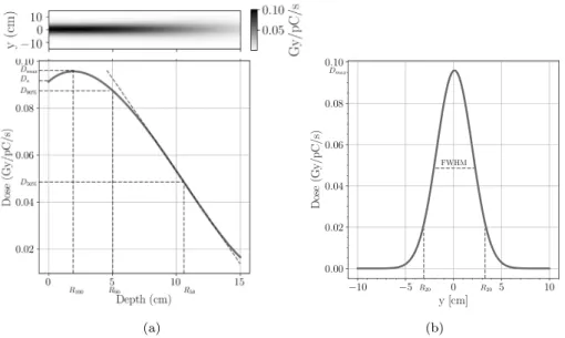
Fig. 4. The absorbed dose characteristics of the unconditioned electron beam; (a) the dose distribution map and depth dose curve with dosimetric characteristics: the dose maximum 𝐷𝑚𝑎𝑥= 9.7 cGy∕pC∕sat depth of 1.93 cm; the therapeutic range𝑅90= 5 cmdefined as the depth where the absorbed dose equals 90% of𝐷𝑚𝑎𝑥. (b) the transverse dose profile at the depth of dose maximum with the full width at half maximum FWHM=4 cm.
the SYLOS II laser system at ELI-ALPS, which is an ultrastable system), on the basis of which we can confidently state that the 1 kHz LWFA- based electron beams have a high potential for radiobiological and/or radiotherapy applications.
Fig. 4a presents the absorbed dose map and the corresponding central depth dose curve, which has a shape typical of electron beams.
The entrance dose or surface dose (𝐷𝑠) is stated at0.5 mmdepth and is 0.091 Gy∕pC∕s, which represents 94% of𝐷𝑚𝑎𝑥 (which is generally between 90% and 100% for electron energies above 10 MeV) [32]. The initial rise of the curve is due to the increasing electron fluence with depth, determined by the increasing mean incident angles as a result of electron scattering. The absorbed dose continues to increase until the outgoing electrons from an elementary volume are compensated with the electrons leaving that volume (i.e. electronic equilibrium is assured). At this point the depth dose curve becomes relatively flat until electrons leave the beam and the curve begins to fall at a rate depending on the initial beam energy. Our simulated depth dose curve reaches a dose maximum of𝐷𝑚𝑎𝑥= 0.097 Gy∕pC∕sat a depth of𝑅100= 1.93 cm.
The depth of dose maximum and the shape of the curve around this depth are determined by the balance of scatter effects and electron loss, therefore it depends on beam energy and scattering conditions (irradiation geometry, field size and shape, accelerator head design etc.). The therapeutic range, defined as the depth where the absorbed dose equals 90% of𝐷𝑚𝑎𝑥(𝐷90%) represents a relatively uniform dose region which can be used effectively for practical applications. In our case the therapeutic range is around 5 cm.
The distal part of the curve is described by the dose gradient, which is steeper for low energies and becomes less steep as the energy increases. In practice, this distal part of the depth dose curve can also be described by the depth (𝑅50) where the depth dose becomes half of the maximum (𝐷50%). However, this characteristic is significantly affected by the components of accelerators as well as by the medium in which the electrons propagate.
The simulated electron beam at the focal point has a diameter of 0.3 μmin the transverse plane and has a bunch length of20 μm. The divergence angle is 0.9◦, which results in a beam size of 3.14 cm at 100 cm source to surface distance at FWHM (Fig. 4a), which grows to 4.1 cm at the depth of dose maximum (Fig. 4b). This electron beam produces a dose distribution having a transverse profile with a high central dose, which rapidly falls forming non-uniform transverse dose distribution. This significantly affects the usability of the beam.
The above results were obtained using the electron beam parameters taken from the PIC simulation, which describe the electron bunch right after it exits the plasma medium. However, the electron beam suffers changes during propagation toward the irradiation target. These changes strongly correlate with the design and components of the accelerator and affect both dose distribution and the usability of the beam. In this raw form, this electron beam exhibits favorable properties for radiotherapy, but further beam preparations maybe needed for real applications. The geometrical properties (field shape and dimensions) are too large for pencil beam irradiation techniques, and too small for conventional techniques that usually require square fields measuring up to25 cm × 25 cm. Such fields can be achieved using either a dual scattering foil system or the spot scanning technique. The former is the most common technique used in LINAC based radiotherapy systems due to its reliability.
A dual scattering foil consists of a scatterer foil and a second flatten- ing foil. The former is made from a material with a high atomic number, and it has an optimal thickness which produces the desired scattering effect. The second foil is made from a material with a low atomic number, it has a conical shape and is designed to flatten the scattered beam. When designing such a system one needs to consider the size and flatness of the obtained beam as well as the decrease in the number of electrons, the degradation of the energy spectrum (broadening and shifting toward the lower energies) and the Bremsstrahlung photon contamination. However, even a carefully designed system may suffer from beam degradation, which can be compensated by the adjustment of the incoming beam parameters (particle numbers, energy, etc.)
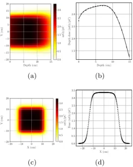
We performed several simulations to estimate the feasibility of this solution, although the development of a dual scattering foil system is beyond the scope of this paper. Using an Au foil as the scattering foil and a conical Al foil as the flattening foil, together with a rectangular diaphragm to collimate the beam to the desired shape we obtained a rough estimate of the dose rate. The dose rate obtained for two beams with fields of15 cm×15 cmand20 cm×20 cmis1.1mGy∕pC∕sat a depth of 1.8 cm and 0.9 mGy/pC/s at a depth of 2.2 cm, respectively. From these preliminary results we can conclude that this solution cannot be applied to our case without the need to significantly increase the pulse charge.
In contrast, the scanning beam technique seems to be a viable alternative to produce larger field sizes. Based on our MC simulations, we can demonstrate that with the available dose rate obtained with 1 pC pulse charge, the spot scanning system can produce a beam size
Fig. 5. Dose map, depth dose curve and dose profile at maximum dose depth, obtained with the spot scanning technique. The dose distribution was obtained by summing as many beams as necessary to produce a20 cm × 20 cmsquare beam. InFig. 5it can be observed that the therapeutic range is enlarged, due to electronic equilibrium which is only partially realized in case of the original beam.
of20 cm × 20 cmin a few tens of milliseconds, with a central axis depth dose of about 0.275 mGy at the depth of dose maximum. This means, that the dose rate which can be achieved with spot scanning method is 1.65 Gy/min/pC. Considering the pulse charge of 3 pC, obtained from PIC simulations, the dose rate improves to a modest but usable value of 4.95 Gy/min. These results were obtained by simulating the spot scanning technique using the previously generated depth dose data.
Fig. 5presents the dose maps, the depth dose curve and profile at the depth of dose maximum for a beam field of20 cm × 20 cm. As it can be seen, both the beam width, and the therapeutic range are enlarged, and dose profile homogeneity also improves due to the increased field size.
The spot scanning technique offers beams with less Bremsstrahlung contamination and without energy spectra broadening. Scanning beam techniques generally produce a deeper therapeutic range and steeper fall-off when compared with the scattering foil method. Furthermore, in the conventional electron beam therapy usually individually shaped, irregular fields are needed, therefore the spot scanning technique would be a possible solution. However, this technique assumes more complex technical solutions, which increases the possibilities of errors. For this reason, this technique is not preferred in clinical accelerators.
4. Conclusion
Laser driven electron acceleration represents a long-awaited break- through in the development of novel radiotherapy facilities. The feasi- bility and suitability of real particle beam parameters can be investi- gated using currently available high-power laser systems.
Electron beams produced in plasma by a 1 kHz high repetition rate laser system may provide a promising alternative for conventional accelerators. In this study we have shown that this laser system can produce electron beams with high energies (35.97 MeV mean kinetic energy) and acceptable dose rates (18 Gy/min considering the electron bunch charge of 3 pC obtained by PIC simulations) and doses delivered with very high precision, due to the high repetition rate of the system.
Our results suggest that this LWFA acceleration technique can be a promising alternative for RF-based conventional LINAC electron accel- erators. The beam energy and charge can be controlled by modifying
the target length and plasma density via changing the gas jet pressure, even during the operation. This will enable researchers to perform intensity and energy modulated irradiation. The energy modulation and the spot scanning technique together could open extremely important application spectra for electron irradiation of superficial targets with uneven thickness, providing significant normal tissue protection.
Moreover, theoretical studies suggest several possible novel appli- cations of the presented LWFA system. Due to the small divergence of the beam, it is relatively easy to further narrow the beam and produce pencil beams for spot scanning techniques. Furthermore, we see the possibility of producing so-called microbeams, which are extensively researched due to their improved therapeutic effects.
The mean bunch length (pulse duration) of an electron shot is 2 ps at 100 cm from the source, which leads to an instantaneous dose rate of an electron shot with 1 pC charge of6 × 105 Gy∕s. This very high instantaneous dose rate can open a new avenue to studying the so- called FLASH effects where the ultrahigh instantaneous dose rate can substantially enhance the therapeutic window [14–16]. However, it is important to note that the conditions to produce the FLESH effect are not clearly defined in the literature. It seems that the instantaneous dose rate may be one of the conditions, however, the repetition rate must be not too high to mitigate the oxygen scavenging effect of a high dose rate (see Wilson et al. [16]).
As we can see, there are many possibilities as well as issues to be solved prior to real applications. Our in silico study represents a promising start for further scientific work on laser driven electron source development. As soon as the experimental facility is assured, intensive work is planned to find the best beam steering solution, to develop the suitable beam monitoring and dosimetry system and to realize the necessary technical conditions for the first radiobiological experiments.
CRediT authorship contribution statement
R. Polanek:Conceptualization, Methodology, Software, Visualiza- tion, Investigation, Writing - original draft.Nasr A.M. Hafz:Conceptu- alization, Validation, Supervision, Writing - review & editing.Zs. Lécz:
Software, Validation.D. Papp:Conceptualization, Validation, Super- vision.C. Kamperidis:Conceptualization, Supervision. Sz. Brunner:
Resources.E.R. Szabó:Resources.T. Tőkés:Project administration.K.
Hideghéty:Conceptualization, Supervision.
Declaration of competing interest
The authors declare that they have no known competing finan- cial interests or personal relationships that could have appeared to influence the work reported in this paper.
Acknowledgments
This work was supported in part by the European Union and co- financed by the European Regional Development Fund through the ELI-ALPS project (GINOP-2.3.6-15-2015-00001), and in part by Hori- zon 2020, the EU Framework Programme for Research and Innovation under Grant Agreement No. 654148 and No. 871124 Laserlab-Europe.
N. A. M. H. acknowledges the President International Fellowship Initiative (PIFI) of the Chinese Academy of Sciences; the Interna- tional Partnership Program (181231KYSB20170022) of CAS; the Inter- Governmental Science and Technology Cooperation of MOST.
References
[1] K.R. Hogstrom, P.R. Almond, Review of electron beam therapy physics, Phys.
Med. Biol. 51 (13) (2006) R455–R489,http://dx.doi.org/10.1088/0031-9155/
51/13/r25.
[2] T. Tajima, J.M. Dawson, Laser electron accelerator, Phys. Rev. Lett. 43 (4) (1979) 267–270,http://dx.doi.org/10.1103/physrevlett.43.267.
[3] A.J. Gonsalves, K. Nakamura, J. Daniels, C. Benedetti, C. Pieronek, T.C.H.
de Raadt, S. Steinke, J.H. Bin, S.S. Bulanov, J. van Tilborg, C.G.R. Geddes, C.B.
Schroeder, C. Tóth, E. Esarey, K. Swanson, L. Fan-Chiang, G. Bagdasarov, N.
Bobrova, V. Gasilov, G. Korn, P. Sasorov, W.P. Leemans, Petawatt laser guiding and electron beam acceleration to 8 gev in a laser-heated capillary discharge waveguide, Phys. Rev. Lett. 122 (8) (2019) 084801,http://dx.doi.org/10.1103/
physrevlett.122.084801.
[4] J. Wenz, A. Döpp, K. Khrennikov, S. Schindler, M.F. Gilljohann, H. Ding, J.
Götzfried, A. Buck, J. Xu, M. Heigoldt, W. Helml, L. Veisz, S. Karsch, Dual-energy electron beams from a compact laser-driven accelerator, Nature Photonics 13 (4) (2019) 263–269,http://dx.doi.org/10.1038/s41566-019-0356-z.
[5] S. Li, G. Li, Q. Ain, M.S. Hur, A.C. Ting, V.V. Kulagin, C. Kamperidis, N.A.M.
Hafz, A laser-plasma accelerator driven by two-color relativistic femtosecond laser pulses, Sci. Adv. 5 (11) (2019) eaav7940,http://dx.doi.org/10.1126/sciadv.
aav7940.
[6] R. Budrinas, T. Stanislauskas, J. Adamonis, A. Aleknavičius, G. Veitas, D.
Gadonas, S. Balickas, A. Michailovas, A. Varanavičius, 53 w average power cep- stabilized opcpa system delivering 55 tw few cycle pulses at 1 khz repetition rate, Opt. Express 25 (5) (2017) 5797,http://dx.doi.org/10.1364/oe.25.005797.
[7] M. Bazalova-Carter, B. Qu, B. Palma, B. Hårdemark, E. Hynning, C. Jensen, P.G. Maxim, B.W. Loo, Treatment planning for radiotherapy with very high- energy electron beams and comparison of VHEE and VMAT plans: Treatment planning for VHEE radiotherapy, Med. Phys. 42 (5) (2015) 2615–2625,http:
//dx.doi.org/10.1118/1.4918923.
[8] C. DesRosiers, V. Moskvin, M. Cao, C.J. Joshi, M. Langer, Laser-plasma generated very high energy electrons in radiation therapy of the prostate, Proc. SPIE 6881 (2008) 688109,http://dx.doi.org/10.1117/12.761663.
[9] E. Schueler, K. Eriksson, E. Hynning, B. Loo, P. Maxim, TU-H-BRC-03: Evaluation of very high-energy electron (VHEE) beams in comparison to VMAT and PBS treatment plans, Med. Phys. 43 (6Part36) (2016) 3766,http://dx.doi.org/10.
1118/1.4957610.
[10] B. Palma, M. Bazalova-Carter, B. Hårdemark, E. Hynning, B. Qu, B.W. Loo, P.G. Maxim, Assessment of the quality of very high-energy electron radiotherapy planning, Radiother. Oncol. 119 (1) (2016) 154–158,http://dx.doi.org/10.1016/
j.radonc.2016.01.017.
[11] S. N. A. Laboratory, Next linear collider test accelerator, URL:https://portal.slac.
stanford.edu/sites/ard_public/facet/newnav/Pages/tf/nlcta/whatis.aspx.
[12] A. Giulietti (Ed.), Laser-Driven Particle Acceleration Towards Radiobiology and Medicine, in: Biological and Medical Physics, Biomedical Engineering, Springer International Publishing, 2016,http://dx.doi.org/10.1007/978-3-319-31563-8.
[13] A. Giulietti, G. Bussolino, L. Fulgentini, P. Koester, L. Labate, L.A. Gizzi, Laser- plasma particle sources for biology and medicine, in: Progress in Ultrafast Intense Laser Science XII, Springer International Publishing, 2015, pp. 151–178, http://dx.doi.org/10.1007/978-3-319-23657-5_8.
[14] M. Durante, E. Brauer-Krisch, M. Hill, Faster and safer? Flash ultra-high dose rate in radiotherapy, Br. J. Radiol. 91 (1082) (2017) 20170628,http://dx.doi.
org/10.1259/bjr.20170628.
[15] M.-C. Vozenin, J. Hendry, C. Limoli, Biological benefits of ultra-high dose rate flash radiotherapy: Sleeping beauty awoken, Clin. Oncol. 31 (7) (2019) 407–415, http://dx.doi.org/10.1016/j.clon.2019.04.001.
[16] J.D. Wilson, E.M. Hammond, G.S. Higgins, K. Petersson, Ultra-high dose rate (FLASH) radiotherapy: Silver bullet or fool’s gold?, Front. Oncol. 9 (nil) (2020) nil,http://dx.doi.org/10.3389/fonc.2019.01563.
[17] O. Lundh, J. Lim, C. Rechatin, L. Ammoura, A. Ben-Ismaïl, X. Davoine, G. Gallot, J.-P. Goddet, E. Lefebvre, V. Malka, J. Faure, Few femtosecond, few kiloampere electron bunch produced by a laser-plasma accelerator, Nat. Phys. 7 (3) (2011) 219–222,http://dx.doi.org/10.1038/nphys1872.
[18] A. Ogata., T. Kondoh, J. Yang, A. Yoshida, Y. Yoshida, Lwfa of atto-second and femto-second bunches for pulse radiolysis, Internat. J. Modern Phys. B 21 (03n04) (2007) 447–458,http://dx.doi.org/10.1142/s0217979207042239.
[19] A.R. Maier, N.M. Delbos, T. Eichner, L. Hübner, S. Jalas, L. Jeppe, S.W. Jolly, M.
Kirchen, V. Leroux, P. Messner, M. Schnepp, M. Trunk, P.A. Walker, C. Werle, P. Winkler, Decoding sources of energy variability in a laser-plasma accelera- tor, Phys. Rev. X 10 (2020) 031039,http://dx.doi.org/10.1103/PhysRevX.10.
031039.
[20] N.A.M. Hafz, T.M. Jeong, I.W. Choi, S.K. Lee, K.H. Pae, V.V. Kulagin, J.H. Sung, T.J. Yu, K.-H. Hong, T. Hosokai, J.R. Cary, D.-K. Ko, J. Lee, Stable generation of gev-class electron beams from self-guided laser-plasma channels, Nature Photonics 2 (9) (2008) 571–577,http://dx.doi.org/10.1038/nphoton.2008.155.
[21] D. Guénot, D. Gustas, A. Vernier, B. Beaurepaire, F. Böhle, M. Bocoum, M.
Lozano, A. Jullien, R. Lopez-Martens, A. Lifschitz, J. Faure, Relativistic electron beams driven by khz single-cycle light pulses, Nature Photonics 11 (5) (2017) 293–296,http://dx.doi.org/10.1038/nphoton.2017.46.
[22] M. Ouillé, A. Vernier, F. Böhle, M. Bocoum, A. Jullien, M. Lozano, J.-P. Rousseau, Z. Cheng, D. Gustas, A. Blumenstein, P. Simon, S. Haessler, J. Faure, T. Nagy, R. Lopez-Martens, Relativistic-intensity near-single-cycle light waveforms at khz repetition rate, Light: Sci. Appl. 9 (1) (2020) 47, http://dx.doi.org/10.1038/
s41377-020-0280-5.
[23] S. Agostinelli, J. Allison, K. Amako, J. Apostolakis, H. Araujo, P. Arce, M. Asai, D.
Axen, S. Banerjee, G. Barrand, F. Behner, L. Bellagamba, J. Boudreau, L. Broglia, A. Brunengo, H. Burkhardt, S. Chauvie, J. Chuma, R. Chytracek, G. Cooperman, G. Cosmo, P. Degtyarenko, A. Dell’Acqua, G. Depaola, D. Dietrich, R. Enami, A.
Feliciello, C. Ferguson, H. Fesefeldt, G. Folger, F. Foppiano, A. Forti, S. Garelli, S. Giani, R. Giannitrapani, D. Gibin, J.G. Cadenas, I. González, G.G. Abril, G.
Greeniaus, W. Greiner, V. Grichine, A. Grossheim, S. Guatelli, P. Gumplinger, R. Hamatsu, K. Hashimoto, H. Hasui, A. Heikkinen, A. Howard, V. Ivanchenko, A. Johnson, F. Jones, J. Kallenbach, N. Kanaya, M. Kawabata, Y. Kawabata, M.
Kawaguti, S. Kelner, P. Kent, A. Kimura, T. Kodama, R. Kokoulin, M. Kossov, H.
Kurashige, E. Lamanna, T. Lampén, V. Lara, V. Lefebure, F. Lei, M. Liendl, W.
Lockman, F. Longo, S. Magni, M. Maire, E. Medernach, K. Minamimoto, P.M.
de Freitas, Y. Morita, K. Murakami, M. Nagamatu, R. Nartallo, P. Nieminen, T. Nishimura, K. Ohtsubo, M. Okamura, S. O’Neale, Y. Oohata, K. Paech, J.
Perl, A. Pfeiffer, M. Pia, F. Ranjard, A. Rybin, S. Sadilov, E.D. Salvo, G. Santin, T. Sasaki, N. Savvas, Y. Sawada, S. Scherer, S. Sei, V. Sirotenko, D. Smith, N.
Starkov, H. Stoecker, J. Sulkimo, M. Takahata, S. Tanaka, E. Tcherniaev, E.S.
Tehrani, M. Tropeano, P. Truscott, H. Uno, L. Urban, P. Urban, M. Verderi, A.
Walkden, W. Wander, H. Weber, J. Wellisch, T. Wenaus, D. Williams, D. Wright, T. Yamada, H. Yoshida, D. Zschiesche, Geant4-a simulation toolkit, Nucl. Instrum.
Methods Phys. Res. A 506 (3) (2003) 250–303,http://dx.doi.org/10.1016/s0168- 9002(03)01368-8.
[24] J. Allison, K. Amako, J. Apostolakis, H. Araujo, P.A. Dubois, M. Asai, G. Barrand, R. Capra, S. Chauvie, R. Chytracek, G. Cirrone, G. Cooperman, G. Cosmo, G.
Cuttone, G. Daquino, M. Donszelmann, M. Dressel, G. Folger, F. Foppiano, J.
Generowicz, V. Grichine, S. Guatelli, P. Gumplinger, A. Heikkinen, I. Hrivnacova, A. Howard, S. Incerti, V. Ivanchenko, T. Johnson, F. Jones, T. Koi, R. Kokoulin, M. Kossov, H. Kurashige, V. Lara, S. Larsson, F. Lei, O. Link, F. Longo, M.
Maire, A. Mantero, B. Mascialino, I. McLaren, P.M. Lorenzo, K. Minamimoto, K.
Murakami, P. Nieminen, L. Pandola, S. Parlati, L. Peralta, J. Perl, A. Pfeiffer, M.
Pia, A. Ribon, P. Rodrigues, G. Russo, S. Sadilov, G. Santin, T. Sasaki, D. Smith, N. Starkov, S. Tanaka, E. Tcherniaev, B. Tome, A. Trindade, P. Truscott, L. Urban, M. Verderi, A. Walkden, J. Wellisch, D. Williams, D. Wright, H. Yoshida, Geant4 developments and applications, IEEE Trans. Nucl. Sci. 53 (1) (2006) 270–278, http://dx.doi.org/10.1109/tns.2006.869826.
[25] J.S. Coursey, D.J. Schwab, J.J. Tsai, R.A. Dragoset, Atomic Weights and Isotopic Compositions with Relative Atomic Masses, NIST Physical Measurement Lab- oratory Web Page, 2015, URL: https://www.nist.gov/pml/atomic-weights-and- isotopic-compositions-relative-atomic-masses.
[26] T.D. Arber, K. Bennett, C.S. Brady, A. Lawrence-Douglas, M.G. Ramsay, N.J. Sir- combe, P. Gillies, R.G. Evans, H. Schmitz, A.R. Bell, C.P. Ridgers, Contemporary particle-in-cell approach to laser-plasma modelling, Plasma Phys. Control. Fusion 57 (11) (2015) 113001,http://dx.doi.org/10.1088/0741-3335/57/11/113001.
[27] R. Lehe, A. Lifschitz, C. Thaury, V. Malka, X. Davoine, Numerical growth of emittance in simulations of laser-wakefield acceleration, Phys. Rev. ST Accel.
Beams 16 (2013) 021301,http://dx.doi.org/10.1103/PhysRevSTAB.16.021301, URL:https://link.aps.org/doi/10.1103/PhysRevSTAB.16.021301.
[28] Geant4 Book For Application Developers, Online book, 2019, URL:http://geant4- userdoc.web.cern.ch/geant4-userdoc/UsersGuides/ForApplicationDeveloper/
html/index.html.
[29] S.P.D. Mangles, C.D. Murphy, Z. Najmudin, A.G.R. Thomas, J.L. Collier, A.E.
Dangor, E.J. Divall, P.S. Foster, J.G. Gallacher, C.J. Hooker, D.A. Jaroszynski, A.J. Langley, W.B. Mori, P.A. Norreys, F.S. Tsung, R. Viskup, B.R. Walton, K.
Krushelnick, Monoenergetic beams of relativistic electrons from intense laser- plasma interactions, Nature 431 (7008) (2004) 535–538,http://dx.doi.org/10.
1038/nature02939.
[30] J. Faure, Y. Glinec, A. Pukhov, S. Kiselev, S. Gordienko, E. Lefebvre, J.-P.
Rousseau, F. Burgy, V. Malka, A laser-plasma accelerator producing monoen- ergetic electron beams, Nature 431 (7008) (2004) 541–544,http://dx.doi.org/
10.1038/nature02963.
[31] C.R. Geddes, C. Toth, J. van Tilborg, E. Esarey, C.B. Schroeder, D. Bruhwiler, C. Nieter, J. Cary, W.P. Leemans, High-quality electron beams from a laser wakefield accelerator using plasma-channel guiding, Nature 431 (7008) (2004) 538–541,http://dx.doi.org/10.1038/nature02900.
[32] H. Svensson, P. Almond, A. Brahme, A. Dutreix, H.K. Leetz, Report 35, J. Int.
Comm. Radiat. Units Meas. os18 (2) (1984) NP,http://dx.doi.org/10.1093/jicru/
os18.2.report35.