10
A Stern-Gerlach Experiment on Polarized Neutrons*
J . E. SHERWOOD, T. E. STEPHENSON, and SEYMOUR BERNSTEIN Oak Ridge National Laboratory, Oak Ridge, Tennessee
I n t r o d u c t i o n
When a beam of neutrons passes through a material body the pro- cess may be considered analogous to the passage of light through a refractive medium. Thus we may define an index of refraction n = V(E — V/E), where E is the energy of a neutron, and V is the average potential energy of the neutron while in the body. If Θ is the glancing angle of incidence, it follows that total reflection will occur for Θ = V(V/É). In other words, all wavelengths greater than
the critical wave length
X
c= ej
^ 2mV will be totally reflected.
In the case of a magnetized iron mirror, the potential energy is V = Vn + Vm, where Vn is that due to the nuclei and Vm = —μ . Ë is the potential energy of the neutron's magnetic moment μ in the average net field ß. Thus, if X+c and X~c are the critical wavelengths for ß parallel to Ë and μ antiparallel to Ë respectively, we have that
X+c > X-c ( B # 0 )
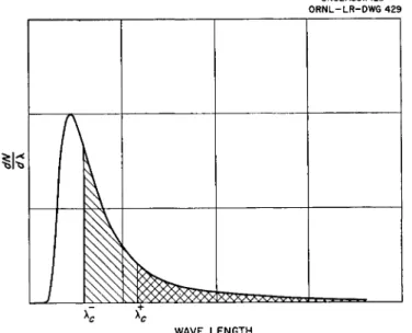
The spectrum of reflected neutrons will therefore have the general appearance shown in Fig. 1 (assuming the spectrum of the incident beam to be Maxwellian). Thus the spin state with μ antiparallel to B is more abundant. Since the gyromagnetic ratio of the neutron is negative,1 the resultant spin of the neutrons in the totally reflected beam is parallel to the applied magnetic field. I t may be noted that the direction of the dominant neutron spin in a beam of
♦Reprinted from Physical Review.
181
polarized neutrons is significant in the interpretation of experi- ments on the interaction of polarized neutron beams with polarized target nuclei.2,3 However, in no other experiments with polarized neutrons has the direction of the neutron spin been of consequence.
Only neutron intensities were involved.
UNCLASSIFIED ORNL-LR-DWG 429
1(1
^fc 1
A X X A A A ^ V V V S WAVE LENGTHFig. 1. Intensity distribution of neutrons reflected from magnetized iron mirror.
For μ parallel to B, λ > A+c. For μ anti-parallel to B, X> X~e.
In order to check the results of the above argument in a very direct manner, we have done a Stern-Gerlach type of experiment in which a beam of polarized neutrons is deflected magnetically. This experiment is described below.
Description of the Apparatus
The mirror was of soft iron, about If in. x 6 in. long and was magnetized parallel to the face in a direction perpendicular to the length and to the neutron beam. The exit edge of the mirror was rounded off so that the magnetic field in this region would change less abruptly. It was felt that this procedure would partially alleviate the depolarization effects found by early experimenters. The glancing angle of the neutron beam upon the mirror was approximately 3.10"3 radians.
The slot-wedge type of deflecting field was felt to give the highest gradient consistent with reasonable cost. Since this arrangement had
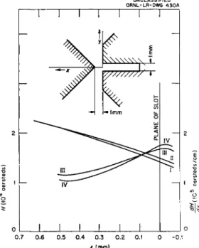
A STERN-GERLACH EXPERIMENT 183 been thoroughly investigated by the early molecular beam experi- menters,4 the cross section of their magnet gap was copied. Fig. 25 describes the cross section and magnetic characteristics of the gap ; the length chosen was 1 meter. The average field in our magnet gap was found to be about 20,000 Oersteds by means of a bismuth wire measure- ment. Energy for the gap was provided by four large solenoids of about 13,000 ampere turns each.
UNCLASSIFIED ORNL-LR-DWG 430A
0.4 0.3 0.2 J L
x (mm)
Fig. 2. Field strength and inhomogeneity of magnetic field in gap (ref. 5) : Curve I: Field strength in the plane of symmetry. Curve II: Field strength of 0.2 mm outside plane of symmetry. Curve III : Inhomogeneity in the plane of
symmetry. Curve IV: Inhomogeneity 0.2 mm outside plane of symmetry.
The detector was a conventional arrangement consisting of a well- shielded BF3 counter of about 1 in. diameter and 8 in. long. Its efficiency was about 90% for the reflected neutrons. Standard ampli- fiers and a scale-of-64 registers were used. Background was 1.6 counts/min.
Even with a gradient of the order of 105 Oersted/cm extended over a length of a meter, the deflections produced are inconveniently small.
This, together with the difficulty of producing such a gradient over a large space, requires a very high degree of collimation, in order to ensure that only those neutrons which spend an appreciable length
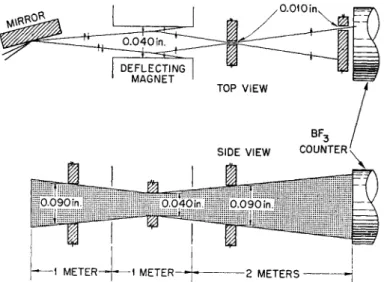
of time in the region of high gradient will be counted. This was achieved, as shown in Fig. 3, by a combination of cadmium shts and holes. The main collimation was provided by the 0.010 in. vertical slit at the exit end of the deflecting magnet. It is easily seen that this location of the slit does not complicate the interpretation of the results and leads to much better collimation than is obtained with the slit preceding the deflecting magnet.
UNCLASSIFIED DWG. 22659
0.01 Oiru
Fig. 3. Schematic d i a g r a m of b e a m collimation system showing typical trajec- tories a n d vertical slits (top view) a n d horizontal slits (side view).
Procedure
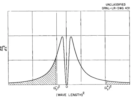
The two spin-states will suffer opposite forces in the deflecting magnet so that, with perfect collimation and infinitely good resolution, one should obtain an intensity distribution in the beam as shown in Fig. 4. (Displacement is proportional to λ2.)
In practice, however, a 0.010 in. slit is translated across the face of the detector and yields the result shown in Fig. 5. For comparative purposes, undeflected and deflected-depolarized beams are shown there also. The depolarization was accomplished by interposing a soft iron shim in the beam between the mirror and the deflecting magnet, at a place where the magnetic field was small.
The experiment was repeated under conditions in which the neutron spins were "flipped" relative to the magnetic field, during their passage
A STERN-GERLACH EXPERIMENT 185
UNCLASSIFIED ORNL-LR-DWG 431
1
^ ^ ^
H
(WAVE LENGTH)
(Xt)2
Fig. 4. Expected deflection pattern for infinite resolving power and perfect collimation. Shaded areas are derived from Fig. 1.
8 0 0
7 0 0
6 0 0
5 0 0
4 0 0
3 0 0
2 0 0
100
UNCLASSIFIED DWG. 22663 1 1 1 1 1 1 1 —
Δ UNDEFLECTED BEAM (15 min PER POINT)
© POLARIZED BEAM (30min PER POINT) Ξ DEPOLARIZED BEAM ( 3 0 min PER POINT)
1.180 1.200 1.220 1.240 1.260
DETECTOR POSITION (in.)
1.280 1.300
Fig. 5. Experimentally observed deflection patterns. Inset shows orientation of pole-pieces with respect to the intensity pattern.
N
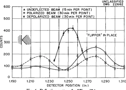
from the mirror to the deflecting magnet. This spin reversal was brought about by means of an arrangement of permanent magnets and pole pieces which caused the field to reverse its direction in a distance short compared with the Larmor precession distance. An intensity- displacement run then yielded the result shown in Fig. 6, in which it is seen that the main portion of the beam is now deflected to the right, instead of to the left.
6 0 0
5 0 0
4 0 0
I 300
o o
2 0 0
100
UNCLASSIFIED DWG. 2 2 6 6 2
u
1 H
f i
Δ UNDEFLECTED BEAM (15min PER POINT)
® POLARIZED BEAM ( 3 0 min PER POINT) Θ DEPOLARIZED BEAM ( 3 0 min PER POINT)
<É
-~-\
r ^ /
^ N
\
^^
<
<^
\y\
y
'FLIPP
)
ER" IN PLACE
1 VL X
F — Ί Γ
1.190 1.210 1.230 1.250 1.270 1.290 DETECTOR POSITION (in.)
Fig. 6. Deflection pattern for "flipped" beam.
1.310
Interpretation of Results
If we consider only the normal pattern, Fig. 5, and agree to take directions to the right as a positive X-axis, the following argument applies: The energy of the dipole is W = —μ·β= —(μ· 13)Η, where Ü is a unit vector in the direction of the magnetic field ff, and H is the magnitude of the field. Then Fx = - (dWjdx) = (μ-8) (dH/dx).
By inspection of Fig. 5, it is seen that Fx < 0 and (dH/dx) > 0. It follows that μ ·· Û < 0. Thus the experiment shows directly that the resultant spin in a neutron beam polarized by reflection from mag- netized iron is parallel to the magnetic field applied to the mirror.
From this it can be shown that the nuclear and magnetic scattering amplitudes (for iron) are of the same sign when the neutron spin and electronic spin are oppositely directed, and conversely.
By means of double transmission experiments, the resultant spin direction in the totally reflected beam from a magnetized iron mirror
A STERN-GERLAGH EXPERIMENT 187
was compared with the resultant spin direction produced by trans- mission through magnetized polycrystalline iron. We find that for a sample magnetized perpendicular to the neutron velocity, the resultant neutron spins are directed opposite to the applied magnetic field. In the case of a single crystal of magnetite, in which the magnetic field was applied perpendicular to the scattering plane, the resultant spin in a beam reflected from the 220 planes was found6 to be opposite to the applied magnetic field also.
Acknowledgement
We are very grateful to Professor J. M. Jauch for numerous helpful discussions.
R E F E R E N C E S
1 P. N. Powers, Phys. Rev. 54, 827 (1938).
1 Bernstein, Roberts, Stanford, Dabbs, and Stephenson, Phys. Rev. (June 1, 1954).
8 Roberts, Bernstein, Dabbs, and Stanford, Phys. Rev. (July 1, 1954).
4 I. Estermann and O. Stern, Z- Physik 85, 17 (1933).
* Ibid., p. 18.
« G. G. Shull, Phys. Rev. 81, 626 (1951).