Time-of-Flight Methods in Low Energy Neutron Cross Section Measurements at the MTR
R. G . FLUHARTY and J. E. EVANS"1"
Phillips Petroleum Company, Atomic Energy Division, Idaho Falls, Idaho
T he neutron cross section program at t he M T R was initiated on advice of t he Nuclear Cross Section Advisory G r o up i n order to take advantage of t he high flux of t he M T R to provide cross section measurements of interest to reactor physics. T h is survey discussion of this program wil l involve a mixture of four phases as follows:
(1) Major emphasis wil l be placed u p on time-of-flight techniques which have been used at t he M T R a nd which should be of general interest. T h is part of t he discussion is only suggestive of t he many possible experiments.
(2) A comparison wil l be made between t he M T R as an experi- mental reactor neutron source a nd t he linear accelerators, as well as other reactors.
(3) Highlights of recent cross section results of t he M T R wil l be used for illustration where appropriate.
(4) Some discussion of t he programs which are u n d er way or are to be undertaken, including some discussion of t he systematic approach involved.
A s a high flux experimental neutron source t he M T R is still competitive wit h other research reactors after 9 years of operation.
Since t he M T R fast chopper is similar to those designed by Seidl1 at Brookhaven, a comparison wit h other installations having Brook- haven choppers should be valid. T he chopper at t he M T R provides a neutron intensity which is a factor of about 10 greater than that from t he chopper at t he B N L research reactor. M o re recently a similar chopper has been placed i n operation at t he N R U reactor at Chalk River; t he intensity is a factor of about 80 greater than that at t he B N L reactor. On this basis, t he chopper at t he Chalk River installation has a higher intensity t h an t he M T R by a factor of 8 to 10.
* Work done under the auspices of the U . S. Atomic Energy Commission, t Present address: Lockheed Aircraft Company, Palo Alto, California.
35
36 R. G. FLUHARTY AND J. E. EVANS
T he M T R intensity increase of a factor of 10 above the Brook- haven level was somewhat of a disappointment. Expectations were that the intensities would go as the reactor thermal fluxes which differ roughly by a factor of 100 to 200. However, the 1/2?
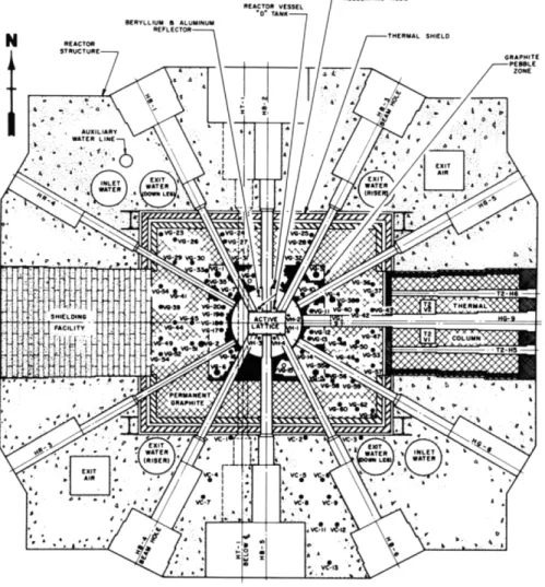
spectra was not found to be in this ratio due to geometrical factors involved i n the beam holes and the small volume of the M T R .2 T h is is illustrated in Fig. 1 where it is seen that the H B -6 beam hole at the corner of the active lattice ends 6 inches away from the 9-inch X 27-inch active lattice. T he thermal flux peaks in the beryllium reflector, b ut the 1 /2? flux does not peak and instead falls off very rapidly. T he thermal to 1 /2? s p e c t r um ratio is ~ 1 /64.
I n Fig. 1 it is of interest to point out that the M T R crystal spectro- meter occupies H B - 4, the velocity selector H G - 6, and the cold neutron facility H G - 5. T he intensity of neutrons available for the velocity selector could be improved by a factor of 10 or greater if moved to a major beam hole.
For beam source purposes the M T R would be equal to any research reactor if redesigned to optimize the core for beam opera- tion. Ideally the fuel should be placed around the source ends of the beams. T he spectrometer should only view the moderator wit h a reasonably high mass n u m b er to improve the 1 /2? spectrum. U n d er these conditions a gain of a factor of 10 to 50 in the 1/2? spectrum could easily be realized.
A s originally conceived, the M T R was designed for 3 0 - Mw operation but it is now operated routinely at 40 M w . Studies of 6 0 - Mw operation reveal only a need for added capacity in the cooling system. Since the original conceptual lifetime of the M T R was 10 years, it would appear in order to plan to redesign the internal structure. Design for m a x i m um flux stability for beam source purposes and for inpile irradiations would appear advantageous. U n d er this proposed operation emphasis would be placed u p on careful measurement of flux and control by poison adjustment. T h is sug- gestion is made wit h thought in mind that the E T R, G E T R, M T R , and the A T R would be available for experimental loops for which space would otherwise be required in the M T R .
I n the evolution of the cross section measurement program at the M T R , the tendency has been to use the fast chopper for most cross section measurements, and to use the crystal spectrometer for measurements only where the monochromatic neutron beam is
TIME-OF-FLIGHT METHODS 37 required. T he implication is not intended that the crystal spectro- meters cannot be competitive in resolution and intensity below 10-ev neutron energy, but many experiments and detector systems are not compatible wit h time-of-flight applications and the crystal spectrometer has been occupied wit h such measurements. I n addition, the large multichannel capacity of the chopper provides
FIG. 1. Horizontal cross section of the M T R showing the experimental beam holes.
38 R. G. FLUHARTY AND J. E. EVANS
the convenience of many neutron energies available simultaneously.
T h i s convenience provides advantages in survey measurements and minimizes relative detector instability problems. Considerable change i n the operational procedures would be required u p on the crystal spectrometer to provide equivalent operational advantages. T he crystal spectrometer has been in fairly continuous use in radio- chemical measurements of fission peak to valley ratios3 as a function of neutron energy and in measuring η as a function of energy using a M n S 04 tank to detect the n e u t r o n s .4
T o illustrate the versatility of the chopper multichannel analyzer and a special time-of-flight technique, the U2 33 fission measurements of Moore et al} provide an interesting example. Here various detec- tors were placed at different positions along the flight path and the signals were electronically delayed to provide a c o m m on time scale.
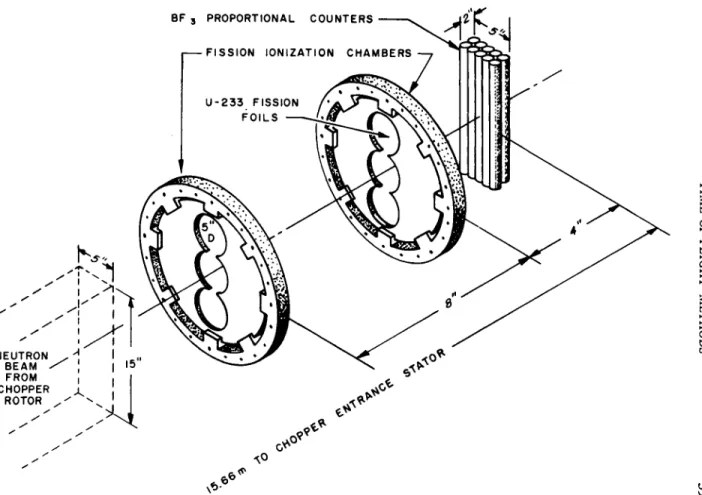
A circuit is required in which the delay is proportional to the time after the chopper burst and is also proportional to the distance between detectors.6* T h is is illustrated in Fig. 2 showing the two banks of fission foil s followed by a bank of B F3 counters. I n the final experiment two B F3 counters were placed horizontally between the fission foils. T he data were taken as follows: T he first fission counter pulses were delayed and mixed wit h those from the second fission counter and t h en transmitted into 256 channels of the 1024-ehannel analyzer. Likewise, the B F3 counter pulses were delayed by one-half the above amount and fed into an alternate 256 channels operating on the same time scale as the fission channels. After approximately 15 minutes of operation a sample was cycled into the beam and the data from the two sets of detectors were recorded in the other two 256 channels. A t the end of the second 15 minutes the sample was removed from the beam and the cycle repeated. I n this m a n n er the s um of measurements involved give a total cross section and fission cross section measurement, and the data are taken on the same energy scale and wit h the same resolution.
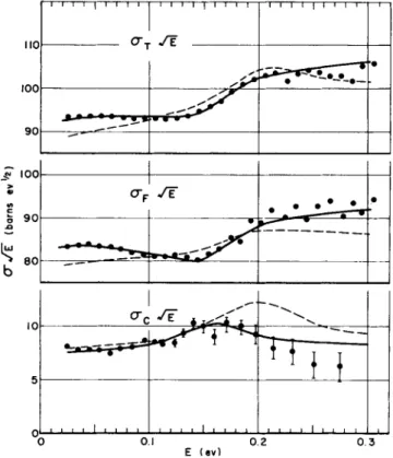
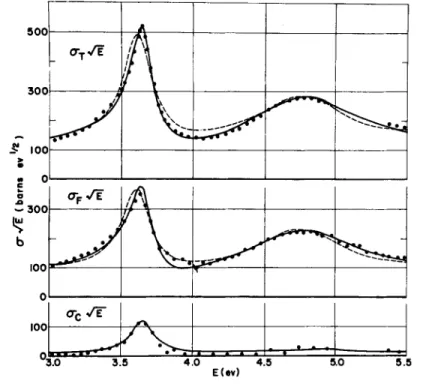
T he importance of such simultaneous data is illustrated in Fig. 3 showing the 0.2-ev resonance of U2 33 giving σρ σ{ and the subtraction (wit h scattering taken out) giving σα. I t is to be noted that the capture cross section is symmetrical ; however, the peak EQ for the resonance does not coincide wit h the peak for af and at. T h is is again illustrated
* This technique is also used for a large bank of B F3 counters to reduce the uncertainty due to counter thickness. At the present a maximum of four delay systems are available.
BF 3 PROPORTIONAL COUNTERS
- F I S S I O N IONIZATION CHAMBERS
FIG. 2. Schematic diagram of fast-chopper fission detectors for U2 33 fission cross section measure- ments. T h e B F
3
counters serve to monitor the beam and are used for total cross section measurements; the first two detectors have electronic time adjustment to give detection times corresponding to the last detector.TIME-OF-FLIGHT METHODS 39
40 R. G. FLUHARTY AND J. E. EVANS
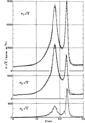
i n Fig. 4 where the more important 1.8- and 2.3-ev resonances are shown. T h e se illustrate the problems involved in combining data wit h slightly different energy scales and resolution for obtaining η(Ε) and oc(E), the neutrons produced per neutron absorbed and the capture to fission ratio, respectively. T h is is also illustrated in Fig. 5 for the 3.7- and the 4.6-ev resonances.
110
100
90
4? 100
90
80
ι ι ι ι I ι ι ι ι
l
1 I 1 I I I ! 1 I l I 1 1 1 1 1 1 ! !τ
SE
0 —Έ ·
•
m
l
ι m fc - γ Τ ^
1 * H "
I I I 1 1 I I 1 1 1 1 1 1 1 1 1 1 1 1 1 1 1 1 1 1 I 1 • 1mm
0.1 E ( e v ) 0.2 0.3
FIG. 3. T h e experimental fission and total cross section of U2 33 in the
vicinity of the 0.2 ev resonance and the derived absorption cross section.
T h e solid line indicates the theoretical multilevel fit in which the neutron width used is essentially of zero magnitude implying that the level is observed because of fission interference effects.
Above these energies subtractions could not be made due to resolution problems involving the thickness of the B F3 counters.
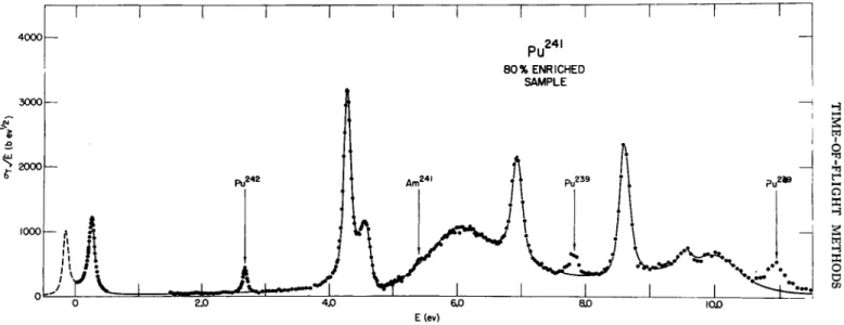
A s a final illustration of the fact that the fission process is considerably
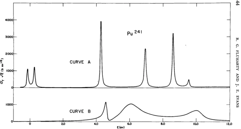
TIME-OF-FLIGHT METHODS 41 different from normal total cross sections, some recent data on P u2 41 taken by Simpson and M o o r e7 are shown in Fig. 6. T he solid line is a multilevel fit to the data which is remarkably good although u n i q u e- ness is not claimed. T he decomposition of the theoretical fit to the data into separate spin states is illustrated in Fig. 7. T he very broad levels interfering wit h the very large asymmetric shapes is dramati-
1500,
1 0 0 0
$ 5 0 0
b O1
5 0 0
3 0 0
£\
:
-
Ρ Â
J
-
[ι F 1 π l Λ
\ u
\
< RF- / F Jt
- ^ c7 1" 1.0
J
IE(EV) 2.0 3.0
FIG. 4. T h e experimental fission and total cross section of U2 33 for the
1.8- and 2.3-ev resonance regions and the derived absorption cross section.
Note the shift in peak cross sections between the three curves emphasizing the need for exact register of instrumental energy calibration and resolution for comparison. T h e solid line shows the theoretical multilevel fit.
42 R. G. FLUHARTY AND J. E. EVANS
500
300
£ 100
>
« 0 c Ik.
ο w 300
b 100
0 100
~3.0 3.5 4.0 4.5 5.0 5.5 E(ev)
FIG. 5. T h e experimental fission and total cross section for U2 33 for the
3.7- and 4.6-ev regions, where the solid line shows the theoretical fit which required two fission channels.
T he intensity of the R PI linear accelerator on a comparative intensity basis using the product of resolution and intensity is better than the present M T R chopper by a factor of ^ 1 5 0, assuming a peak output of 1 018 neutrons/sec and a pulse width of 0.72 sec.
T h i s comparison is based u p on the neutrons per square centimeter intensity at a sample position for an equivalent flight path, and some resolution advantage has been neglected. T he fast chopper is highly competitive if not superior, however, for the small sample applica-
στ/ Ε
Ά
'# \\
Il è
-
ν
cally illustrated in this figure. For fission, the predictions of t e m p e r a- ture coefficients oc and η cannot be made simply on the basis of a single level Breit-Wigner approach. T he ability to unravel the higher energy aspect of these cross sections wil l be enhanced greatly by improved neutron source intensities.
E(ev)
FIG. 6. T h e total cross section of P u2 41 where the solid line shows the multilevel fit assuming one fission channel.
TIME-OF-FLIGHT METHODS43
Ο ΖΟ 4.0 6.0 8.0 ΐαθ 12.0
Ε ( Β Ν)
FIG. 7. T h e theoretical multilevel fit of Fig. 6 decomposed into the spin state assignments. It appears quite probable that assignment of different spin states is required above 2 ev, but below the assignment is arbitrary.
44 R. G. FLUHARTY AND T. E. EVANS
TIME-OF-FLIGHT METHODS 45 tions wherein a very small sample can be placed at the position of m i n i m um beam size. T he M T R fast chopper still has great impor- tance for rare isotope and radioactive samples.
FIG. 8. A schematic diagram of the fast chopper illustrating the provisions incorporated to handle highly radioactive samples.
Provisions which have been made for such samples wit h the fast chopper are shown in Fig. 8. T h is shows a perspective cutaway of the fast chopper housing, giving a visual idea of the shielded sample changer which has been incorporated. T he shielding which has been
46 R. G. FLUHARTY AND J. E. EVANS
provided for in the sample holder is designed for 5 to 10 thousand curies of activity. As a m i n i m um it should be adequate for the 2300 curies which would be required to r un a 0.1-gram sample of P a2 3 3. T he sample changer has been satisfactorily tested using a 600-curie sample of A u1 9 8.
T he results of measurements on A u1 98 by Simpson and S c h u m a n8 account for the t h e r m al cross section of gold. No higher reson- ances have as yet been observed. T h is would indicate that the irradiations of gold wit h c a d m i um covers should produce H g1 98 relatively free from higher isotopes.
T he enormous n u m b er of isotopes potentially available for mea- surement of radioactive samples is shown in Table I. I t tabulates the isotopes or isomers of half-lives greater t h an 1 msec. F or the fast chopper applications it is necessary to have a half-lif e greater t h an 1 day. T he availability of high flux reactors for sample production provides a unique advantage for these applications.
T A B L E I
A TABULATION OF THE NUMBER OF RADIOACTIVE ISOTOPES ACCORDING TO H A L F - L I V E S
Even-•even Even-odd Odd- -even Odd-odd Sub-
total
Sub- total
Sub- total
Sub- total
Stable 170 57 54 9
> 1 year 10 days to
1 year 30 17
200 217
27 50
84 134
27 29
81 110
17 33
26 59 1 day to
10 days 19
236 38
172 35
145 38
97
< 1 day 68 347
160 410
133 352
191 381
Unstable 177 353 298 372
Total 347 410 352 381
Even or odd ~ ~ 7 3 3 ^
Grand total 1490
TIME-OF-FLIGHT METHODS 47 Dr. J o hn Evans, a previous colleague of ours and a co-author of this paper, has studied thermal cross sections as a function of A and finds that there are indeed systematic relationships in the thermal cross sections.9 Several years ago he found that the contours of con- stant thermal cross section values could be drawn t h r o u gh the ther- mal cross sections on a GE type chart plotting Ζ versus N. T h e se curves were improved if a separation of different nuclear species according to their even-even, odd-odd, etc., properties was made.
Contours for decade values of σ were roughly spaced wit h n e u t r o n- rich isotopes having lower absorption cross sections. T h e re were surprisingly few cases where closed contours were necessary, five cases of peaks for X e1 3 2, I n1 3 1, S r9 0, N i6 2, T h2 3 3, and no deep holes.
T he effect of the magic n u m b e rs on the Evans' thermal contours was fairly obvious b ut there were other fairly definite bends in the contours which could not be satisfactorily accounted for at that time. I t is now obvious that the giant resonances in the Γη0/Ο were the cause of these other bends in the curves. Professor J o hn A. Wheeler has suggested that such studies of thermal cross sections may provide some leverage in assessing the influence of the asymmetry t e rm (N — Z)jA on nuclear binding. T he increase from neutron rich to neutron poor isotopes provides possible evidence of such effects.
T o see how this might come about it is well to discuss some of the factors involved in the determination of the thermal cross section.
First, it is fairly obvious that the value of the thermal absorption cross section is dominated by the nearest two resonances, the nearest u n b o u nd positive kinetic energy neutron energy resonances above 0.0253 and the nearest level below which is nearly always a b o u nd level or a negative energy level. T he following factors also should be noted: (a)
r
n°/D
is a smooth function of the atomic weight A, (b) the levels are generally fairly uniformly spaced, and (c) the average spacing adjusted to spin / = 0 is also a smooth function of A or Ν peaked at the magic n u m b e r s. Based on these factors we can u n d e r s t a nd w hy it is possible to draw constant average thermal contours, and to account for few deep holes. On a statistical basis, these factors are sufficient to account for the n u m b er of isotopes wit h thermal cross section values in a given range. However, predictions for a given isotope are only statistical. Resolutions of (N — Z)jA effects from the above factors remains to be determined.T h i s study of available thermal cross section systematics, however, indicates that high thermal cross sections, greater t h an 1000 barns,
48 R. G. FLUHARTY AND J. E. EVANS
are likely to be found wit h a 3 to 1 0% chance among all fairly heavy (A > 70) even-even isotopes. So far littl e data exist for level spacings of even-even isotopes since fast choppers can only cover the energy range in which just a few resonances occur. I t would appear that the linear accelerators can contribute considerably to the systematics of even-even spacings and other systematics.
Even-odd and odd-even as well as o d d - o dd isotopes are expected to have the greatest chance of having high thermal cross sections because of the closer level spacings of these isotopes. T h e se effects would also be enhanced in the giant resonances in Γη0/Ο which occurs in the vicinity of the large mass peak of the fission mass distribution.
F r om such considerations the conclusion is reached that there are probably several fission products having large thermal cross sections which have not yet been observed. A n outstanding example of a new high cross section fission product of importance to reactors is the 25,000-barn cross section of P m1 48 discovered by S c h u m an et al.10 for the 40-day half-lif e isomer. T he 40-day half-lif e P m1 48 is produced from P m1 47 wit h a cross section of ~ 150 barns. For a flux of ~ 1 014 neutrons/cm2, P m1 48 is present in m a x i m um a m o u nt in the fission of U2 3 5. I n a reactor this poison decays wit h a 40-day half-lif e after shutdown. If 4 0% of the U2 35 has b u r n ed out, — 0 . 3% in ΔΚ/Κ would decay wit h a 40-day half-lif e after shutdown. I t is quite possible that this effect is buried or compensated for by other transient cross section effects which may also be present in the reactor. T he recently discovered high cross section of R h1 05 (36 hours) of ~ 2 Χ 104 barns by C u n i n g h a me et al.11 is also of interest in this respect.
Recently discovered high thermal integral cross sections of C o58 are of interest since this isotope has been used as a fast flux monitor by the (n, p) reaction on N i5 8. T he recent results of Hogg et al.12 are C o58 (71 days), 1650 ± 150 barns, and C o58 (9 hours), 160,000 ±
1600 barns.
Some of the experiments and procedures which have been used i n the low end neutron energy region in studying crystalline effects and inelastic neutron scattering effects should be of general interest.
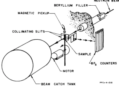
D u r i ng the period that the phased rotor velocity selector installation was under construction, Brugger et al. performed some experiments using a spinning sample t e c h n i q u e13 illustrated in Fig. 9. T he experimental arrangement used a 6^-inch beryllium filter at room
TIME-OF-FLIGHT METHODS 49 temperature in H G -6 beam hole. T h is provided a beam having the usual spectrum of cold neutrons which was defined by c a d m i um slits to an area of 3 X y^-inches. Small ^ - i n c h diameter scattering samples were placed on the end of a rod 3 feet long which were spun through the beam at 1250 r p m. T he neutron burst width was about 29 μ$εο and the time between bursts was 2.4 Χ 104 /xsec.
NEUTRON B E A M
FIG. 9. A schematic illustration of the spinning sample technique. As the sample passes through the beam a pulse of scattered neutrons is produced.
The energy of the scattered neutrons is measured by time-of-flight techniques.
T he neutrons traveled from the scattering sample to a set of detectors located 2 meters from the beam at 90° to it. T he data were recorded on the fast chopper 1000-channel time analyzer wit h 8-/xsec channel widths. W h en this analyzer was not available an oscilloscope wit h a gray wedge and a photographic attachment was used as a time analyzer.
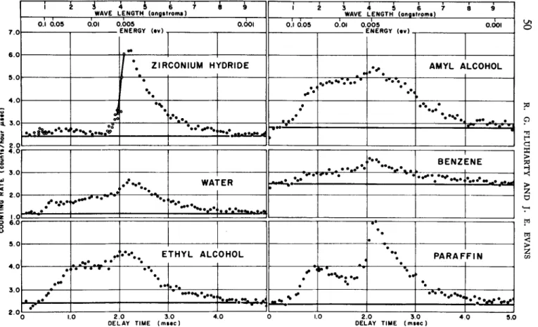
Figure 10 shows the scattering data for water, ethyl alcohol, amylalcohol, benzene, paraffin, and powdered zirconium hydride obtained wit h the above operating conditions. I t is seen that the true counts to background ratio is about 1:1 at the inelastic scattering peaks which occur at 2.1 /xsec. Background was about 2 counts/hour/
/xsec channel width. Since the various samples (except benzene)
* 3
ν 2
~ 3.1
* 2.1 Ο ζ ζ
Ι à i 4 5 6 7 8 9
WAVE LENGTH (angstrom*)
ι
ι ι ι τ - τ 1 1 \1 2 3 4 5 6 7 Θ 9
WAVE LENGTH (angstroms) 0.1 0.05 0.01 0.005 0.001
FMFBftY lmu\
I I ! 1 * • • - T ~
0.1 0.05 0.01 0.005 0.001 F N F B f tY lm»\
ο-
C 0 N I U M Η t O R I D E A M Y L Α L C O H O L
' '··.
• < · , · · » * · · · · - β · ê · •··< ι
J
οο 1*·• •
•
··· · ··· ·
*-—···. - V
····,-·.··-»· -d
•
ψ··.···· ,···. ····.·
Θ Ε Ν Ζ E N E·'"···.,
WA" " E R · · — . · - > . Η .*···*··-·
·'"···.,
WA" " E R*···.··< τ ·*•*—iff »a
·· •
•
··
• T H Y L A L C 0 H 0 L • •··
••
P A R A F F I N
•
···
•ι · · * Τ · •
•
··
• •·· ·· ··
»• •
• ··
2 . 0
1.0 2.0 3.0
OELAY TIME (msec) 2.0 3.0
DELAY TIME (msec) 4.0 5.0
FIG. 10. T h e time~of-flight spectrum of scattered neutrons for various materials as observed by the spinning sample technique. T h e instrumental spectrum function is well represented by elastic scattering for zirconium hydride beyond 2.1 ^sec.
50 R. G. FLUHARTY AND J. E. EVANS
l 1 ι ι 1 ι re 1 ι 1—ν—ι 1 ι 1 1 1—• ι iQ
TIME-OF-FLIGHT METHODS 51 had about the same n u m b er of hydrogen atoms per cubic centimeter, data shown should be directly comparable. T he a m o u nt of multiple scattering is about the same for each sample, which was fairly large, since the transmissions of the samples were approximately 5 0 %.
Since the predominant scattering effect of zirconium hydride is elastic scattering, its distribution beyond 2.1 ^sec is a good represen- tation of the initial flux. For all samples inelastic scattering effects were observed. T he zirconium hydride data shows a peak due to the 0.13-ev optical excitation. Also, the peak due to the hindered rotation in the water data is evident.
T he primary advantage of the spinning sample method was the simplicity of the e q u i p m e n t. Because of the large radius in which the sample moves, e q u i p m e nt built wit h the m i n i m um design in chopper e q u i p m e nt can be made to give relatively good resolutions.
Such technique could be easily adapted to a linear accelerator by phasing the spinning sample wit h the accelerator burst. By changing this phase the input energy of neutrons into the sample could be easily varied.
M o r e recently a cold neutron facility wit h a slow neutron chopper has been installed at the H G -5 beam hole in the M T R .14 Only the pertinent parameters wil l be mentioned, since this is a familiar type of facility. T he beam is filtered t h r o u gh liquid-nitrogen-cooled beryllium 32 inches long by 5 inches in diameter. I t is chopped before reaching the sample to realize the advantages of (1) m a x i m um transmission of the 0.005-ev neutrons, (2) chopper shaping of the beryllium filtered neutron flux to limi t the energy spread, and (3) o b- taining the large solid angle at the counters without limitation by the collimination of the chopper. T he chopper spins at 4500 r p m, has a 2-inch chopping radius, 0.032-inch curved slits, and passes a beam 4 inches high by 1.33 inches wide. T he flight path from the samples to detectors is about 1.75 feet, and the distance between the center of the chopper and the sample is 24.65 cm. T he detector is a bank of 10 B F3 counters 18 inches long and 1 inch in diameter fille d wit h a pressure of 120 cm of Hg.
T he chopper just described is typical of those used on the M T R phased chopper velocity selector. T h e se basic devices, once developed wit h the accompanying motor drives and technology, provide a versatile experimental component for a large variety of experiments.
T o illustrate, a need existed to study the Bragg spectrum being dif- fracted from a beryllium crystal on the crystal spectrometer. T h is
52 R. G. FLUHARTY AND J. E. EVANS
interest results from spectra shown i n Fig. 11, t he counting rate as a function of angle shown for typical operation of a beryllium crystal on t he crystal spectrometer. T h e re are very large fluctuations i n t he intensity which are associated wit h t he variations of t he neutron beam coming from t he crystal. T h e se cannot be accounted for by variations i n t he source neutrons or by abnormal operation of t he spectrometer a rm a nd detectors, and are fluctuations i n t he intensity of t he beam being reflected from t he crystal itself. Such an effect is well known i n t he X-ray field a nd has been described by Rennin- g e r .15 T he principal cause is competition from other planes for t he Bragg neutrons..
ωΙ 0 0
=g 80
5 6 0
& 4 0 jz 2 0 ω 0
< 8 0 LU 60
< 4 0
I
0 20I
808 6 0 ζ 4 0
£ 20
I I I I I I I I I J I I I I I I I I I J I I ι ι ι ι ι ι ι I ι Μ ι ι ι ι ι ι I Μ ι ι ι ι ι ι ι I ι ι ι ι ι ι ι ι ι I ι ι
~_ Be (I0Ï3)
(10131
(0002) J ^ v 'v V ..L'Vt';c 0.10 ev 1
• ^ "' r 0 1 5 e v . • (IQIO) 0.06, ev.
Be (10 7. (1013) _ . - ν *l τ „ (|/0T0). 1 Λ H ) I ftsf* ·. *: f f W ) 0 I 3 ) (ICTI )
A (oooU ?i S r \
\m
/ - (1010) (1231) W • • JX
<O.I5ev. ° ?5v ( , 0 2 ,e > V
r<0002) (Ι0Ϊ3)
( 0 0 0 4 ) —I ι—<Π2Ι) Η
uf0.025ev. ^
Be (1010) ^f,^
(1013)
20
(Ι<5Γ5)(ΙΟΤ3) i
O.lpOey. 0.050ev. (0004)0.025 ev. , , , ^
~0.200ev.
'ΓΓΤÚΊ I I 1*1 Ι Ι Ι Ι Ι I 1*1 Ι i j j Ι I 1 ί I I* M J ι ι ι ι ι ι ι i j j ι ι π ι 1 I I J J I I I I I I I M J I I J_
30 40 50
2 0 DEGREES
60 70 75
FIG. 11. T h e diffraction spectrum observed as a function of angle from various planes of Be with the M T R crystal spectrometer.
I n order to study t he spectral content as a function of arm position Spencer et al.16 set up a chopper i n t he diffracted beam to study the neutron energies by time-of-flight. T w o questions were of particular interest. First, was t he second order, or higher order fractional content of t he beam constant i n spite of t he fluctuations ? A n d second, h ow m u ch of t he fluctuations were d ue to inelastically scattered neutrons a nd would therefore be at undesired a nd varied energies ?
I n Fig. 12, a comparison is made of t he second-order content vs.
TIME-OF-FLIGHT METHODS 53 first-order content of the beam in going over one of the very sharp step functions in the intensity. I t is seen that indeed t he ratio of second order to first order is not a constant over one of these fluctua- tions. O ne would conclude, therefore, that precise measurements
0 ) c c σ
JO.
Ο
C L
c 3 Ο Ο
300 200 100 0 800 700 600 500 400 300 200 100 0
Arm Angle 61° 41'
50 100 150
Arm Angle 6 2 ° 30 2 A
2 0 0
5 0 100 150 Chonnels of Delay
2 0 0
FIG. 1 2 . Comparative time-of-flight spectra of the diffracted neutron beam on both sides of a prominent discontinuity in the total diffraction spectrum near 0 . 0 2 5 ev for the 1 0 1 planes of Be ( 4 ^sec/channel). It is to be noted that the first- to second-order ratio varies rapidly.
using the crystal spectrometer should provide corrections for t he second- and higher order effects for each energy point. Essentially no neutrons in the beam were inelastically scattered neutrons. A small n u m b er of inelastic scattered neutrons were observed at one angle,
54 R. G. FLUHARTY AND J. E. EVANS
but one can conclude that the n u m b er of inelastic scattered neutrons i n such a beam is certainly less than 0.1 %.
Figure 13 shows a schematic cutaway of the M T R phased-chopper velocity selector17 developed under the direction of Brugger. T he first and last rotors are basic since the two rotors i n the middle are simply phased rotating collimators to reduce backgrounds between bursts. T he first rotor gives a chopped burst of neutrons containing a wide energy spread. Since the neutrons travel at different velocities, they arrive at the second rotor at different times. D e p e n d i ng u p on the phase of the second rotor, those i n a very small energy group are transmitted giving a velocity burst of neutrons which continues on to the sample. After scattering from the sample, a time-of-flight measurement is made on the neutrons going from the sample to the detectors. Therefore, by varying the phase of the rotors, the input energy to the sample can be varied allowing the measurement of the inelastic scattering as a function of the angle from the scattering sample σ(Ε, Ε'θ).
T h e re are 15 sets of detectors placed at different angles. T he pulses from the 15 detector angles feed in parallel to the 4000-channel analyzer which is broken up into parallel 256 time channels per detector set. Recently, an additional 4000 channels have been added to allow the sample blank and the sample to be cycled in and out of the beam providing separate analyzer storage capacity for the open.
Figure 14 shows a schematic of the velocity selector intensity vs.
time-of-flight. T he envelope describes the spectrum transmitted by the first rotor and therefore represents the maxwellian spectrum modified by the transmission characteristics of the first rotor.
T he cuts made by the second rotor in his spectrum are represented by the small resolution functions as a function of time-of-flight that are shown underneath this envelope. Figure 15 is a schematic view of a rotor of the choppers typically used in this installation and for the previous applications. I t is seen that a major feature of the design is to use a Soller type slit system allowing a large transmission area through the rotor.
Typical direct output data showing inelastic scattering from methane taken by Randolph et al.18 are shown i n Fig. 16. Even though the background upon which the data is superimposed is fairly large, it has been found possible to analyze the cross sections satisfactorily. Typical cross section values are shown in Fig. 17 as a function of input energy and angle. I n Fig. 18 the complete set has
FIG. 13. A cut-away isomeric drawing of the M T R phased-chopper velocity selector. T h e velocity selecting and chopping actions are performed by the first and last rotors and the two central rotors are rotating collimators.
TIME-OF-FLIGHT METHODS 55
56 R. G. FLUHARTY AND J. E. EVANS
been reduced to the scattering l a w19 form in which one of the variables can be eliminated if one is willin g to assume that t he principle of detailed balance is effective withi n the sample. I t would appear that the Krieger-Nelkin theory provides a fair fi t except for small angle scattering. A more precise averaging over t he Eulerian angles gives a better fi t b ut still fails at small angles. I t n ow appears that t he classical treatment of t he rotational states is inadequate for small energy transfer.
0.15 0J 0.07 0.04 0.025 0.015 0.01 NEUTRON ENERGY
TIME OF FLIGHT FROM SAMPLE TO DETECTOR Τ (/xsec)
FIG. 1 4 . A schematic diagram of the velocity selector intensity vs.
time-of-flight. T h e over-all envelope shows the spectrum transmitted to the second rotor which transmits the narrow spectra underneath for various phase differences between rotors.
Advantages i n using scattering law presentation as proposed by Egelstaff are t he following:
(a) T he data are p ut into a more compact form so that economies can be made i n presentation.
(b) I t allows a systematic method for extrapolation a nd interpola- tion into regions where t he data have not been r un previously.
(c) I t provides t he experimentalist wit h a powerful method for determining whether t he experimental data has systematic errors
TIME-OF-FLIGHT METHODS 57 withi n it. T he data presented in t he scattering law mixing various energies a nd angles wil l not provide a smooth curve unless t he experimental parameters are correct.
-WATER COOLING TOWER
FIG. 1 5 . A typical M T R rotor used for low neutron energy choppers and chopper-velocity selectors. T o optimize the transmission at particular energies the slit curvatures are varied.
58 R. G. FLUHARTY AND J. E. EVANS
33.0001
0 3 0 0 0
1500
- 5 0 0
< 2 0 0 0 oc
1500 g 1000
5 0 0
0
1500
1000
5 0 0
CL
I 1 L /ION BE AM
TO F Γ - ι
•
o
0 16 β3 " r'
;
X
•
2E
• o
<$> ·
°
1
***** as*»**oo 34 ίβ3 7 r'
0
\ if
go1500
1000
5 0 0
0
1500
1000
5 0 0
0
1500
1000
5 0 0
0
1500
1000
5 0 0
0
1500
1000
5 0 0 0]
h*
o - SAMPLE
· - BACKGROUND]
0.07 ev METHANE
—H 1 r
4 3e 2 9 '
5 7 ° 2 5 '
6 5β0 9 '
7 4 ° l l
8 3 ° 12*
2 4 6 8 1000 2 4 " 2 4 6 8 1000 2 4 TIME OF FLIGHT (ttsec)
FIG. 1 6 . Time-of-flight spectra of neutrons scattered from methane for various angles for 0 . 0 7 - e v input neutrons.
TIME-OF-FLIGHT METHODS 59
w Ο
z ο
10* — r
\ 1
! BEAM MONITOR
0.07 . METH
ev ΙΑΝΕ
1
1 1.
•
· · 1 6β3 7 ' -
1
•
•
•
6β3 7 ' -
•
•
) *
v.*
2 !5°44'
* ·
•
f
•
·**
é ****** fj**f~A
^
4° 37'
•
• ·
• •
•
··*
fa»
100
50
Ο
100
Ο
100
ο too
100
Α
ίβ2 9 '
V •Α
>
\
57 β2 5 '
• ·
"Χ
β0 9 '
74 ° ι Γ
83 ο| 2-
1.0 1.5 2.0 1.0 1.5 2.0 WAVE LENGTH OF SCATTERED NEUTRONS ( a n g s t r o m s )
FIG. 1 7 . Typical cross sections as a function of scattered neutron energy for various angles and input energies.
60 R. G. FLUHARTY AND J. E. EVANS
A n example of this was provided by early treatment of the methane data. I t was found that t he scattering events resulting in an increase i n energy a nd those which resulted in a decrease i n neutron energy occupied different curves on t he scattering law presentation until
ιο-'
oa.
α CO
10··
ΙΟ"1
—Q 1 1 1 1 1 11 1 1 1 1 1 I I I
β 8
I 1 1 1 1
« 0
M E T H A N E
SOLID POINTS - ENERGY GAIN OPEN POINTS - ENERGY LOSS
/
~~-^^^J° M
ο Ε,- * 0.0251 ev ο Ej » 0.0706 ev Δ Ej * 0.1002 ev
Τ - 2 9 4βΚ O f0» 8 l b o r n s M » 3.22 Neutron Masses
ο Ε,- * 0.0251 ev ο Ej » 0.0706 ev Δ Ej * 0.1002 ev
Τ - 2 9 4βΚ O f0» 8 l b o r n s M » 3.22 Neutron Masses
- I I I I I I 1 ι ι ι ι ι 11 1 1 I I I -
β • ' / 4 Ρ •3/ 4
Ξ ο ·
X ^ °*
> e ·
/
·* \ --
β • ' / 2 β • 1
o
"T
Ξ
\
* f A — ^ e•A \ ζ - —- 1 I I 1 111 , 1 1 1 1 1 111 I I I I 1 1 1 1 / i l 1 1 1 1 1 I I I 1 1 I Γ
ιο-« ι ιο-' I
a
FIG. 1 8 . T h e complete set of inelastic scattering data for methane pre- sented in the EgelstafT scattering law presentation. Theoretical predictions are also shown. These are reasonably acceptable except at small angles and small energy transfer where quantization of the rotational states must be considered.
TIME-OF-FLIGHT METHODS 61 an error in the energy determination resulting from an error in the flight path was removed.
Brugger is i n t he process of preparing a compilation of the in- elastic scattering data so far obtained which has been presented in the scattering law form. T h is involves data taken in the M T R and data taken by Egelstaff et al. at the Chalk River velocity installation.
I t is expected that this compilation along wit h some discussion of the scattering law presentation wil l be available some time in the s u m m er or fall.
I n the measurement program in the M T R phased chopper velocity selector, methane has been the principal material for testing the instrument and for determining the methods for making valid measurements. T he material was chosen for these initial measure- ments because of its molecular simplicity and because theoretical predictions of the inelastic scattering were available. T h e se studies are now completed and t he data essentially ready for publication.
T he instrument is presently being used to complete studies by S c h m u nk on the inelastic scattering from beryllium crystals, and in the very near future it is anticipated that the instrument wil l be used to measure the inelastic scattering from Na and N a K. Design is u n d er way for a high temperature sample holder, to be used initiall y to study the inelastic scattering from either beryllium or graphite depending u p on their relative priority for reactor purposes.
Measurements have been completed recently on the inelastic scat- tering from Santo wax and from various terphenyls. T h e se are of interest to the organic moderator reactor field. I t is to be noted that the inelastic scattering from these waxes or organics in the solid phase is considerably different from the liqui d phase.
Another concept in time-of-flight applications of particular in- terest to accelerators involves the development of the phased rotors discussed above. T he techniques have now been developed to the stage where phasing is stable to the order of 1 /xsec or less. W i t h this stability of the phased rotor, the possibility exists of using t h em wit h a linear acceleration. By phasing a rotor wit h the electron burst and placing it down the flight path from the linear accelerator, it becomes possible to do activation cross sections. T h is is quite analogous to the procedure of Cowan et al.20 wit h the nuclear explosions. T he material to be activated would be plated on the exterior of t he rotor and the energy dependent activation would depend u p on its position upon the rotor.
62 R. G. FLUHARTY AND J. E. EVANS
I n conclusion, it s h o u ld be pointed out t h at t he reactor source of n e u t r o ns is still very useful in providing small sample cross sections. I n particular, t he total cross sections of radioactive materials a nd of fission p r o d u c ts wil l continue to be of interest for some t i m e.
Reactor source velocity-selector c h o p p er applications wil l c o n t i n ue to be of great interest to reactors i n providing inelastic cross sections.
Also, t he reactor, as a source of n e u t r o n s, is c o m p l e m e n t a ry to t he linear accelerator. M a ny of t he t e c h n i q u es which are p l a n n ed to be used for t he linear accelerator have been developed using reactor sources.
REFERENCES
1. F. G. P. Seidl, U . S. Atomic Energy Commission Rept. B N L 278; F.G. P.
Seidl et al.y Phys. Rev. 95, 476 (1954).
2. J. R. Huffman, Nucleonics 12, 20 (1954).
3. R. B. Regier, W. H. Burgus, and R. L. Tromp, Phys. Rev. 113,1589(1959).
4. R. G. Fluharty, J. R. Smith, and S. D . Reeder, U . S. Atomic Energy Commission Rept. I DO-16633 (1960).
5. M. S. Moore, L. G. Miller, and O. D . Simpson, Phys. Rev. 118, 714(1960).
6. B. G. Nelson, U . S. Atomic Energy Commission Rept. IDO-16510 (1959).
7. O. D . Simpson and M. S. Moore, Phys. Rev. 123, 559 (1961).
8. F. B. Simpson and R. P. Schuman, E A N D C Symposium on Time-of- Flight Methods, Saclay (1961).
9. J. E. Evans, U . S. Atomic Energy Commission Rept. IDO-16163 (1954).
10. R. P. Schuman, J. R. Berreth, and R. G. Fluharty, submitted for publica- tion.
11. J. G. Cuninghame, L. E. Glendenin, and A. L. Harkness, Third Nuclear and Radiochemistry Symposium, Chalk River (1960).
12. C. H. Hogg, L. D . Weber, and E. C. Yates, for presentation at A N S Meeting, Chicago (1961).
13. R. M. Brugger, L. W. McClellan, G. B. Stoutman, and J. E. Evans, Nuclear Sci. and Eng. 5, 99 (1959).
14. R. M. Brugger and J. E. Evans, Paper IS-31, IAEA Symposium on Inelastic Scattering of Neutrons in Solids and Liquids, Vienna, 1960 (1961).
15. M. Renninger, Z. Physik 106, 141 (1937).
16. R. R. Spencer, J. R. Smith, and R. M. Brugger, PNR-36, IAEA Sym- posium on Reactor Neutron Research, Vienna (1960).
17. R. M. Brugger and J. E. Evans, Nuclear Instr. and Methods 12, 75 (1961).
18. P. D . Randolph, R. M. Brugger, K. A. Strong, and R. E. Schmunk, Phvs. Rev. 124, 000 (1961).
19. P. A. Egelstaff, Rept. AERE-R-3622(1961) ; Paper IS/P17, IAEA Sym- posium on Inelastic Scattering of Neutrons in Solids and Liquids, Vienna, 1960 (1961).
20. G. A. Cowan, A. Turkevich, C. I. Browne, and L A S L Radiochemistry G. P., Phys. Rev. 122, 1286 (1961).
TIME-OF-FLIGHT METHODS 63 Discussion
POOLE: I t has been my understanding that precise phasing requires very low bearing friction as provided by low drag air bearings which are used by Egelstaff. I see you use ball bearings i n your chopper.
FLUHARTY: One of the features of this design is that all components set up were available commercially, and the major drag was due to the bearings. On the other hand, the major limitation on the phasing at the present time is due to instability of the oscillator. We have had very good luck wit h the ball bearings being stable and in getting stable phase control. I cannot tell you why, b ut the facts are, the performance is exceptional.
LANDON: YOU mentioned using A u1 98 as your radioactive sample.
Di d you run a resonance structure on gold ?
FLUHARTY: Yes. I have neglected to tell you what the results of that were. T he results are that there appears to be a negative energy resonance at very near zero energy, which is very large, and so far no other positive resonances have been found for very preliminary runs. So, if this is true, it would indicate that one could produce H g1 98 very free of other isotopes, by irradiating gold covered wit h cadmium. T h is is something which should be tested.
LANDON: Do you have a cross section value on this ? Were you able to tell how m u ch A u1 98 is necessary ?
FLUHARTY: T he difficult y at the m o m e nt in getting a cross section value is that the sample was so hot that we are still waiting for it to decay away so as to determine the A u1 98 content. I can say that the value that we observed agrees reasonably well wit h the present value. T h e re is no conflict there. However, wit h the smooth energy variation the integral values may be m o re accurate, and I suspect that we wil l not be able improve the value because of this problem of activity measurement. We wil l not do as precise a j ob on the determination of the very large a m o u nt of activity as has been done i n the past for less active samples.
SHER: T he plot that Evans has made up there—does this show up the analysis of the high thermal cross sections which are dominated by the low energy resonances ?
FLUHARTY: Yes. I n this particular case ; this seems to be successful i n about 7 5% of the cross sections.