MODERN HORTICULTURE
SPECIAL TECHNICAL KNOWLEDGE IN HORTICULTURE
Edited by: Zoltán Láng
Authors:
Miklós Hegybíró (Chapter 4) Sándor Kurtán (Chapter 2, 10) Zoltán Láng (Chapter 3, 6, 8, 9, 11) Sándor Nagy (Chapter 5, 7, 12) András Wieser (Chapter 1)
1. Modern tractors in horticulture
1.1 Basic terms
The basic machines used in plant cultivation, one of the agricultural sectors, are the agricultural power machines, or tractors, as they are called in every day language. These tractors, depending on their application, are in many different versions available.
Plant cultivation can be further subdivided into three areas:
Plant cultivation on arable land: food, fodder and industrial crops.
Horticulture: fruit, vegetable, and wine growing.
Grassland management.
The law on arable land sets forth different categories of cultivation sectors according to their use, which correspond to the basic forms and methods of utilizing land (Table 1.1).
Table 1.1 Agricultural land and the meaning of crop land Cultivation
sector Arable land
Agricultural land
Crop land Garden
Orchard Grapes Grass Forest
Afforested area Marsh
Fish pond
Land taken out of cultivation
In terms of the machines used in horticultural cultivation, we may distinguish between plantations and gardens.
A plantation is established at a permanent location for the purpose of long-term
cultivation. Whether to establish a plantation is a decision to be made for the long-term.
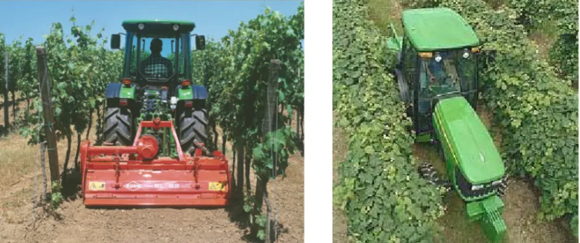
The plantation’s characteristics are that (i) it is planted for many years and (ii) the row and root distance of the plants is determined and fixed for several years. The row distance must be such that it allows the machines to move freely between the rows (Figure 1.1). These are usually arboreal plants (with woody stalk). Consequently, they bear the mechanical effects of the cultivation well.
Figure 1.1 Machines moving between the rows The following is a list of the various plantation types.
Fruit tree: apple, pear, peach, cherry, sour-cherry, plum, etc.
Hedge: grapes, hop.
Bush: berries (raspberry, bramble, etc.).
Intensive: for example, modern orchards.
Tree nursery: growing propagating material.
Planted forest: for example, energy plantation.
Gardens are, for example, the horticultural vegetable cultures.
Their characteristics are:
Cultures (from seed sown or transplanted): herbaceous, low height,
row spacing is fixed.
Row spacing is as big as required for the tractor’s wheels to pass between them (Figure 1.2).
Their height allows the tractor (and its implements) to move above the rows (Figure 1.3).
Figure 1.2 Tractor moving above Figure 1.3 Vegetable cultivation the plants
1.2 Classification of tractors
Tractors may be classified according to many different criteria (Table 1.2). The individual classification criteria interrelate, since, for example, universal tractors, are equipped with different drive systems.
Table 1.2 The main classification criteria of agricultural tractors and their names used Main classification criteria Names used Markings in use
Size / capacity / according to tractive force
heavy semi-heavy light Running component
tire caterpillar rubber belt Power transmission
mechanic
hydraulic (hydrostatic)
mixed (power-split) power-split
Driving system
front axle drive FWD / 2WD
front axle auxiliary drive FWA / MFD
rear axle drive RWD / 2WD
all-wheel drive 4WD / AWD /
4x4 caterpillar / rubber belt
Gear shift
sliding gear synchromesh
under load, adjustable partially or in the full range
semi-power shift full-power shift CVT
IVT Hydrostatic, continuous or
infinitely variable transmission
Steering system front-wheel 2WS
all-wheel 4WS / AWS
joint / articulated
turning brake steering
skid steering skid-steer
Application
tilling tractor universal tractor
special tractors
horticultural tractor tool carrier
plantation tractor gantry
lawn mower (tractor) forestry tractor
communal tractor
1.3. Horticultural tractors
Compared to the universal tractors, horticultural tractors have special structural requirements in order to be suitable for the various utilization areas. The structural requirements are different in each cultivation sector. The following are the most important requirements where recently significant innovations and developments have occurred:
Narrow structural design suitable for moving between the rows.
Adjustable wheel track and clearance enabling movement above the rows.
Several gears and continuous or infinitely variable transmission.
Easy turning: small turning radius to enable the tractor to turn at the end of the rows and, in case of lawn mowers, to avoid obstacles.
Increased stability, for example, on sloping areas.
Universality: front/back attachment possibilities (3-point hitch, PTO, hydraulic attachment).
Universality: possibility for applying a wide variety of adapters.
The following are some modern solutions meeting the above requirements:
Steering: - SuperSteer (New Holland)
- Zero Turn
- Synchro Steer (Cub Cadet) Stability: - Kombi Trak/Terra Trac (Aebi) Communal tractors: - KommunalTrak (KT), MFH (Aebi)
Universality: - Tecno (Avant)
1.4 Plantation tractors
The so-called “plantation tractors” (basically in the universal tractors’ order of
magnitude) move between the rows planted in fixed locations for many years. Therefore, narrow body design and narrow wheel track are the basic requirements (Figure 1.4).
Figure 1.4 Application of plantation tractors The task of the plantation tractors is to operate machines for:
Planting the plantation (for example, building the trellis, pit drilling, post driving).
Cultivation work (for example, shallow tilling, disk harrowing, rotary tilling, chopping of trimmings and their incorporation in the soil, etc.
Treatment of the plantation plants (for example, hedge trimming, crown formation, energy supplying for mechanical pruning).
Plant protection (plant treatment, irrigation, spraying of hedges and limbs.
Harvesting,
o Facilitation of fruit picking, for example, operation of tree shakers.
o Towing of manual picking implements.
o Transportation of material during fruit picking, such as depositing empty crates, transporting pickers, produce, and full containers, in each case to the required location.
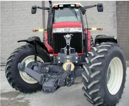
The characteristics of the plantation tractor (Figures 1.5 and 1.6) are the following:
The tractor’s size must be appropriate for the row distance and the height of the plant,
- Narrow wheel track: external width ≈ 60cm smaller than the row distance.
- Gantry: arches over several rows, moves over the plants.
- Universal tractor: adjustable wheel track for work in horticultural cultures on arable land.
Low center of gravity: on slopes, there is danger of rolling over (for example, in vineyards).
Increased clearance.
Significant climbing capability on slopes.
Small turning radius (necessary because of the turn is limited by the row distance).
Low ground pressure and small slip, as the tractor must move on the same track for many years, every year.
Good visibility: the operator must be able to see the cultivating equipment, taking into account especially narrow row distance and dense foliage.
Gentle gear shifting in the cultivation speed range (2-8km/h).
Climbing gear (for planting: ≈ 500 m/h).
Front and rear hitch system/hydraulic attachment to the driving mechanism of the tools and equipments: possibility to attach many different adapters.
Front and rear PTO (with a speed proportionate to the motor’s speed).
Comfort conditions and safe work environment (slopes, branches, spraying) for the operator of the tractor.
Figure 1.5 Plantation tractor Figure 1.6 Narrow gage track
Adjustable wheel track and big clearance are required for tractors cultivating arable land vegetables.
Steering modern horticultural tractors SuperSteer
Already in 1992 New Holland patented a new steering system, SuperSteer (Figure 1.7).
This steering system allows for a radical decrease in the turning radius (according to manufacturing descriptions, even a 30% decrease) and a shorter turning time (Figure 1.8).
At the present, the maximum wheel turning angle is ≈ 55o, since at bigger angles the steered wheels would hit the body of the tractor. With automatic all-wheel drive and a
maximum of 75° steering angle, the Supersteer front bridges make even a 3.4m turning radius possible.
Figure 1.7 New Holland T4050 tractor
Figure 1.8 Turning circle of SuperSteer steering
The SuperSteer steering system combines bogie and axle stub steering in order to achieve the smallest possible turning circle radius (Figures 1.9 and 1.10).
Figure 1.9 Turning circle of SuperSteer
Figure 1.10 Two elements of the steering angle achieved by SuperSteer steering
Figure 1.11 The principle of SuperSteer steering As Figure 1.11 indicates, the steering angle is the sum of the axle stub steering angle (≈
50…55°) and the bogie style front axle swivel angle (max. ≈ 20°). The novelty of this solution is that the front bridge is located in front of the rotational centre of the “bogie”.
This leads to the result that when the “bogie” turns away, the internal, steered wheel moves away from the body of the tractor (decreasing the risk of getting hit), while the external wheel turns in front of the tractor (Figure 1.11).
Figure 1.12 NH T4000 turns in the orchard
The advantage of these structural solutions is that the front additional weight is placed directly on the front bridge. Therefore, in case of an all-wheel drive the pulling force is almost constant also during steering. These structural designs have a disadvantage as well. The front 3-point hitch (as it is attached to the front bridge) does not turn away completely; it only follows the turning of the bogie. In addition, the front transmission shaft does not turn at all, which in case of such a significant steering angle may cause the front transmission shaft to hit the other structural parts (Figure 1.13).
Figure 1.13 The front 3-point hitch and front transmission shaft of SuperSteer
1.5. Lawn tractors
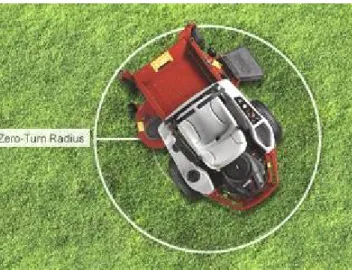
Figure 1.14 Zero-turn lawn mower
Figure 1.15 Frontal self-adjusting wheels
Dumb-waiters, shopping carts, strollers, etc. (but also, for example, armchair rollers) are well-known for the fact that their front wheels always set themselves to the travel
direction no matter in which direction they are pushed. This concept is utilized in steering the so-called “zero-turn” lawn tractors which turn in their own length. An important requirement for these tractors is that they should be capable of appropriately approaching and avoiding obstacles (for example, tree trunks, shrubs, bushes, etc.) in order not to leave uncut or untrimmed area.
Their structural design has two main features.
1. The front wheels are not driven. They can make a full 360° turn around the vertical axis. However, it is an important principle that while the axis of the wheels is
perpendicular to the vertical rotational axis, in relation to that it is in a deviating position (Figure 1.15).
2. The rear wheels do not turn (they have a fixed axle) and are driven hydrostatically, independently from each other. It can be observed on Figure 1.14 that the tractor’s operator can adjust with the continuous or infinitely variable transmission and the two joysticks the revolution and even the turning direction of the two rear wheels
independently from each other. In case of traditional front-wheel axle stub steering the center of the turning circle is outside of the vehicle on the extension of the axle line of the rear driven wheels. In this case however as the center of the turning circle is the center of the rear fixed axle, with directing the drive, the tractor can even turn in its own length (Figure 1.16). In this latter case, the two rear driven wheels revolve with the same speed, but in contrary direction.
Figure 1.16 The turning circle radius of the tractor turning around its axle One practical disadvantage of this solution is that in case of sharp turns the front wheels may dig up the soil and damaging the grass specially, sensitive grass. The other
disadvantage is the lesser stability on slopes.
Cub Cadet Synchro-Steer
Figure 1.17 Synchro-Steer lawn mowing tractors
The Synchro-Steer steering mechanism patented by Cub Cadet in 2009 is actually the development of tractors turning in their own length mainly for the purpose of solving the above mentioned problems of digging up the soil and grass, and stability (Figure 1.17).
This solution retained the independent drive of the rear wheels, but the steering and the turning of the front wheels are accomplished by the operator turning the steering wheel.
Figure 1.18 The principle of Synchro-Steer
As Figure 1.18 indicates, when the steering wheel is turned, the front wheels turn, simultaneously regulating hydraulically the revolution of the rear driven wheels and, if necessary, their turning direction. Two foot pedals set the travel speed. This design enables the tractor to turn in its own length (Figure 1.19) and, on slopes, allows for a significant increase in stability at the time of turning.
Figure 1.19 Synchro-Steer turning around its axle Stability of lawn mowing tractors
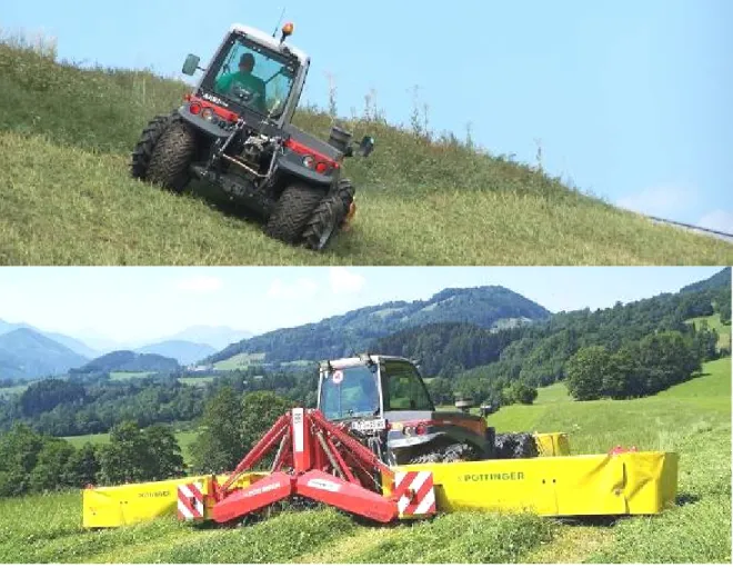
Lawn tractors must often work on sloping areas such as on hills, on the banks of ditches, on the side of banks or dikes. In these cases, the primary criterion is the stability of the tractor.
In the 1950s an Austrian company, Rasant, developed a special tractor which is suitable primarily for working on alpine pastures (Figure 1.20). Later, the Swiss AEBI bought the company. Since 1976, its TT (TerraTrac) tractor group (with a capacity range between
80-130 HP, 60-95 kW) has been world wide one of the most well known power machine in its category (Figures 1.21, 1.22, and 1.23).
Figure 1.20 Rasant KombiTrak
The main design features are the following:
The lowest possible mass center in the interest of increased stability. This is served by the portal-axle style transmission placed between the compensating gear and the wheel, which if compared to the traditional application is used the other way around.
Stability is secured by 1:1 ratio of the axle distance to the wheel track
Infinitely variable transmission (IVT) and hydrostatic all-wheel drive (4x4, 4WD) to ensure flexibility.
All-wheel drive (4WS) to ensure easy turning.
Excellent cross-country capability, tires with special moulding, on occasions, double tires.
In the interest of operator comfort, operator cab designed with shock absorber, convertible roof, and roll over protection system (ROPS).
The front and back 3-point hitch, the PTO, and the hydraulic plugs help universal application.
Intelligent field-profile tracking automatics for the lawn mowing adapters mounted on the front hitch.
AEBI TerraTrac
Figure 1.21 TerraTrac TT70
Figure 1.22 Front attachments a), b)
a) b)
Figure 1.23 Characteristic dimensions of TerraTrac: a) TT75, b) TT270 The TerraTrac drive system (Figure 1.24) consists of a diesel motor located beside the driver seat, a high-pressure hydraulics pump, and a hydro-motor. The middle
compensating gear distributes power between the front and the rear axles. On each axle there is a compensating gear for separating the half-axles. The portal style transmission between the compensating gear and the wheels ensures the low center of gravity required for preventing the tractor from rolling over, although this, as a result of the low clearance, reduces cross-country capability. A mechanic distributor mounted on the diesel motor drives the front and rear transmission shafts.
Figure 1.24 The drive system of TerraTrac (source: AEBI machine catalogue)
On Figures 1.25 and 1.26 the top category of the prime mover family is shown.
.
Figure 1.25 TerraTrac TT270
Figure 1.26 TT270 in use (equipped with a soil miller)
TerraTrac lawn mowers in use Extreme slopes
Figure 1.28 Applications of TerraTrac lawn mowers
The machines used as examples on Figure 1.28 illustrate this version’s suitability for work on steep slopes.
When using lawn mowing adapters, deteriorating work quality resulting from sudden changes in the field may be prevented by the front hitch intelligent field-profile tracking device (Figure 1.29) which functions with an electronically steered hydraulic pressure adjusting equipment.
Figure 1.29 a) sudden slope, b) sudden climb
Although this version was originally developed for lawn mowing, its current design allows its universal application in difficult field conditions as well. As a result of
different attachment possibilities, the availability of various adapters, and the good cross- country capability, it can be used for mulching, snow clearance, snow milling, but it is also capable of towing or transporting smaller machines.
1.6. Communal tractors
By developing the basic machine, AEBI created the KT (KommunalTrak) family with articulated steering and a rear loading area. Its different versions are primarily used in the cities for cleaning and in parks for lawn mowing and garbage collection (Figure 1.30).
Figure 1.30 AEBI KT-50
As a result of the various possibilities for attaching adapters, the AEBI machine family marked with MFH (MachinenFabrik Hochdorf) is excellent for cleaning and watering city streets and roads, and foliage and snow clearance (Figure 1.31).
Figure 1.31 MFH2500 Street cleaning machine
The TP (TransPorter) transporter-vehicle family utilizes the cross-country feature of the basic machine. It is suitable also for use on steep slopes and has a 6x6 drive, pick-up transporter version (TP97) as well (Figure 1.32).
Figure 1.32 TP transporter
Small-sized horticultural tractors
There is a constantly increasing demand for small-sized machines of universal application with extremely good turning capability and a wide variety of adapters.
The Bobcat category used since the 1960s, is the best representative of this structural design.
AVANT Tecno
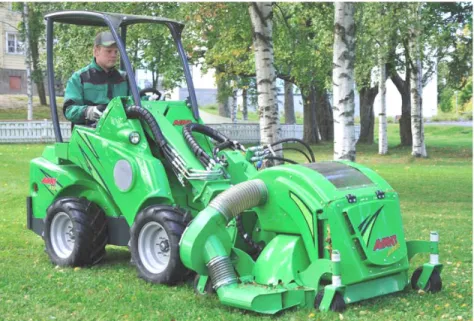
The latest machine family in this category is the machine variety of the Finnish company, AVANT, founded in 1991, which is best known for its front adapter attachment. The multi-faceted Avant small machines are suitable for performing tasks in a variety of narrow spaces (in the construction industry, agriculture, garden and park landscaping, maintenance) whether the task is soil work, loading or even lawn mowing (Figure 1.33).
The characteristics of this machine family are the following:
Constant, all-wheel (4x4) hydrostatic drive with hydro-motors built into the wheels. Steering is done by two pedals. One regulates the speed of forward travel, the other the speed of backward travel, with continuous or infinitely variable transmission. The speed is proportionate to the pressure on the pedal.
Wide variety of motors between 13-50 kW (18-70 HP) (petrol or diesel).
Skid-steering (possibility for the tractor to turn in its own length) or articulated steering to protect soil and grass.
Modern solution for front hydraulic adapter attachment (“boom”). The front lifting may be steered by joystick-style arms.
Level controlling arm: possibility for automatic switching to horizontal position.
Variety of adapters: universal application, multi-functionality (more than 50 types of adapters are available, for example, for soil work, loading, and different adapters driven hydraulically).
Rear towbar: towing possibility.
Low center of gravity ensures great stability.
Operator’s comfort: cab with 360°visibility, protective roof, tubular frame providing protection in case the tractor rolls over (Roll-Over Protection System).
Options: revolving light, etc.
Figure 1.33 Avant Tecno lawn mower with adapter
The Avant machine family is similar to the Bobcat in some respects. One similarity is that some of its versions also use the skid-steer steering system applied by Bobcat in order to achieve a smaller turning circle and to enable the tractor even to turn in its length.
a) b)
Figure 1.34 a), b) The theoretical construction of Skid-Steer
Skid-steer is the typical steering method of small-sized trucks and universal mini-loader machines requiring great flexibility. Skid-steer actually utilizes the principle of
caterpillar steering and all its operational methods (including when the tractor turns in its length) on vehicles running on wheels.
The small diesel motor drives a dual cog-wheel pump which supplies high-pressure oil to a hydro-motor mounted on each side. The speed and the turning direction of the two hydro-motors may be adjusted with continuous or infinitely variable transmission by two joysticks. Each of the hydro-motors turns the wheels on its own side with forced-
connection drive (usually with chain drive) in order to achieve complete synchronization.
By appropriate steering simultaneously on both sides it can be achieved that the wheels on the two sides turn with the same speed but in the opposite direction. As a result of this, the machine’s turning center will be a point to be determined by the half of the axle distance and the half of the wheel track, meaning that the machine turns in its own length.
The disadvantage of this method is that moving on hard (for example, asphalt or
concrete) surface greatly wears out the tires because of their slipping, and moving on soil damages the soil substantially (Figure 1.34).
The real innovative feature is the front adapter attachment. This is located on a middle arm that may be lifted. The hydraulic attachments necessary for driving the active adapters are placed also on the middle arm (Figure 1.35).
Figure1.35 Avant Tecno front hitch a) elevated b) lowered
Articulated steering (Figure 1.36) decreases damage to the soil and the plants. Figure 1.37 shows an example for the operation of the level controlling arm with the possibility for switching automatically to a horizontal position.
Figure 1.36 Articulated steering
Figure 1.37 The automatic leveling of the elevating arm
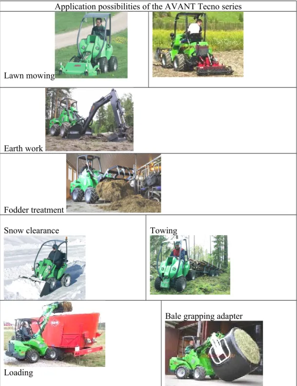
Figure 1.38 shows some characteristic applications of the small-sized machine.
Application possibilities of the AVANT Tecno series
Lawn mowing
Earth work
Fodder treatment
Snow clearance Towing
Loading
Bale grapping adapter
Figure 1.38 Avant Tecno applications
1.7 Application of Quad (ATV) in horticulture
This machine was developed in the 1960s in Japan for the purpose of enabling travel from closed-off mountain villages to towns. Not surprising, therefore, that even today the most well-known manufacturers of these machines are Japanese companies, such as Honda, Yamaha and Kawasaki.
By 1970, the Qaud appeared also in the US, first as a sports vehicle. Since 1980, American farmers have started to use it in field traffic, transportation and, later on, in forestry, horticulture, and grape cultivation as well, even in animal breeding, for example, in cattle driving.
Today, the “quad” vehicle is often used in horticulture because of its small size,
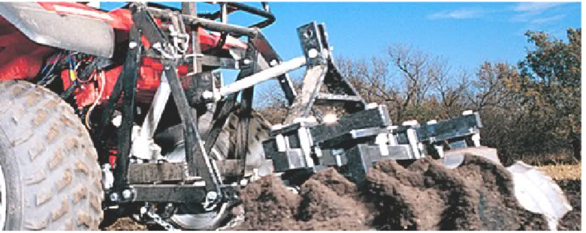
flexibility, good cross-country capability. If used as commercial vehicles they are usually called ATV (All-Terrain-Vehicle). Currently, there are many different adapters and fittings available. For example, towbar, front or rear hitch systems, or even PTO can be ordered (Figues 1.39, 1.40 and 1.41). In the US, the law defines it as a separate category (MAV: Multipurpose Agricultural Vehicle)..
Figure 1.39 3-point hitch on an ATV The main features of ATVs are the following:
All-wheel drive.
Its motor is usually bigger than 400cm3.
Its capacity is greater than 25 kW (35 HP).
Its mass usually exceeds 350kg.
For transporting smaller masses, it usually has a front and rear loading area.
It is supplied with towbar.
Figure 1.40 Yamaha ATV manufactured in 1988, supplied with a transmission shaft (Terrapro PTO)
Figure 1.41 Lawn mowing with an ATV supplied with a transmission shaft The quad as an ATV has become a useful, multi-functional machine on farms.
On Figure 1.42 several agricultural applications can be seen.
Agricultural/horticultural application of the ATV
Transportation
Spraying Lawn mowing
Towing
Field leveling
Figure 1.42 Agricultural applications of the ATV
Control questions:
1/ How can the agricultural tractors be classified?
2/ Which are the main characteristics of a plantation tractor?
3/ How does the SuperSteer steering is working? Sketch its arrangement!
4/ Sketch the construction of the zero-turn lawn tractors!
5/ Why is the stability of the loan tractors important? How can their stability ensured?
6/ Characterise the modern universal small tractors!
7/ How does the skid-steering works?
8/ What does the ATV is meaning? In which area of the agriculture can they be used?
2. Machines used before and during planting. Soil cultivation in the production of vegetables, fruit and grapes.
2.1 Machines used preceding the planting
2.1.1 The meaning of the term „land improvement”, its main tasks and the preparation of the area for cultivation
The planting of horticultural plants (such as grapes, fruit, berry fruits, nurseries) requiring constant soil supply is preceded by careful planning and organization. The arable land must be capable of production, and all producers are obligated to maintain and protect its fertility.
The term „land improvement” means any effect (intervention, procedure, method) or system of effects on the soil, the purpose of which is to:
a) increase soil fertility permanently, and
b) terminate or substantially decrease unfavorable natural conditions.
Land improvement activity means performing all agro-technical, biological, chemical, and technological (soil protection, land drainage, water utilization and other) procedures in order to protect the fertility and the condition of the soil.
The elements of land improvement are the following:
- re-shaping sloping areas,
- soil protection (forest/shelter belts, erosion, protection against deflation), - water management (termination of water rills), drainage, and
- soil improvement (changing the soil’s chemical reaction, for example, by using lime).
The purpose of land improvement is to perform any and all tasks on agricultural land in the interest of production, and to create the optimal conditions required for the
application of production technology, work organization, modern technology, and effective soil protection.
2.1.2 LAND USE PLANNING
Before the geodesic marking of the land designated for planting, it may be necessary to remove trees, shrubbery, bushes, and stones preventing earth work. Two main categories of machinery are used in this phase, machines used in the field clearing and field shaping.
Machines in field clearing
- machines used in clearing shrubbery and bush
bush crushers,
bush breakers, and
bush cutters
- machines used in handling stumps
stump extractors,
fraises,
millers, and
stump cutters (machines cutting around the stump)
- root rakes - stone removers
In exceptional cases, machines for replanting old trees may also become necessary if a valuable plant must be removed in the interest of utilizing it in another location.
Machines in field shaping
dozers,
scrapers, and
graders
The soil is prepared before marking the earth work. In field clearing, the most important machines are those involved in clearing bushes, handling stumps, and removing stones. (Szabó, 1977)
2.1.2.1 Field clearing machines
Machines used in clearing shrubbery and bushes
Bushes can be cleared by crushing, breaking, and cutting. Generally, caterpillar tractors, capable of easy field maneuvering, are used. Bush crushers work most
efficiently. These are manufactured in full or semi towed versions. Crushing and chopping are done by knives rotating with a high revolution per minute (5,000 rpm).
Cutting is assisted by a reciprocating-blade. The equipment is capable of chopping branches with a diameter of even 50-60mm. Bush breakers work successfully on areas covered with dense shrubbery. The machine consists of drum crushers with a diameter in excess of 400mm, equipped with breaking blades. It weighs 1.4 – 10 ton, and is towed by a 30-75 kW tractor.
Brush cutters are mounted on caterpillar tractors with easy field maneuvering capability. Generally, they consist of two main parts: a universal sliding frame and a working unit. (Figure 2.1)
Figure 2.1 Brush cutter
The universal sliding frame is hinged with the engine. A plate with cutting edges, replaceable at the bottom, is mounted slantwise on the sliding frame. These cut the roots.
Hydraulic cylinders adjust the cutting depth. While moving forward, the machine’s cutting mechanism shoves the shrubbery and the bushes horizontally to the sides while, at the same time, reaches under them, cuts and lifts them out. The machine’s work width is 2.8 – 3.6m, and its area capacity is 0.3 – 0.5 ha/h.
Machines used in handling stumps
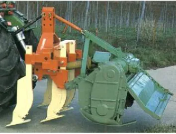
Handling stumps is one of the hardest and greatest energy consuming tasks in field clearing. In the simplest case, a tractor equipped with a cutting edge and a sliding plate may be used. (Figure 2.2)
Figure 2.2 Stump extractor with sliding plate
The task of stump extractors, regardless of the tree type, is to remove big stumps from the soil. Hydraulic versions have replaced earlier used mechanical versions. With these machines, in addition to removing stumps, trees may be felled or the soil may be cleared from bigger stones which may then be transported to a nearby area. The stump is approached by the equipment in reverse. In this position, the machine sinks into the soil.
Afterward, by lifting the post and the equipment simultaneously and tilting the post backwards, it removes the stump from the soil. Depending on its make, the machine is capable of removing 150 – 300 stumps in every 10 hours. The engine operates with 75 kW.
Fraises and millers with a diameter up to 500mm are economical. These may be used also for removing stumps left on the cutting area.
Figure 2.3 Stump extractors
The PTO drives the machine mounted on the tractor’s 3-point linkage hitch system. Its operating element is a short taper screw (Figure 2.4a) which, by penetrating the stump, splits it apart, and the milling disc splinters it. An engine with at least 60 kW is necessary to drive the stump miller (Figure 2.4b) which may be attached with a 3-point linkage hitch. The milling drum is driven via the PTO through the transmission shaft, angle gear, and V-belts.
Figure 2.4 Fraise, miller
The machine’s structural specialty is that the milling drum is equipped with milling knives fixed to the milling drum’s mantle enabling them to rotate free around their horizontal axle. The edge of the replaceable milling knives is made of a heavy metal, blunt-proof facing. The knives are installed along a helical line.
The machine’s drum cutting around the stump (Figure 2.5) is driven mechanically via the tractor’s PTO. The drum is made of a plate mantle, with a rim welded to its top.
The drum attaches to the driving box through this. The drum may be manufactured in different diameters (usually 500 – 700mm) and lengths (usually 800 – 1,200mm). These dimensions determine the machine’s utilization possibilities. A knife-wreath attaches to the lower part of the drum, with internal and external grading teeth.
Figure 2.5 Stump cutter
The spiral shaped belt on the drum removes shavings and earth. A hydraulic cylinder operating the ejecting drum – is attached to the top part of the drum. After the stump has been cut around, the ejecting drum ejects the stump heart after having lifted cutter drum and tilted it backwards. A tractor with 60 – 100 kW is necessary to operate it depending on soil compaction and the diameter of the stump. (Horváth B., 2003)
Root rakes
Root rakes (Figure 2.6) are used for removing the roots left in the soil after handling the stumps. The equipment consists of a rigid, closed-profile frame with rigidly attached teeth.
Figure 2.6 Root rake
As the tractor moves forward, the replaceable steel teeth mounted on the beam pull out and collect the bigger roots left in the soil. The teeth working in the soil are chisel shaped. The process is carried out perpendicularly to each other in a 20-40cm depth which helps further work. This machine’s structure is similar to that of the ruter or ripper discussed later. The difference is that in this case they use a greater number of, thus more densely set, ripping knives.
Stone removers
There are two types of stone removers. One type is leaving the stons behind in swath, (Figure 2.7) and the other type with collects them in a container (Figure 2.8).
Collecting the stones may be carried out in two phases or in one phase. In the two-phase procedure, in the first phase, the stones are rolled into swath, in the second phase, they are picked up into a trailer equipped with a reel.
Figure 2.7 Ordering stone remover
Figure 2.8 Stone remover with a container
When work is performed in one phase, the stone remover puts the collected stones immediately into the container. (Figure 2.9)
Figure 2.9 One-phase stone remover
The collected stones can be used for marking property borders, building fences or farm roads.
2.1.2.2 Machines used in landscaping and landshaping
On the field cleared from trees and bushes, the soil is prepared for planting by using equipment designed for landscaping and landshaping. These are machines used for excavating, leveling or incorporation of soil or material similar to soil. From the
landscaping machines, primarily earth excavators and transporters are used. There are two groups:
- machines with a boot or bowl, and - machines with cutting edge (plate).
Machines with a boot or bowl collect the scraped-off soil in a container similar to a crate and deliver it to the location of incorporation. One such machine is the scraper.
Machines with a cutting edge roll the scraped-off soil in front of the cutting edge and push it nearby or further away (dozer) or spread it (grader).
These machines must be mobile and have a good maneuvering and turning capability.
Their repair and transportation must be quick. In addition, the number of their servicing personnel must be low, and they must be cost efficient and suitable for many purposes.
Another important criterion is that they should easily fit into the machine chain.
The theory of soil scraping
The scraper must be moved with specific strength to make sure that the soil scrapings can fill up the bowl following the edge. As it can be seen on Figure 2.10, the scraper’s blade edge’s angle is . The plate of the scraper’s edge is at directional angle to the normal of the soil surface. As a result of the cutting force, the soil compacts, and the scraper plate presses the soil particles in direction FN. When the pressure reaches a certain value, the soil layer splits off at angle depending on the soil condition,
composition, shape and setting of the scraper. In order to achieve the smallest scraping force, the force required for scraping at different and angles must be determined.
Furthermore, one has to determine the optimal value of angle , resulting in the smallest scraping force. The value of the internal frictional angle among the soil particles changes between = 0°- 45°.
Figure 2.10 Angles characteristic of scraping
During scraping, , the break-off angle of the soil, depends on the quality and condition of the soil, and the shape of the scraper. As Figure 2.10 indicates, when scraping compacted, semi-saturated soil, the shape of the soil parts splitting off in a bending manner below angle is almost like a trapezium. If the soil is very dry and compacted, regular soil scraping cannot be formed. In this case, soil scrapings break off in irregular pieces and, as shown on Figure 2.11, angle may have a negative value. If the soil is soft, because its water content is greater than optimal, scraping may not be characterized with angle , as the soil scrapings break off in continuous ribbons. In case of soil without cohesion, for example, sand, the soil crumbles into grains and collects on the scraper’s blade. Calculations and practical experience prove that the optimal angle of digging-scraping is independent of the frictional angle and its value = 20° - 22°
hardly changes.
Figure 2.11 Splitting dry, compact soil
Therefore, the plate of the scraper’s blade must be set at angle 20°- 22° to the soil.
The frictional angle has great influence on the scraping force. For example, in case of muddy soil, if the water content decreases from the optimal 20% to 15%, the
specific scraping requirement will be almost 7 times greater than in case of soil with normal water content.
If the edge of the blade has a small cutting angle (about = 10°), it blunts very quickly, greatly influencing the size of the scraping force. If the edge of the blade is of 2mm radius originally and, as a result of wearing out, blunts to a 16mm radius, the scraping resistance will be 35% greater. If the tool’s cutting angle is increased from 30° to 50°, the scraping resistance will increase by 20%. The splitting angle must be kept between 0° and 90°. If the soil is hard, the value of approaches 0, but it can also be negative. This may be avoided by using breaking teeth attached to the front of the cutting blade’s edge. The teeth will break up the soil and make it grainy.
In structurally loose soil, where is between 40° and 50°, such as sandy and pebbly soil, using breaking teeth is not economical.
Based on the foregoing, the cutting edge’s angles are arrived at as follows. , the rear angle, should be between 5° and 10°, in order to prevent the friction of the blade against the scraped soil, since this would greatly increase the scraping force. The optimal value of cutting angle is between 20° and 35°, in which case, , the directional angle, will be between 50° and 60°. This is advantageous if the soil is hard and dry, and the blade is made of sheering steel. In case of sculptured soil with optimal water content, cutting angle is between 55° and 65°, because this results in the optimal directional angle, that is when is between 20° and 25°.
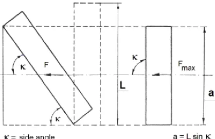
On modern machines, they use self-sharpening blades, the so-called sandwich steel blades. The lower plate is extremely hard (alloyed), but thin, and the upper plate is made of thicker, durable steel. During scraping, the upper plate continuously wears out, but the lower thin, hard steel plate (resistant to wearing out) does not allow the blade to blunt. If the blade’s edge is not perpendicular to the direction of scraping, but tilted (side angle < 90°) (Figure 2.12), then the change in the scraping force is a parabolic function according to the diagram shown on Figure 2.13 and at = 45° the decrease in the specific scraping force is only 10%.
Figure 2.12 Tilted scraping edge
Figure 2.13 Decrease in scraping force as a function of the side angle
The scraped-off soil scraping must slide on the blade’s plate and later inside the scraping bowl on the bowl’s walls shaped and surfaced so as to comply with the laws of flow. The smooth metal surface has much greater resistance than rough or wavy surfaces.
The blade must be free of protruding screws, rivet-heads, or indentations, because behind or in these the soil gets in the flow’s shadow and sticks. In order to determine the shape that complies with the laws of flow, first the flow speed must be determined. The flow speed and the flow’s pressure must conform to the profile’s curve. The more
concave is the profile, the harder is the flowing soil scraping squeezed and forced to flow along the wall, for example, upwards.
The scraping force characterized with a simplified equation:
F = a . b . p (N) a – the thickness of the soil scraping, cm,
b – the width of the soil scraping, as well as the length of the scraper blade, cm, and p – the specific scraping resistance of the soil, N.cm-2.
If the soil work machine cannot provide the required F towing power, because p, the specific scraping resistance, increases, one must decrease the thickness of the soil scraping, but never the speed of the scraping.
The scraping speed should be high rather than low. The scraping’s power requirement does have an optimal speed. On the curve on Figure 2.14, the maximum towing power is achieved when the speed is very slow.
Figure 2.14 Scraping power as a function of speed
Even if the scraping blade is towed at a speed higher than the optimal speed, the towing power will increase by only about 24%. Therefore, it is advisable to increase the excavator’s scraping speed up to the technological limit, if necessary, even by pushing the machine, because, as the scraping slows down, the machine may easily throttle down and stop. (Karai - Horváth 1992)
Scrapers
Among the soil work machines, almost without exception, only the scraper is capable of performing complex work processes. Set forth below is the usual work order of moving soil:
- breaking up and scraping the soil, - lifting the material,
- putting it into the transportation equipment, - delivering it over the required distance,
- spreading it in layers with the appropriate or required thickness, and - compacting the earth moved
The scraper performs these tasks all by itself.
Figure 2.15 shows the different types of machinery.
Figure 2.15 Scrapers
a – one-axle towed scraper, b – two-axle towed scraper, c – saddled, d – self-propelled The two-axle towed scraper is the best known mid-sized type. Most self-propelled scrapers (Figure 2.16) are supplied with rubber tires; caterpillar types are rarer. Its working tool is a bowl equipped with a cutting-edge, supported by one or two axles. The bowl is hinged with the frame. Most often, it is steered mechanically or hydraulically.
The bowl is welded of steel plates, and its sides are stiffened by U steel welded on from the outside. The bowl’s front wall consists of a swinging door, while its rear wall consists of a sliding door. The scraping blades are mounted on the front of the bottom plate. Usually there are three scraping blades, and as they do not blunt at the same rate, not all blades are replaced or sharpened at the same time. Also the breaking teeth are placed here. A short side knife is fixed to the bottom part of each of the two side plates, with which the side plates of the lowered crate can also scrape the soil.
The scraping angle is adjusted depending on the extent of compaction and saturation of the soil. The scraper’s work consists of scraping, transportation, emptying, and returning to the location of the scraping.
Scraping requires two or three times greater towing power than transportation.
During scraping, as the crate is being filled up, the need for towing power can increase to such a degree that the machine throttles down and stops. To help the scraper, a dozer may be attached to it; the scraper’s rear frame is designed to enable such attachment. The two machines together can overcome the problem described. Usually, one dozer is sufficient for 4 – 6 scrapers.
After scraping, transportation must be carried out over the shortest possible distance and at the greatest possible speed. Depending on the transportation distance, machines have different crate volumes. Crates with a volume less than 3m³ are used on a distance between 50 – 300m, crates with a volume of 6m³ on a distance between 100 – 400m, towed crates with a volume of 9 - 10m³ on a distance between 300 – 700m, and crates with a volume exceeding 10m³ are used on a distance between 700 – 2,000m.
Emptying is performed by forced emptying (the sliding plate in the back of the scraping crate pushes out the soil) or semi-forced emptying (the tilting mechanism of the scraping crate throws out the soil), while, in case of smaller machines, it is done by free emptying (the soil is thrown out simply be turning it over). In this phase, the machine dumps the delivered earth into the indentations. In case of free emptying, the mounds of soil left behind must be flattened by other machines, for example, by dozers.
Figure 2.16 Hydraulic self-propelled scraper
In idle runs, the scraper is elevated to transport position. The scraper should return to the scraping location quickly, using the shortest way to decrease the cycle period and to make work more efficient and economical.
The one-axle scraper is also towed by separate power unit. Its advantage is that it is 2 – 2.5m shorter than the previous type. Consequently, even in a tight space, it turns
easier than the long, two-axle towed scrapers. If the power unit is supplied with
pneumatic rubber-tire, it may move with a higher speed than the caterpillar type, namely with 20 – 25km/h. A scraper moving with such speed is economical even if it transports over a distance exceeding 1,000m. During scraping, this type also requires pushing, because the tractor’s engine is not designed to cover the excess work of scraping. This scraper’s technology, filling and emptying functions are the same as those of the previous types, but it is much more mobile. (Horváth B. 2003)
Figure 2.17 illustrates the machine’s moving methods.
Figure 2.17 Moving methods of scrapers
The scraper which moves on a circular (or elliptical) path is used on greater distances. Its disadvantage lies in the many round-trips and idle runs. Therefore, it is better to operate the scraper in a winding manner or following the form of the number eight. In the latter case, the fully loaded scraper does not have to make sharp turns. In addition, in one full round-trip, two scraping and two emptying tasks can be performed and higher speed may be achieved. Therefore, the entire work process is more economical.
Graders
The graders, while moving ahead, scrape and grade the earth. Two main types are known, the towed and the self-propelled, motorized graders. Some towed graders are also equipped with an engine. This makes steering and the adjustment of the grading knife easier, but plays no role in the towing itself. The grader is used mainly for finishing types of earth work, only rarely for moving earth for production. It grades the crown of the bank, the sole of the indentation, the ditch, and the bank of the indentation according to the required profile, most often after the completion of soil compaction. Occasionally, it hoes the earth on a big area, sweeps aside the humus layer, thereby preparing the field for soil work.
The tool of the grader is a big, concave grading knife, and is somewhat similar to the sliding plate of the dozer. The grading knife may be set to all three main directions.
(Figure 2.18)
The grading knife is attached to the frame, the position of which can be adjusted by hydraulic cylinders. A hydro-motor driving a big cog-wheel can adjust the grading knife’s angle to the travel direction. After having turned back the grading knife completely, the breaking teeth may be turned down. With this knife position, frozen earth surface and old, bad roads can be broken up. The frame is a rigid, welded steel structure or a beam bent and welded from square pipes. The grading knife, the steering equipment, and the wheels are mounted to the frame. As the machine operator can see the grading knife from the cab, he can accurately direct work.
The four wheels are supplied either with iron hoops or with pneumatic rubber tires. The wheels are not spring loaded, as the movement of the spring would result in a wavy surface.
Figure 2.18 Motorized grader
The tilt and height of the wheels, the relationship of the frame and the wheels may be changed significantly. Sometimes a wheel on the one side runnes in the ditch, while another wheel on the other side moves on the bank.
A diesel engine unit pushes the motorized grader from behind. It does not necessarily have to be always in the back, because if, for example, there is not enough room for turning around, the grading knife is turned and the grader is towed by the engine being now in the front. Modern graders are, without exception, equipped with engine.
Dozers
The basic unit of the dozer is the great adhesion caterpillar or rubber-tire tractor (Figure 2.19). Most often, the two sliding shanks hinge with the bridle which also hinges with the chain frame or the chassis of the tractor. The dozer plate, with adjustable tilt and slant, is mounted on the end of the sliding shanks.
Figure 2.19 Dozer
Dozers with dozer plates which cannot be turned in the travel direction are called bulldozers, capable of moving only up and down. The dozer plate is a 2.5 – 3m long and 0.8 – 1.2m wide concave steel plate stiffened by a skeleton on its back. The two main flanges, to which the sliding shanks attach are such that, with the supporting bars of the sliding shanks, the concave dozer plate can be adjusted at different scraping angles (cutting angle) in accordance with the soil’s internal friction.
While the dozer is moving, the machine operator lowers the dozer plate into the ground. Then the scraping blade fixed to the bottom edge of the plate scrapes out earth shavings, which pile up on front of the plate. If the dozer plate’s perpendicular segment is shaped so as to satisfy the laws of flow, the earth shavings will flow upward in front of the plate and roll up during movement. The dozer pushes the soil as long as soil work
and transportation require it. The dozer should be operated on short distances, as a portion of the rolled earth will be left behind at the sides of the plate. In order to avoid this result, in case of some dozer plates, the two ends of the plate are closed by welded side plates.
In earlier versions, the dozer plate was placed directly under and in front of the cooler of the engine. In newer versions, the engine and the cooler are mounted on the rear of the machine. As the driver sits closer to the dozer plate, he can better monitor the plate’s scraping and rolling functions.
During hoeing, when only a thin layer must be scraped and deposited on the side, the dozer plate is set at an angle, usually 45°, to the travel direction. The scraping resistance decreases if the side angle increases. If the sliding plate’s angle is 45°, the scraping resistance is merely 85 -90 % of the 90° frontal resistance.
Machines loosening the earth
The simplest machine used for loosening is the ruter or ripper. (Figure 2.20) One to three steel ripping knives are embedded in a strong and heavy, welded or steel moulded frame. The machine is towed by a caterpillar tractor or a road roller, but always by heavy self-propelled vehicles. The end of the ripping knife close to the earth is pointed, or sharpened and shaped as a triangle. These characteristics enable the ripping knife to break up the earth at the appropriate cutting angle.
Figure 2.20 Rooter or ripper
The ruter or ripper has many functions and can be used for a variety of purposes. On cleared fields it rips out roots, while on heavily pebbly soil it loosens stones, and so on.
These tasks are of preparatory type; they make scraping easier for the other soil tillage
machines.
Machines for smoothing and levelling the surface
The micro-topography of the soil surface greatly influences the yield of the different cultures, especially on irrigated areas. Conditions enabling even soil saturation and thereby even plant development can exist only on appropriately smoothened and levelled areas. On such areas, also irrigation demand can be decreased and the soil tillage machine’s area capacity can be increased.
Levelling and smoothing may be justified even if incorrect cultivation, gullies, deflation, and indentations resulting from the treading of tractors and agricultural machines make the surface uneven. Regular levelling work is necessary in certain types of cultivation, for example, in seedbed and direct sowing cultivation. The machines used for levelling and smoothing may be classified as follows:
- short levellers,
- levellers with big axial distance, - smoothing sledges, and
- simple smoothing units.
Short levellers are suitable for rougher levelling of bigger, 30-60cm, level differences, and uneven surface within a short distance (4-5m). There are mounted and semimounted versions. Figure 2.21 shows a mounted version. Its deflecting plate may be set by a two- position hydraulic cylinder around the vertical shaft and by a spiral spool around the horizontal shaft, depending on the work required.
Figure 2.21 Levelling machine
Depth limiting wheels placed behind the closed plate adjust the cutting depth.
During levelling, their angle is usually 90°.
The semi mounted types are equipped with a hydraulic cylinder responsible for setting the working depth and turning the machine into transport position. The depth limiting wheels are placed on the two sides of the plate, thus, at the bottom they may also
function as open scraping crates. In case of the fully towed types, the plate’s angle is not adjustable.
Using levellers with big axial distance (Figure 2.22) is justified if the accuracy of levelling must be within 3 - 5cm. Only the 8 – 20m long levellers meet this requirement.
.
Figure 2.22 Levellers with big axial distance
This leveller is economical only if the unevenness does not exceed 30cm and the soil is loose, because, as a result of the shallow scraping depth (5-8cm), the number of levelling runs increases. If working conditions are highly unfavourable, scrapers should prepare the soil.
Smoothing sledges are used for the final levelling of smaller unevenness. 4-5 levelling elements are embedded in a rigid frame, positioned vertically one after the other with a determined degree of staggering, so that the first elements are placed higher than the ones following them. They work a 2 – 5m wide, 6 – 10m long area. Towing requires a 60 – 80 kW tractor.
Simple smoothing units are used on cultivating machines and equipment preparing seedbeds. Their primary task is cross-directional levelling.
Soil compacting machines
These may be used primarily for work on farm roads and other dirt road constructions, and their maintenance. They operate on static or dynamic principles. The compacting effect of static machines is the result of their own weight as they roll on the surface. The machines operating on the dynamic principle achieve the appropriate level
of compacting by ramming and vibration. These are used mainly for compacting soil layers of smaller surfaces.
2.2 Soil tillage machines in the plantation cultures
2.2.1 The purpose and tasks of cultivation and maintenance
Cultivation includes all acts performed in respect of the plantation’s soil such as soil preparation preceding planting, soil turning, application of fertilizers and soil disinfectants, crumbling, loosening and deep-loosening, while maintenance includes the works carried out on the soil surface, like chemical weeding, soil covering, treatment of cover crops, and utilization of the chopped scrapings.
In today’s plantation cultures, grassing, soil covering, and weeding using environmentally friendly chemicals serve the purpose of minimum tillage.
The most important aim of cultivation is the creation and maintenance of favorable physical, chemical, and biological conditions for the soil. For purposes of cultivating the soil, especially selecting the correct cultivation depth, one has to be familiar with the developmental and location characteristics of the roots, but precipitation and the degree of soil compaction must also be taken into consideration.
2.2.2 Cultivation procedures
There are three basic cultivation procedures in the plantations:
- mechanical cultivation (fallow or open), - soil covering cultivation, and
- chemical weeding.
In practice, these methods are usually applied in a certain combination. Soil treatment includes inter-row and row cultivation.
Mainly, the soil preserving covering cultivation method meets the requirements.
Chemical weeding may be used only within limits, as a supplementary method.
Ecological and topographical conditions play a significant role in determining and influencing the possible cultivation method.
Mechanical cultivation supplemented with chemical weeding is the most wide spread cultivation procedure in Hungary. In practice, this procedure is called fallow or open cultivation method. In inter-rows, neither green manure crops nor grass types are grown, and the rows are not covered.
The usual cultivation depth is 8-15cm, because the more deeply the soil is cultivated, the greater is the loss of moisture. The best approach is to use cultivators,
since they loosen the soil, do not compact it too much, and the least destroy the soil structure.
In the course of mechanical cultivation, the rainy weather makes driving on the loosened soil and the performance of the next steps difficult. Consequently, from the middle of the summer, instead of cultivation, mowing and mulching are used for regulating weed in inter-rows.
Organic fertilizers and fertilizers containing phosphate and potassium are applied to the soil during the fall mechanical cultivation work. For incorporation of organic fertilizers, digging machines, while for the incorporation of phosphate and potassium fertilizers, heavy cultivators can be used.
Plowing is not necessary nor is it recommended for cultivating plantation cultures.
However, on plantations where the soil is more compact, loosening should be done in the fall in order to loosen those layers which are deeper, more compact, and not well aerated.
Subsoil may be loosened twice a year 40 – 60cm deep, depending on the condition of the soil. This procedure, however, always greatly damages the roots. Consequently, for safety reasons, only inter-rows are loosened, 100-150cm far from the trunk. (Soltész 1997)
2.2.3 Soil tillage machines in use
In plantations, passive, semi-active and active cultivation equipment is used.
Depending on the technological requirements, we distinguish shallow and deep cultivation.
Passive tillage machines are used primarily to loosen the soil, influence capillarity, and regulate the growth of the plants. Their performance requirement depends on their towing resistance. The circumferential force arising from the tractor’s wheels must overcome towing resistance. On sloping areas, especially moving uphill, also the climbing resistance must be surmounted. In case of passive tillage machines, this could lead to significant machine slippages damaging the soil in the wheel tracks.
Therefore, for physical reasons, the use of passive tillage machines on slope is limited.
Only changing the speed can influence work intensity.
Plough
If ploughing is necessary, various equipments may be used. On grape plantations, where inter-row does not exceed 1.3m, ploughs which turn in two directions can be used.
In bigger inter-rows, supplementary (filler and opening) plough heads may be applied.
On grape plantations where covering is used even today (for example, on young plantations in order to protect the grafting from frost) work is done only by filler plough bodies mounted on the side. Inter-rows are cultivated by deep-looseners. Both the plough and the deep- loosener can be mounted on the same frame.
Looseners (light cultivator, chisel plow, deep loosener)
In inter-row cultivation, looseners and their variations are the most often used toillage machines. They are utilized especially during the spring and fall cultivation work. Their task is to loosen the soil, thereby decreasing evaporation, and to stop the proliferation of weeds. Their frame usually comes in multi-holder style, but it may also come in a main-holder style. The rigid or spring loaded chisel plows are mounted on the frame, to which different elements may be attached depending on their shape or application (Figure 2.23).
Figure 2.23 Chisel plow
More recent cultivator frames are mostly shorter, their own mass is greater, and, in case of semi mounted linkage, most of their weight is on the rear axle of the tractor, increasing its towing power. They are used without depth limiting wheels. A clod- crushing harrow fixed to the frame’s end and the towing resistance’s regulation assist in guiding the cultivator at a specific depth and setting the required working depth. Greater working depth, coupled with better stability, make both shallow and deep cultivation possible. Consequently, deep looseners are not necessary.
Following practical demand, looseners as basic cultivating machines are often transformed into universal cultivators by attaching supplementary equipment. Other tillage machines such as rotary cultivators, rotary harrows or disc harrows are mounted on the cultivator’s frame. Therefore, these machine combinations may also be called pre- cultivating combinators, as Figure 2.24 indicates.
Figure 2.24 Prep-cultivating combinator supplied wit a rotary cultivator Disc Harrow
The disc harrow (Figure 2.25) is often used on flat plantations for carrying out spring and summer work. It loosens and crumbles the soil and chops and incorporates weed into the soil.
The disc harrow is supplied with concave discs made out of a portion of a sphere mounted on the axles at a tilted angle to the travel direction. The concave side of the disc faces the travel direction.
Figure 2.25 Disc harrow with jagged discs
The rolling discs move the soil on their inner side upwards and perpendicularly to the travel direction. By adjusting the angle to this, the chopping and mixing effect can be
improved and the towing power will increase. Often additional weights are applied for the purpose of increasing retraction power and the cultivation depth of the discs.
The axles of the discs stand mostly in pairs, in a V shape. Occasionally, they are placed in groups of four in an X shape so that the resulting side forces balance each other’s effect. The slanted position of the axles can be changed, allowing the angle set to the travel direction to be adjusted. This angle must be at least 20º if the discs are to penetrate the soil. This same angle prevents the discs from reclining on their back side, and helps them rolling on their own. The self-sharpening discs may come with smooth or jagged edges.
Rotary spade-harrow
Their use on plantations is not wide-spread. (Figure 2.26)
Figure 2.26 Rotary spade-harrow
They are used under extreme soil conditions, mostly in a combination with disc harrows. The star shaped cultivating knives are mounted similarly to the disc elements.
They sink into the very pebbly or compact soil as a result of their own weight, facilitating the breaking up and cultivation of the soil. Spade-harrows must be towed with a great speed to ensure appropriate work quality. They leave a rough soil surface and do not reach the roots of the weeds sufficiently. Their great advantages are that their cultivating speed is higher than that of the disc harrows and they are not sensitive to pebbly soil.
Rollers
Rollers are used on plantations as final tools in equipment combinations. . They level the soil, assist in maintaining the required cultivating depth, and ensure soil compaction at the time cover vegetation is sowed. In inter-row cultivation, the following machines are preferred:
- plain rollers, and - clod crushing rollers.
The lighter rollers are of cage type or toothed packer.
Figure 2.27 Cage type toothed packer
Cage type toothed packers consist of square-segmented sticks positioned on edge and placed along a spiral line with a wide thread elevation. These can be used for many purposes. Also rollers with tine-bars are suitable for different tasks, because if the soil is loose their compacting result is good, and if the soil is compact their crumbling function works. Two structural versions are sold:
- rollers with tine-bars placed along a spiral line, and - rollers with straight crumbling sticks.
For crumbling the soil, crumbling rollers are used. The downside to this approach is that, on wet soil, they quickly clog up. Clod crushing drums are less exposed to this problem. The Cambridge and cross kill rollers have lived up to expectations very well.
They leave a lumpy surface, thereby decreasing erosion risk. On plantations, the creation of a fine-grained soil surface is not the goal (Figure 2.28).
Figure 2.28 Cross kill and Cambridge rollers Driven, active cultivators
The active cultivators get their driving power via the transmission shaft. The circumferential force on the tractor’s driving wheels decreases compared to towed equipment. As the tractor’s engine power is transferred to the soil with great efficiency (80-90%), which is only about 70% in case of hauled equipment, on slopes climbing capacity will suffer a smaller loss and less slippage. Therefore, driven tools, regardless of the travel speed, can easier adjust to current requirements (for example, incorporating fertilizers, soil loosening, chopping plant remains). The equipment’s travel and
cultivating speed determine work efficiency.
Compared to towed equipment, their disadvantages are that they are more expensive, their working speed is lower, and they wear off quicker.
The rotary cultivator is the most often used active tool (Figure 2.29). If used too often, the danger arises that the soil structure will be damaged, a compact sole layer will result, and the risk of erosion will increase.
For the purposes of changing the rpm of the rotor, the rotary cultivator is supplied with spare-wheel drive or cog-wheeled gear. In case of two cog-wheeled gears, the circumferential speed is usually set to an rpm between 150 and 280. Drive is delivered via the PTO and with the help of the transmission shaft to a cone cog-wheel gear which transfers the power directly (in middle drive) or through a side gear with a chain or cog- wheel drive to the rotary cultivator’s axle.
Sliding skids or support wheels determine their working depth. In order to avoid overcharge during the drive, a safety device is built in (for example, an axle safety switch).
Figure 2.29 Rotary cultivator
During soil protecting work, another important influencing factor is the position of the adjustable cover plate placed behind the rotary cultivator’s axle. If set high it leaves a very lumpy soil surface. If the gap between the soil and the cover plate is narrow chopping will be more intensive and the soil surface will be smoother.