Four-Quadrant Thyristor DC Drive
BMEVIVEM319
Hajdu, Endre
Four-Quadrant Thyristor DC Drive
írta Hajdu, Endre Publication date 2012 Szerzői jog © 2011
Tartalom
1. Four-quadrant Thyristor DC drive ... 1
1. Introduction ... 1
2. Terminology and keywords ... 1
3. Laboratory practice target ... 1
4. Theoretical basis of the measurement practice ... 1
4.1. Structure of the three-phase thyristor converter ... 1
4.2. Phase angle control of thyristor converters ... 2
4.3. Electric stresses and protection elements in Thyristor Converters ... 3
4.4. Anti-parallel thyristor converters, working without circulating current ... 4
4.5. Control methods of DC drives ... 4
5. Laboratory test arrangement ... 5
5.1. Structure of DC machine set ... 5
5.2. MENTOR DC drive: structure and main parameters ... 5
5.3. Functions of the control system ... 6
5.4. Operators‟ menu system of parameters ... 6
5.5. Drive control from local control panel ... 6
5.6. Schematics of test arrangement and measuring instruments ... 7
6. Laboratory test tasks ... 8
6.1. Measurement of converter line-side parameters in motor and generator mode ... 8
6.2. Oscilloscope waveform analysis of converter motor-side variables ... 8
6.3. Oscilloscope waveform analysis of voltage at phase-angle control ... 9
6.4. Analysis of torque reversal transient process ... 9
7. Evaluation and documentation of test results ... 9
8. Control questions and tasks ... 9
9. Literature ... 9
2. Measurement of a synchronous servodrive with trapezoidal field ... 11
1. Scope of the measurement ... 11
2. Theoretical background of the measurement ... 11
2.1. Supply of synchronous machines with trapezoidal field ... 11
2.2. Current control of synchronous machines with trapezoidal field ... 11
3. Introduction of the measurement ... 12
3.1. Main components of the drive being studied ... 12
3.2. Startup of the drive ... 12
3.3. Applied metering devices ... 12
4. Measurement tasks ... 12
4.1. Measurement of the pole flux and pole voltage ... 12
4.2. Investigation of voltage, flux and current ... 12
4.3. Investigation of synchronization ... 12
4.4. Verification of the speed metering ... 13
4.5. Measurement of the torque-speed curve of the drive ... 13
4.6. Investigation of time functions of speed and currents ... 13
4.7. Investigation of the effects of step changes in the load ... 13
4.8. Investigation of reference signal following abilities ... 14
5. Investigations with computer simulations ... 14
5.1. Hysteresis current control in individual phases ... 14
5.2. Current vector control based on a lookup table ... 14
5.3. Analogue PI control with PWM ... 14
5.4. The simulation program ... 14
6. Test questions ... 14
7. References ... 15
3. Measurement of a synchronous servo drive with sinusoidal field ... 16
1. Scope of the measurement ... 16
2. Theoretical background of the measurement ... 16
2.1. Supply of a synchronous machine with sinusoidal field ... 16
2.2. Current control of synchronous machines with sinusoidal field ... 16
3. Introduction of the measurement ... 16
Four-Quadrant Thyristor DC Drive
3.1. Main components of the drive being studied ... 17
3.2. Startup of the drive ... 17
3.3. Usage of the drive ... 17
3.4. Applied metering devices ... 18
4. Measurement tasks ... 18
4.1. Introduction of the drive ... 18
4.2. Veirification of the EMK compensation, setting of the current controller ... 18
4.3. Settings of the speed controller ... 19
4.4. Settings of the position controller ... 19
4.5. Investigation of Park vectors ... 19
4.6. Investigation of dynamic properties of the drive ... 19
5. Investigaton of results simulated with a computer ... 19
5.1. Hysteresis current control in individual phases ... 19
5.2. Current vector control based on a lookup table ... 19
5.3. Analogue PI control with PWM ... 19
5.4. The simulation program ... 19
6. Test questions ... 20
7. References ... 20
4. Permanent magnet synchronous servo drive with field-oriented control by DSP ... 21
1. The aim of the measurement ... 21
2. The modern motor control DSP ... 21
3. Investigation of the modern DSP based frequency converter-fed drive. ... 23
4. Using the modern project-based graphical development environment ... 24
5. Fix-point modelling, simulation and program development in Matlab ... 25
6. Investigating the digital control algorithms ... 26
6.1. The limits of the PI controllers ... 26
7. Investigation of the permanent magnet synchronous servo drive with field-oriented control 27 8. Investigation of modern data processing and sensing methods ... 27
5. Measurements with a stepping-motor drive ... 28
1. Purpose of this exercise ... 28
2. Theoretical basics ... 28
2.1. Application of stepping motors ... 28
2.2. The power supply of stepping motors ... 28
3. Details for the measurement ... 28
3.1. Main components of the drive ... 28
3.2. Drive startup ... 29
3.3. Power supply and control of the stepping motor drive ... 29
4. Measurement exercises ... 31
4.1. Inspection of the phase currents ... 31
4.2. Inspection of one phase current and voltage ... 31
4.3. Inspection of positioning with the key-cutter model ... 31
4.4. Rotation speed measurements ... 31
5. Questions ... 31
6. References ... 32
6. Critical current measurement of HTS wires ... 33
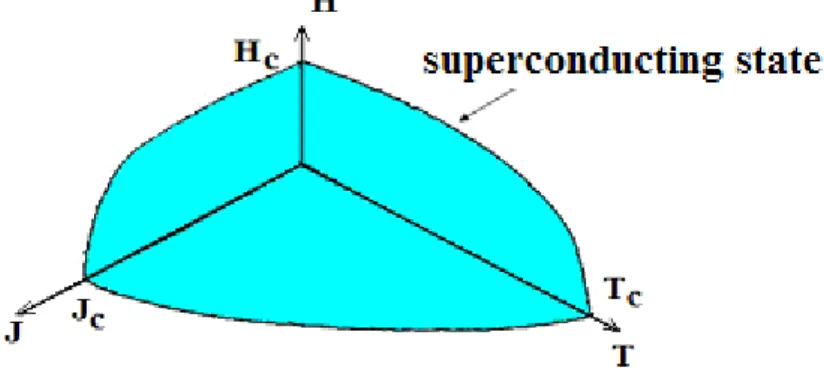
1. Superconductivity ... 33
2. The critical current ... 34
3. Purpose of the measurement ... 35
4. Measurement tasks ... 35
5. Fundamentals ... 35
6. Execution of the measurements ... 36
7. SUPERCONDUCTING FAULT CURRENT LIMITER ... 38
1. Objective ... 38
2. Defining terms and theoretical background ... 38
3. Tasks ... 38
4. Principle of the measurement ... 39
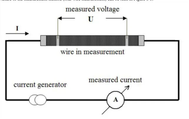
5. Carrying out of the measurement (measuring method) ... 40
6. Recording the results ... 41
7. Modeling of the normal operational condition (shorted secondary circuit) ... 41
8. Modeling of the fault condition (reactance) ... 41
Four-Quadrant Thyristor DC Drive
9. Measurement of the superconducting FCL (overload) ... 41
10. Measurement of the superconducting FCL (short circuit) ... 42
11. Evaluation ... 42
12. Conclusions should be done by the students on the base of the obtained results. ... 42
8. Measurement of a flywheel energy storage device with high temperature superconducting bearings 43 1. Introduction ... 43
1.1. Superconductivity ... 43
1.2. Flywheel energy storage ... 44
1.3. Flywheel energy storage system with superconducting bearings ... 46
1.4. Superconducting bearings ... 47
2. Goal of the measurement ... 47
3. Measurement tasks ... 47
4. Theoretical basics of the measurement ... 47
5. Execution of the measurements ... 48
6. Literature ... 49
9. Villamos gépek és hajtások labor II. ... 50
1. Aim of measurement ... 50
2. Theory ... 50
2.1. Operation of solar cells ... 50
2.2. Operation of fuel cells ... 51
3. Measurement guide ... 52
3.1. Circuit diagram for solar cell measurement ... 52
3.2. Circuit diagram for ful cell measurement ... 52
3.3. Instruments used ... 52
4. Measurements ... 52
4.1. V-I and P-R characteristics of a solar cell ... 52
4.2. V-I characteristics of a fuel cell ... 53
4.3. V-I characteristics of electrolysis ... 53
4.4. Additional measurements ... 53
5. Check your knowledge ... 53
1. fejezet - Four-quadrant Thyristor DC drive
1. Introduction
Thyristor DC drives are nowadays commonly used in the paper industry in the field of reeling drives.
Traditional field of application are high power controlled centrifuge drives (food industry), extruder drives in rubber and plastic industry. The above mentioned applications are characterized by need of controlled torque in addition to speed control. Technological requirements usually include both driving and braking i.e. motoring and generating torque capability of the drive, in certain cases with speed reversal.
The power component of controlled DC drives is typically three-phase thyristor bridge converter with firing angle control, while the electromechanical component is a DC motor with separate (constant) or compound (mixed) field excitation.
In the frame of recent laboratory practice we study electrical features of a pair of mechanically coupled controlled DC drives, both are supplied by own thyristor converter. One of the drives works as motor with active power consumption, while the other works as generator, returning the brake energy back to the line.
2. Terminology and keywords
Power electronics, Converters AC-DC, Firing control, Controlled drives, Energy conversion
3. Laboratory practice target
1. Review of the MENTOR-II type four-quadrant thyristor converter's technical features, including principle of operation, basics of program settings and adjustments
2. Measurement and oscilloscope analysis of AC and DC side electrical quantities in different operating conditions (in all four quadrants)
3. Study the dynamic behavior of the drive arrangement under test by means of oscilloscope signal analysis 4. Evaluation and interpretation of the results in form of measurement protocol
4. Theoretical basis of the measurement practice
4.1. Structure of the three-phase thyristor converter
Thyristor converters, as typical, are built in three-phase bridge configuration. The base arrangement is the three- phase diode bridge (rectifier) see fig. 1. Its operation, specific voltage and current waveforms are presented and analyzed in detail in Lit. [4] Pp.175†178.
Four-quadrant Thyristor DC drive
Figure 1. Three-phase Diode Bridge
Advantage of the three-phase diode bridge arrangement is the simplicity and tolerable distortion factor of the line current (waveform is not far from sinusoidal fundamental), as it can be seen on Fig. 2
Figure 2. Rectified voltage Ua and input phase voltage/current Lit. [4]
Output voltage of diode rectifier cannot be influenced electronically, diode‟s conduction state changes in the moment of the natural commutation.
4.2. Phase angle control of thyristor converters
Thyristor is the first semiconductor structure, used as power switch component. It can be switched on by small power gate signal, while switch-off cannot be achieved by gate control. Principles of operation can be found in Lit. [4] pp. 14†16.
Three phase thyristor converter circuit, feeding an ideal DC machine, (with all protection components) can be seen in Fig. 3. Output voltage Ud (mean value Ud0) can be controlled by delaying thyristor gate pulses, influencing their conduction period. Gate pulse delay should be fixed to the moment of natural commutation (moment of beginning of diode conduction state), i.e. gate control is to be synchronized to the line. Method is known, as firing angle control, typical one-phase waveforms and quantitative relationships found in Lit. [4]
pp.20†24.
Figure 3. Thyristor converter, feeding an ideal DC machine
Four-quadrant Thyristor DC drive
Disadvantage of the phase angle control is the phase shift of the input line current fundamental, resulting in an excess reactive power (Lit. [3] Chapter4.2.3.). Line power factor is a function of actual operating point of the drive.
Thyristor converter, feeding a DC motor with armature voltage Ua, provides one-polarity current Ia>0, and two- polarity output voltage Ud. In case converter operates in rectifier mode (Ud0>0), machine works, as motor (see Fig.4., I. Quadrant), while inverter mode of converter (Ud<0) results in machine, working as generator (Fig. 4., II. Quadrant).
Three-phase converters are sensitive to input voltage phase sequence. Thyristor S1-S3-S5 on Fig.5. should be fired in time sequence accordingly to that of input phase voltages VR-VY-VB. Reversed phase sequence results in loss of control and malfunction of converter.
Specific feature of inverter mode operation in thyristor converters is the danger of the loss of commutation. In inverter mode of the converter, conducting thyristor can be switched off only by firing the next in sequence element (line commutation), unless conducting device will connect line voltage with motor armature voltage Ua<0. As result, a high surge current gets on (inverter turn-over), the overcurrent can be cleared only by fast- acting input blow fuses (F1†F3 on Fig. 3.)
Figure 4. Four quadrant and energy flow direction of DC drive
Principle of operation, time functions of voltages and currents of converter can be studied by means of Three- Phase Full Bridge and Four-Quadrant Converter simulation program at [7]
http://www.ipes.ethz.ch/ipes/e_index.html web site.
4.3. Electric stresses and protection elements in Thyristor Converters
Semiconductor crystal structures of thyristors are extremely sensitive to shortest (in order of μsec and less) electric stresses. Converter power circuit on Fig. 3. include usual protection components of thyristors. Absolute maximum values of thyristor stresses, not to be exceeded, are:
1. Umax : maximal peak value of anode-cathode voltage in forward and reverse direction. It can be limited by suppressor elements (varistors) V1†V6.
2. dU/dt: maximal rate-of-rise of forward voltage, should be limited by parallel R-C suppression networks 3. tq: turn-off time, needed thyristor structure to be switch off. Turn-off time should be ensured by inverter-
mode firing angle limitation.
4. dI/dt: maximal rate-of-rise of thyristor current, when switched on. This value can be limited by L2†L4 line side (commutation) chokes
5. Is: Maximal surge current, usually defined for half period of line voltage (once fired thyristor cannot be switched off within voltage half period)
Four-quadrant Thyristor DC drive
For over-current protection in circuits with DC voltage component (like DC thyristor converters), limitation is given in form of I 2 t integral for fusing. Fast-acting fuses F1†F4 are chosen to ensure fusing I 2 t value less, then the limiting value of the thyristors.
4.4. Anti-parallel thyristor converters, working without circulating current
Motor armature current is negative (Ia<0) in the III. and IV. quadrants according to Fig. 4. Negative armature current can only be supplied by adding a negative converter (anti-parallel converter, Fig. 5.)
Figure 5. Four Quadrant DC Drive with anti-parallel Converters [1]
Output DC voltage mean value of three-phase bridge thyristor converter is a cosine function of the firing angle(
Lit.[2] pp. 140).The positive and the negative converter would give reverse each other output voltages, if having equal firing angles. Therefore the two converter should have so called “complementary” phase-angle control (αneg=180°-αpos). When positive converter have minimal phase angle α~0, the negative converter have maximal phase angle α~180°. Technical solutions of Four-Quadrant DC Drives are discussed in Lit. [3] Chapter 2.4., and in Lit [5] Chapter 2.2.1.
In present test arrangement MENTOR-II type thyristor converters are used. They have structure, similar to that, shown in fig. 5. Circulating currents are excluded by control logic. At any moment only one (positive or negative) converter is enabled, depending on desired DC current direction. Simultaneous current flow of both converters would lead to line phase short circuit to be avoided.
4.5. Control methods of DC drives
Simple and widely used control structure of DC drives is armature voltage regulation with internal closed loop armature current control [5] pp. 9-10. There is no need of external sensors, and torque regulation/limitation can be achieved in most cases.
Closed loop control of armature current include phase angle control of thyristors, therefore current loop should be regarded, as dead-time, sampled, non-linear system. Continuous and discontinuous current conducting modes of converter result in different transfer function coefficients, requiring adaptive control.
Above mentioned control tasks are solved in a μP based digital controller by software way. Control loop parameters for actual motor will be determined and saved automatically by preliminary “self test” procedure.
Regulation of the armature voltage results a near constant speed operation of the drive, assuming, that excitation field is constant, motor is compensated, and torque is below the limiting value (speed-regulated drive)
Regulation of the armature current is often used in applications, demanding closed-loop control of the motor torque (torque-regulated drive). In case of accelerating torque in the selected quadrant, motor maximum speed must be clamped at a limit value [6]. MENTOR User Guide can be found at http:// www.controlvh.hu web site.
Four-quadrant Thyristor DC drive
Typical control algorithms of thyristor converter fed DC drives, and their linearized models are discussed in details in Lit. [5], Chapter 2.2.1.
5. Laboratory test arrangement
5.1. Structure of DC machine set
Two-machine set consists of two compensated type DC motors, with external excitation, linked mechanically with elastic coupling. Motors are fed by similar type MENTOR-II Thyristor Converters, but have different regulating features.
In accordance with Fig. 6., speed of the machine set is determined by Drive1 speed reference, while torque between the two machines will be adjusted by Drive2 torque reference. Arbitrary working point within maximal values of armature voltage and current can be adjusted for investigation.
Figure. 6. Mechanical speed-torque characteristics of drives under test
In operating point “A” (Fig. 6.) Drive1 works, as motor. Active power, fed by Drive1, will be returned back to the line by Drive 2, working, as generator (brake machine).The rotation directions of the motors are reversed.
Nominal values of machines G1, G2:
1. Un=220 V armature voltage 2. In=37 A armature current 3. Pn=8 kW Electric power 4. nn=1500/min rotation speed 5. Ign=1 A excitation current 6. La=~8 mHy armature inductance 7. Ra=~0.3 ohm armature resistance
5.2. MENTOR DC drive: structure and main parameters
Power schematics are identical to anti-parallel converters, shown on Fig. 5. Measurements of internal quantities are measured by sensors (Voltage, current, temperature, etc.), with digital signal processing. The main technical data of converter:
1. Type: MENTOR M45R
Four-quadrant Thyristor DC drive
2. Manufacturer: Control Techniques/Emerson
3. Structure: Four-quadrant drive with anti-parallel thyristor converters, μP controlled 4. Input voltage: 3×200 V†3×480V AC 42†60 Hz, false phase sequence protected 5. Input current: 3×38 A continuous, 150% max. overload
6. Power factor: 0†(±0,90)
7. Output voltage: ±270†600V DC, depending on line voltage range 8. Output current: 45 A continuous, 150% overload
5.3. Functions of the control system
Main functions of the control system are:
1. Digital data processing of signals, gathered from internal and external sensors (Voltages, currents, speed, position, temperature, etc.)
2. Closed loop digital regulation, according to control strategy, including complex thyristor firing angle control 3. Configuration and data processing of inputs and outputs
4. Operation of local keypad, displays, serial communication ports 5. Monitoring tasks, alarm and trip functions, diagnostics
5.4. Operators’ menu system of parameters
Nowadays almost all technical features of controlled drives can be adjusted by software. Industrial drives are intended to cover widest variety of possible applications. MENTOR-II, used in recent test equipment, has similar, highly flexible software. Block diagram of controller structure consists of elements, for the most part freely adjustable by user.
MENTOR-II controller has a lot of user definable/readable elements, called, ”parameter”, in amount exceeding 400. Parameters are divided into functional groups, named “menu”. MENTOR has 13 menus, each containing 20†39 parameters. The role of parameters and their connections are presented on partial flow-charts of the selected menu. [6]. Parameters can be divided into groups by their content, too:
1. Read-only digital variables: (measurement results, controller outputs, manufacturers fixed settings)
2. Adjustable digital variables: (references, limiting and min/max comparison values, closed loop parameters, security codes, source and destination parameter data)
3. Programmable logical variables – configuration bits (control structure, input/ output, communication, monitoring system configuration)
Generally used base configurations are programmed by manufacturer in form of default parameter set, to reduce the number of parameters to be programmed in applications without high requirements and complexity. If needed, three level security code protection systems can be used against non-professional handling attempt.
Laboratory test equipment demands only 10†15 parameters to be adjusted.
5.5. Drive control from local control panel
Laboratory tests demand manual control and adjustment of the drives. Therefore a minimal configuration control panel was built up, in accordance with Fig. 7. input/output control connections:
1. K1: Enable/disable (TB4/31) switch can disable system operation (in case for example power-on) 2. K2: Star/stop (TB3/21) Switch permits running (forward or reversed) of the motor
Four-quadrant Thyristor DC drive
3. K3: +10V/-10V polarity change of the potentiometer adjusted reference (speed or torque) 4. P1: Ua armature voltage reference at (TB1/3) fixed input (±10V range)
5. P2: Ia armature current reference at (TB1/4) programmable input (±10V range)
Figure 7. Control inputs and outputs
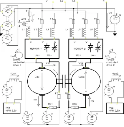
5.6. Schematics of test arrangement and measuring instruments
Schematics of power parts and fix connected instruments presented on Fig.7. Input line phase voltages L1-L2- L3 are 3×120/200 V AC
Figure 8. Test arrangement
Specification of measuring instruments, as follows:
1. Uin: electrodynamic voltmeter in range 127 V AC (phase voltage )
Four-quadrant Thyristor DC drive
2. Iin: electrodynamic ammeter in range 5 A (line current, transformed) 3. Pin: electrodynamic watt-meter U=127 V, I=5 A (one-phase active power)
4. Qin: electrodynamic watt-meter u=240 V, I=5 A (one-phase circuit for measuring reactive power) 5. AV1: 50 A/5 A AC current transformer (10:1 current ratio)
6. V1,V2: analog DC voltmeters in range 300V
7. A1,A2: analog DC ammeter, suited to 60 mV precision current shunt 8. RS1-2: 50 A/60 mV laboratory current shunts
9. PS1-2: HPH type excitation units 0†2.5 A
10. DSO: digital storage oscilloscope Goodwill GDS-1062, two channel, USB communication 11. PHA: FLUKE 41B one-phase power analyzer, with isolated data cable to serial port 12. CCL: FLUKE i310s AC/DC current clamp 30 A, 10 mV/A
13. DPR: TESTEC TT.SI9002 type high-voltage isolated probe 1:200, max. ±1400 V 14. PC : computer with communication and data processing SW
6. Laboratory test tasks
6.1. Measurement of converter line-side parameters in motor and generator mode
1. Be sure, drives are disconnected from mains. Put K1= disable; K2=stop; K3=+ positions, P1,P2 to minimum.
Connect voltage probes of PHA analyzer to phase voltage U1, current clamp CCL put to measure phase current I1.
2. Switch on power mains, and control nominal excitation currents. Enable both drives to run by K1=enable, then K2=start switchover.
3. Adjust Drive1 speed reference to nominal armature voltage with P1, when running, increase torque, developed by Drive2 to 75% of nominal armature current with P2 of Drive2. Read and fix input quantities (Uin, Iin, Pin, Qin), measurement data of power analyzer save to internal memory.
4. Repeat measurement in 8 working points with decreasing armature voltage in range of forward nominal to reversed nominal with zero seed excluded. When finished, stop machines with K2=stop, after machines have stopped, suspend operation by K1=disable.
6.2. Oscilloscope waveform analysis of converter motor-side variables
1. Connect oscilloscope to PC/USB port, and get software started. Connect DPR adapter inputs to converter DC output Ua (CH1), CCL current clamp put to measure DC current Ia (CH2). Switch oscilloscope to line synchronization.
2. Similar to pp. 1.6.1, set the first operating point of the drives. Read and fix input quantities (Uin, Iin, Pin, Qin), as well, as DC quantities (V1, A1, V2, A2).Save waveforms of Ua, Ia on PC. Define effective and peak value of AC components by means of built-in measurement menu both for armature voltage and current.
3. Repeat measurement at minimal speed (~10% of nominal), and in reversed nominal voltage, then return to the first operating point.
Four-quadrant Thyristor DC drive
6.3. Oscilloscope waveform analysis of voltage at phase-angle control
1. Study output voltage waveform Ua , scanning the full available range. Save to oscilloscope internal memory the output waveform with minimal firing angle to estimate moment of natural commutation. Set Ua=100 V, then compare on-line waveform with the reference saved previously. Measure firing angle delay, relative to natural commutation moment by time cursor.
2. Determine the commutation process feature on output voltage waveform. Measure the commutation period time at Ua=nominal, and Ua=50 V by time cursors. Document results on PC.
6.4. Analysis of torque reversal transient process
Set Ua=nominal, Ia= 0.75 x nominal operating point. Investigate on oscilloscope the transition of armature current, when switchover Drive2 torque by K2 from positive to negative and back. Current direction change require changeover of positive and negative converter operation. Fix and save armature current transition, measure the dead time between the active state of the two converter. Document results on PC.
7. Evaluation and documentation of test results
1. Document test arrangement with measuring kit specification
2. Define total apparent, active and reactive power of the converter in based on results of pp. 1.6.1. Include power factor (P.F.), measured by power analyzer. Build up the diagrams in function of armature voltage. Explain the results.
3. Calculate power losses of the machine group and converter Drive1 on the base of results of pp. 1.6.2. at nominal and minimal speeds. Identify the sources of the losses. Document AC component measurements and waveforms. Which of them will greatly affect DC motor operation, and why?
4. Determine firing angle of converter at Ua=100V, using result of pp.1.6.3. Compare experimental result with theoretical, calculated for actual U1 input phase voltage.
5. Determine dead time of armature current in pp.1.6.4. What is the reason of it? Which quadrants are affected by this phenomenon?
8. Control questions and tasks
1. Calculate minimum of supply AC voltage to ensure nominal armature voltage for the machine in test equipment
2. On Fig. 6. horizontal axis is common for both speed “n” and voltage “Ua” , vertical axis is common for both torque “M” and current “Ia”. Explain theoretical base, why it can be done. What is neglected?
3. Determine and represent ideal-case input current waveform of three-phase diode rectifier when output current Ia, output inductance L=∞, commutation neglected. Calculate effective values of input current and its fundamental too. Calculate distortion factor of input current.
4. Let Drive1 of test arrangement operating in quadrant III. Supposing steady-state, where is the operating point of Drive2 and why?
5. Converter under test is supplied from 3×127/220 V three-phase voltage with grounded neutral. Output voltage is analyzed by line-connected grounded equipment. Determine the isolation voltage of the input voltage probe adapter at maximal converter output voltage.
9. Literature
x
Four-quadrant Thyristor DC drive
[1] Dr Halasz, S. (1989). Automatizált villamos hajtások. Budapest: Tankönyvkiadó.
[2] Dr Halasz, S. (1993). Villamos hajtások. Budapest: Egyetemi tankönyv.
[3]Dr. Puklus, Z. (2007). Teljesítményelektronika. Győr.
[4]Dr Schmidt, I. Dr Veszpremi, K. Hajtásszabályozások (BMEVIVEM175.). TÁMOP 2011.
[5] Venkat Ramaswamy Univ. of Sidney (2011. 07) http://services.eng.uts.edu.au/~venkat/pe_html.
[6] MENTOR Manual (2003). Control Techniques Drives Ltd.
[7] http://www.ipes.ethz.ch/ipes/e_index.html.
2. fejezet - Measurement of a synchronous servodrive with trapezoidal field
1. Scope of the measurement
AC drives becoming more and more important in the field of robot and machine tool control. In case of permanent magnet synchronous machines (PMSM) both machines with sinusoidal and trapezoidal field are applied. Last is often referred as brushless DC (BLDC) due to its similarities in commutation to the traditional DC machine.
Optimal control can be only achieved in both sinusoidal and trapezoidal case, when current vector control is applied, and the current vector is matched to the position of the rotor, to the shape of the field and to the torque required. This can be performed by using transistor based voltage inverters with pulse width modulation (PWM). In this measurement a machine with β=180° trapezoidal field will be investigated.
2. Theoretical background of the measurement
2.1. Supply of synchronous machines with trapezoidal field
An appropriate current waveform (matching the above requirements) can be chosen by knowing the pole voltage as a function of rotor angular position. Mechanical power and hence also the torque produced by one single phase can be calculated as the product of the pole voltage and the given phase current. According to this, constant power and torque can be achieved if the sum of the pole voltage and phase current products of all the individual phases is constant. For machines with trapezoidal field some types of current waveforms can be used.
The simplest supply is the so called one phase supply. In this case – neglecting the current overlapping during the commutations – there is always only one phase is carrying current. Positive torque can be produced by applying a positive current in those rotor angular position regions, when the pole voltage is positive. Matching in this case means that the current is constant when the pole voltage is also constant. This occurs in certain regions only when the speed is constant as well. Anyway, the pole voltage-rotor position function also has negative regions as well. This part is not utilized in one phase supply. It can be said that this kind of control has only one advantage compared to the two phase supply that the phase currents are flowing only in one direction, only unipolar supply is required. This is very similar to the supply of DC machines, with the difference that in this case the DC current is being carried by not only one, but three different windings, and the commutation is forced by an electronic controller instead of a mechanical device called commutator. Hence these drives are often referred as electronically commutated DC (ECDC) drives.
If one would like to utilize the negative regions of the pole voltages as well, then here constant, but negative currents should be applied to achieve a positive torque again. Hence, unlike in case of one phase control, bidirectional current flow is needed for each of the phases, which requires bipolar supply. In this case – neglecting the overlapping again – there are always two phases are carrying currents out of the three.
It is also possible to perform three phase conduction, when at a given time moment, all the three phases are carrying currents, however this is not used in practice.
In case of one- and two-phase supply, the main goal is the simple controllability even if it means that the idealized current waveforms can only be implemented with some errors in practice. Hence the torque with these drives is less smooth. When a smooth torque is critical, then machines with sinusoidal field are applied.
2.2. Current control of synchronous machines with trapezoidal
field
Measurement of a synchronous servodrive with trapezoidal field
Current control of synchronous machines with trapezoidal field can be realized in more ways: hysteresis control in individual phases, hysteresis control on the basis of a lookup table and PI current control with pulse with modulation.
3. Introduction of the measurement
3.1. Main components of the drive being studied
1. Synchronous servo drive (manufactured by Stromag):
Synchronous servo electronic controller: Umax=3∙240 V, In=25 A, Imax=50 A
Synchronous servo motor: Mn=8 Nm, In=20 A, Imax=105 A, K=0.4 Nm/A, Θ=0.006 kgm2, nmax=3000/min.
1. Load machine:
Mn=20 Nm, In=25 A, Imax=170 A, K= 0.8 Nm/A, Θ=0.032 kgm2, nmax=1200/min.
1. Transformer, 3×380/3×210 V, 2 kVA 2. Torque meter
3. Oscilloscope 4. Load resistor
3.2. Startup of the drive
1. Turn off the reference signal switch of the electronic controller, set the reference potentiometer to zero, and turn off the enable switch.
2. Turn on the 3×400 V 50 Hz connection
3. Enable the drive by the enable switch, set the desired reference signal and turn on the reference signal switch.
3.3. Applied metering devices
1. Torque meter 2. Handheld multimeter
4. Measurement tasks
4.1. Measurement of the pole flux and pole voltage
Disable the electronic controller, and speed up the synchronous motor by the DC load machine connected to its shaft. Investigate the space vector (Park-vector) of the pole flux and pole voltage and the time functions. Explain differences from theoretical (idealized) shapes. Verify the rightness of the mechanical connection between the position encoder and the synchronous machine. This can be done on the basis of la and lb position signals.
4.2. Investigation of voltage, flux and current
Connect the DC load machine to the RT load resistor. Operate the synchronous machine as a motor, and investigate the u, Ψ, and i vectors and the ua, Ψa, ia phase quantities in both rotational directions. Determine which kind of supply is used in this device.
4.3. Investigation of synchronization
Measurement of a synchronous servodrive with trapezoidal field
Verify the synchronization (matching) of the currents to the rotor position on the basis of la, lb and the ia signals for both rotational directions and for both motor and generator modes. Generator mode can be achieved only in transient state. Explain the differences of synchronization between motor and generator modes. Investigate the synchronization during a transient from motor to generation mode.
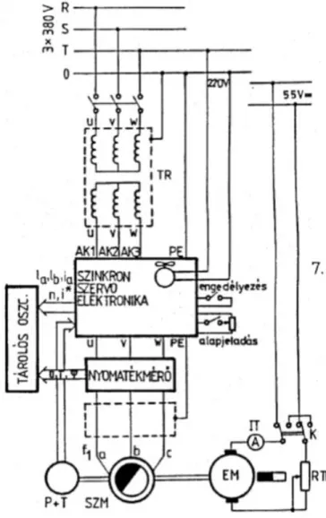
Figure 1: Schematics of the measuring system
4.4. Verification of the speed metering
Verify the operation of the speed metering electronics in both rotational directions on the basis of the la, lb and n signals!
4.5. Measurement of the torque-speed curve of the drive
On the basis of the torque signal of the torque meter or on the basis of the dc current of the load machine, take the torque-speed curve of the drive. Explain the results!
4.6. Investigation of time functions of speed and currents
Investigate the n(t) and i(t) curves of the drives at step changes in the reference signal and at reversals by using the oscilloscope! Perform the measurement both with and without load.
4.7. Investigation of the effects of step changes in the load
Investigate the effects of both positive and negative step changes to the n(t) and to the i(t) functions!
Measurement of a synchronous servodrive with trapezoidal field
4.8. Investigation of reference signal following abilities
Apply a signal generator! Set a constant reference signal, and add a sinusoidal, then a square signal to it.
Investigate the signal following abilities of the drive on the basis of na(t), n(t) and i(t). Take the Bode-diagram (both amplitude and phase) of the closed control circuit.
5. Investigations with computer simulations
The simulation investigates the control loop of a drive with a β=180° synchronous servo motor. The matching rules should be kept also for the transient states. In these states, the magnitude of the pole voltage changes proportionally with the speed. The value of the current reference signal is determined by the torque requests of the outer speed control loop.
5.1. Hysteresis current control in individual phases
For this method, a current reference signal is required for each phases, and deviations are calculated in each phases. Tolerance bands (±ΔI) determines the allowable deviations from the reference signal. When the tolerance bands are the same for all three phases, then in a vector diagram, it defines a hexagon with 2ΔI distance between its opposite sides. Simulation shows, that in this case, the current vector remains within this hexagon, except in two cases:
1. Sometimes into the triangles neighboring to the sides. The reason of it that the star point of the machine is floating; hence the three currents cannot be controlled independently.
2. In every 60 electrical degrees with a big overshoot. The reason of it that the reference signal jumps in every 60 degrees, which cannot be followed by the current immediately because of the inductances of the machines.
5.2. Current vector control based on a lookup table
The controller senses when the current error vector reaches one side of the tolerance hexagon. The necessary switching state of the inverter is determined by a lookup table value. This value depends on two things. Firstly, which side of the hexagon was reached, and secondly, which is 60 degree sector contains the voltage vector affecting the change of the error. The simulation shows, that the current vector with this method always remains within the tolerance hexagon with no exceptions.
5.3. Analogue PI control with PWM
Parameters of the PI controller can be varied from the simulation software. The inverter controller switches the appropriate voltages to the appropriate in every 60 degrees.
5.4. The simulation program
The program is written in Pascal language. The system is described by its state equations. Solution is found by a Runge-Kutta method. The points of intervention are determined by an iterative process.
The initial conditions and parameters can be varied by V, simulation can be started by G. Plots can be made by A, and exit is possible by K. When starting the simulation, the simulation time and the control method have to be selected. One has to define the tolerance band and the drawing mode.
It is possible to investigate the time function of the current vector or the current error vector (magnified). At the end of the simulation, it is possible to post-process the stored data, or to plot different quantities like phase currents, speed, torque, etc. The default integration step is 0.05, which means 159 µs. The relative time scale can be converted to real according to the following equation: trelative=wntreal, where wn=314 rad/s.
6. Test questions
1. What kind of electrical machines are applied in servo drives?
Measurement of a synchronous servodrive with trapezoidal field
2. What kind of supply modes are commonly used for trapezoidal field machines?
3. Why synchronous machines with trapezoidal field are ofter referred as ECDC machines?
4. How to calculate the torque of synchronous machines with trapezoidal field?
5. What is the pole voltage, where and how is it possible to measure?
6. Why there are always some torque ripples in case of synchronous machines with trapezoidal field?
Questions to think about
1. What kind of drives operates with unipolar (unidirectional current) supply?
2. What are the advantages and disadvantages of unipolar supply?
3. In case of which unipolarly supplied machine is it possible to increase the torque by driving the iron core to saturation?
7. References
[1]
Istvan Schmidt, Gyulane Vincze, Karoly Veszpremi: Electric servo and robot drives, Műegyetemi Kiadó, pages 75-83 and 92-99, Budapest 2000 (in hungarian).
3. fejezet - Measurement of a synchronous servo drive with sinusoidal field
1. Scope of the measurement
AC drives becoming more and more important in the field of robot and machine tool control. In case of permanent magnet synchronous machines (PMSM) both machines with sinusoidal and trapezoidal field are applied. Last is often referred as brushless DC (BLDC) due to its similarities in commutation to the traditional DC machine.
Optimal control can be only achieved in both sinusoidal and trapezoidal case, when current vector control is applied, and the current vector is matched to the position of the rotor, to the shape of the field and to the torque required.
The purpose of the measurement is to familiarize an industrial purpose synchronous servo drive. The drive is fully digital and masterminded by a microcontroller. The control level is selectable. It can be operated in position or in speed control mode. Speed control is active in both cases, as control loops are cascaded. The innermost loop is the current control loop, which consists of a digital, three phase PI type controller and a puls width modulator. The drive can be operated from a PC, parameters are adjustable, and also graphical representation of different quantities is possible. The reference signal can be a voltage (potentiometer) or a frequency (function generator) level. During the measurement, both control of the drive and investigation of the results are done by using a personal computer.
2. Theoretical background of the measurement
2.1. Supply of a synchronous machine with sinusoidal field
An appropriate current waveform, matching the machines magnetic field shape can be chosen on the basis of the pole voltage as a function of angular position of the rotor. Mechanical power and hence also the torque produced by one single phase can be calculated as the product of the pole voltage and the given phase current. According to this, constant power and torque can be achieved if the sum of the pole voltage and phase current products of all the individual phases is constant. In case of synchronous machines with sinusoidal field, the sinusoidally distributed rotor field can be described by a pole flux Park vector, which rotates together with the rotor, when looking from a stationary coordinate system. In an idealized case, the magnitude of this pole flux vector is constant. In case of a constant speed, the pole voltage induced by the pole flux is constant and also sinusoidal.
The Park vector of this voltage is also rotating with a constant speed. For a constant mechanical power and torque, a three phase sinusoidal current system is needed with a frequency equal to that of the pole voltage.
Actually in case of synchronous machines with sinusoidal field, the matched supply means sinusoidal currents synchronized to the angular position of the rotor. Best servo features can be achieved by a current vector control, which keeps the torque angle (the angle between the current and the pole flux) at ±90°. The servo drive of this measurement performs such a control throughout the whole speed range. This control is often referred as normal (not field weakening) mode. An ideal current vector controller ensures the above angle even in case of transients (startup, reversals, etc).
2.2. Current control of synchronous machines with sinusoidal field
Current control of synchronous machines with trapezoidal field can be realized in more ways: hysteresis control in individual phases, hysteresis control on the basis of a lookup table and PI current control with pulse with modulation.
3. Introduction of the measurement
Measurement of a synchronous servo drive with sinusoidal field
3.1. Main components of the drive being studied
1. Synchronous servo drive (manufactured by SEM, England):
Synchronous servo electronics: Umax=3∙380 V, In=5 A, Imax=10 A
Frequency of PWM is 9.26 kHz. Current control and a pulse width modulation is performed by an ASIC NOVOCHIP developed by NOVOTRON, other tasks are performed by a Hitachi H8 microcontroller.
Evaluation of the resolver signals is done by a 2S82 Analog Devices IC.
Main parameters of the digital control:
1. Current control: PI type, cycle time is 54 µs, 2. Speed control: PI type, cycle time is 432 µs, 3. Position control: PD type, cycle time is 432 µs.
Sychronous servo machine: Mn=3.8 Nm, Inrms=4 A, Imax=24 A, K=64 V/1000 rpm=0,611 Vs/rad, nmax=6000 rpm.
The „K” constant means that e.g. at the 6000 rpm maximum speed the peak value of the line to line pole voltage is 384 V. In this case the no load phase voltages at the terminals are 221.7 V peak. The supply is connected directly to the 3×400 V, 50 Hz grid, hence the voltage level of the inner DC link is about 560 V. The inverter can produce a peak phase voltages, which means that it can operate the machine at maximum speed without field weakening.
1. Load machine (EZG703 DC machine, manufactured by EVIG, Hungary):
Mn=3 Nm, In=13 A, Imax=80 A, K=0.24 Nm/A, Θ=0.00192 kgm2, nmax=2500 rpm.
1. Torque meter: for torque metering and it also provides Park vector components of voltages, currents and flux.
2. Oscilloscope 3. Load resistor
3.2. Startup of the drive
1. Turn on the 3×400 V, 50 Hz grid. The device performs a self-test following it. On the display, the 1,2,..,9 numbers and a flashing u letter indicates the standby.
2. The software for the drive can be started by ND21.com-mal, which is found in a directory with the same name. Menu options are shown in the left part of the screen, after start, it is the main menu. In the right part of the screen a coordinate system appears, showing its timescale, and the quantities to plot. In the right bottom corner, there is an error message, which can be erased by DEL. Instead of it the temperature of the motor can be seen, if there is no error. In the top right corner, there is a message indicating the present state of the drive. Some examples are:
3. The main menu contains the following items:
To choose an item, one has to press the key in the bracelets; step back is possible by pressing the r button or SPACE.
3.3. Usage of the drive
Basic settings of the drive [G] should not be modified. For the first trials, set the limitations [M] to low values.
Setting of speed control is possible from the main menu [D] and from demo [d] as well.
Choosing the [D] menu point, gives a big help in appropriate setting of the speed controller, as it makes possible to observe the reactions of the drive in test mode for reference signal steps, reversals and cyclic reversals.
Measurement of a synchronous servo drive with sinusoidal field
Reference signal steps [Drehzahlsollwert] can be set by [N] or [n], reversal is possible by [d]. The cycle time of the test mode can be set by [T]. The reference signal should not be changed during the runs!
The drive can be started by [g] and can be stopped by [s]. In case of an error or unexpected event, it can be disabled by [Esc].
From [d] point of the main menu, the type of control can be selected. This can be speed [d] or position [p].
Positioning tests can be started also from here by [a].
Parameters of speed control can be set in the [d] menu point of the main menu. These are the reference signal [n], the ramp time [a], the maximum speed [N], the maximum current [i] and the [d] rotational direction. This last can be set by a + or – sign, while the others require decimal values. If speed control was previously set to test mode from [D] menu point of the main menu, then it can be overridden by [R].
Parameters for position control are: the position reference signal step [x] (in mm dimension), the length of one full revolution [*] (in mm dimension), the speed of the motor [n], which means the speed of the desired positioning, and the ramp of the speed [a], which prescribes the acceleration. [i] determines the direction of positioning. When a too high speed is given to the speed of positioning, the drive stops with an „Überlauf”
signal.
Controller parameters can be set at [p] menu point of the main menu. Here it is possible to filter the speed signal, and to set P and I parts of the speed controller and P and D parts of the position controller. Settings can be seen as hexadecimal values and in percents from a graph. When one operates the drive in speed control mode, settings of the position controller (Lageregler) can be turned off by [@].
Choosing [o] in the main menu takes us to the oscilloscope submenu. Here it is possible to set two signals to plot (any of the phase currents, speed, position or torque, and also their reference (Sollwert) or feedback (Istwert) signals). Trigger level can be also set, as well as step up or step down edge sensing. One can choose the time base as well. Contents of the screen can be stored by [h] (hold). Settings are valid only if the switch [a]
is in „yes” state. The drawbacks of the oscilloscope function are the low resolution and the fixed vertical scale.
The oscillographs can be stored into directories.
By [a] menu point of the main menu it is possible to adjust inner parameters (RAM, EEPROM, ASIC) of the system. RAM parameters can be named according to the RAM-Monitor. Writing and reading is done through hexadecimal values. The parameters of the current controller can be set among the parameters of ASIC [A]. The proportional part can be set by [p] and the integration part by [i] (both are in hexadecimal values).
3.4. Applied metering devices
1. Computerized data acquisition and processing system 2. Torque meter
4. Measurement tasks
4.1. Introduction of the drive
Getting started with the drive. Practice the reference signal definition, mode selection, setting of the oscillioscope functions, etc.
4.2. Veirification of the EMK compensation, setting of the current controller
From the [G] submenu of the main menu, verify the setting of the EMK (pole voltage or back EMF). This should be 64V/1000 rpm (64mV/Umdrehung)! Following this, set the current controller in a speed controlled test mode. Eg. set the oscilloscope to the iasoll, iaist signals, with nsoll trigger signal with, -1 delay and 5 ms time base. Basic setting of the current controller is P=C0H and I=02H. Good settings result in minimal phase delay and no overshoots.
Measurement of a synchronous servo drive with sinusoidal field
4.3. Settings of the speed controller
Here it is also advised to do the settings in test mode. The oscilloscope settings should be eg. nsoll with nist trigger signal and 200 ms time base. In the [p] menu point of the main menu vary the parameters of the controller. The goal is to achieve a fast convergence with minimum overshoots.
4.4. Settings of the position controller
The settings of the position controller should be done also in the [p] menu point of the main menu with
„Lageregler: ein” (position control: on) state. It has to be taken into account that the position encoder resets itself after every full revolution. Hence the position signal is a saw signal instead of being continuous. The position reference signal should be also like this. Let‟s try to make such position steps, when this plotting mode is not too annoying. It is recommended to set the oscilloscope signals to be lagesoll, lageist, the trigger signal should be lagesoll, and the time base should be between 100 ms and 200 ms. One should achieve positioning without overshoots with good settings.
4.5. Investigation of Park vectors
By using the torque meter, one should investigate the Park vectors of the voltage, current and flux.
4.6. Investigation of dynamic properties of the drive
Investigate the startup and reversals of the machine on the basis of Park vector generated by the torque meter.
Compare the measured and the simulated values!
5. Investigaton of results simulated with a computer
Simulation investigates the control of the synchronous servo machine in the measurement. The supply should be matched even in case of transients, when the magnitude and frequency of pole voltage change proportionally with the speed. The value of the current reference signal is determined by the torque requirement of the outer speed control loop.
5.1. Hysteresis current control in individual phases
For this method, a current reference signal is required for each phases, and deviations are calculated in each phases. Tolerance bands (±ΔI) determines the allowable deviations from the reference signal. When the tolerance bands are the same for all three phases, then in a vector diagram, it defines a hexagon with 2ΔI distance between its opposite sides. Simulation shows, that in this case, the current vector most of the time remains within this hexagon. Sometime it exits into the triangles neigbouring to the sides. The reason of it that the star point of the machine is floating; hence the three currents cannot be controlled independently.
5.2. Current vector control based on a lookup table
The controller senses when the current error vector reaches one side of the tolerance hexagon. The necessary switching state of the inverter is determined by a lookup table value. This value depends on two things. Firstly, which side of the hexagon was reached, and secondly, which is 60 degree sector contains the voltage vector affecting the change of the error. The simulation shows, that the current vector with this method always remains within the tolerance hexagon with no exceptions. In case of this method some control strategies exists, eg. it is possible to decrease the error as quickly as possible, or opposite, as slowly as possible. The resultant switching frequency is a good measure of the effectivity of these strategies.
5.3. Analogue PI control with PWM
Parameters of the PI controller can be varied from the simulation software.
5.4. The simulation program
Measurement of a synchronous servo drive with sinusoidal field
The program is written in Pascal language. The system is described by its state equations. Solution is found by a Runge-Kutta method. The points of intervention are determined by an iterative process.
The initial conditions and parameters can be varied by V, simulation can be started by G. Plots can be made by A, and exit is possible by K. When starting the simulation, the simulation time and the control method have to be selected. One has to define the tolerance band and the drawing mode.
It is possible to investigate the time function of the current vector or the current error vector (magnified). At the end of the simulation, it is possible to post-process the stored data, or to plot different quantities like phase currents, speed, torque, etc. The default integration step is 0.05, which means 159 µs. The relative time scale can be converted to real according to the following equation: trelative=wntreal, where wn=314 rad/s.
6. Test questions
1. What kind of electrical machines are applied in servo drives?
2. What kind of supply is necessary for synchronous machines with sinusoidal field?
3. Is it always necessary to make field weakening in case of synchronous machines with sinusoidal field?
4. How to calculate the torque of synchronous machines with sinusoidal field?
5. What is the pole voltage (back EMF) and how is it possible to measure it?
6. What are the advantages of synchronous machines with sinusoidal field over synchronous machines with trapezoidal field?
Questions to think about
1. If there are oscillations in the speed control, how should on modify the proportional gain of the controller?
2. How is it possible to verify the goodness of the position control?
3. In which case one may expect the lower switching frequency with hysteresis control? In case the error decreases as quickly as possible or in case it decreases as slowly as possible?
7. References
[1]
Istvan Schmidt, Gyulane Vincze, Karoly Veszpremi: Electric servo and robot drives, Műegyetemi Kiadó, pages 129-146, Budapest 2000 (in hungarian).
4. fejezet - Permanent magnet synchronous servo drive with field- oriented control by DSP
1. The aim of the measurement
1. Becoming familiar with a modern motor control DSP and using it.
2. Investigation of a modern DSP based variable frequency drive.
3. Becoming familiar with a modern, project based graphical development environment and using it.
4. Fix-point modelling, simulation and code development in MATLAB.
5. Investigation of digital control algorithms.
6. Investigation of permanent magnet synchronous servo drive with field-oriented control.
7. Investigation of modern data processing and sensing methods.
2. The modern motor control DSP
The used DSP is a 32 bit fix-point processor. The 512 KB size SRAM can be used for program and data, while a 16 KB size E2ROM is a program memory.
Permanent magnet synchronous servo drive with field-oriented
control by DSP
Figure 1: Schematics of the measuring system
By the MCWIN2812 program (Motion Control Kit 2812) on the PC many hardware control applications (Processor Evaluation Control, Fig.1.) can be open. Among them the most important and useful is the demonstration of the Pulse Width Modulation (PWM) control of the voltage source inverter (VSI). Besides, the AD converters, the timers and the position encoder evaluation (QEP) of the DSP can be examined.
Permanent magnet synchronous servo drive with field-oriented
control by DSP
Fig.1. Hardware control applications.
3. Investigation of the modern DSP based frequency converter-fed drive.
The main parts of the AC drive controlled by the TMS320F2812 DSP are: the power circuit, the DSP board, the AC motor and the personal computer.
The task of the power circuit are rectifying the grid voltage, sensing the motor current and the rotor position, and communicating with the DSP board. The rectifier is available only in larger power drives. It can operate with single-phase (Uphase=60-240 V) or three-phase (Uphase=50-120 V) supply. In the investigated drive the supply is single-phase (230 V).
The DSP board gets the sensed signals from the power circuit, and depending on the application (speed or position control) it calculates the acting signals of the current vector control.
The acting signals control the IGBTs of the VSI. The sensed signals can be displayed by using the communication between the DSP board and the PC by a program (MCWIN2812)
The DSP board communicates with the PC through RS-232 series interface, while the power circuit is reached through an MC-Bus-on (Motion Control Bus, Fig.2.). The supply voltage of the DSP board is 3.3 V.
Fig.2. The scheme of the drive system.
Permanent magnet synchronous servo drive with field-oriented
control by DSP
Fig.3.The scheme of the power circuit.
4. Using the modern project-based graphical development environment
The block scheme of the drive can be built by MatLab Simulink, and using the fix-point support and the Real Time Workshop of MatLab a C code can be generated. It can be used to generate runnable code (by assembler), which can be uploaded to the DSP memory.
Permanent magnet synchronous servo drive with field-oriented
control by DSP
Fig.4. The program develompment process.
The other two graphical application of the MCWIN2812 are displaying the sensed and the acting signals, and developing, investigating drive control projects by the DMC Developer.
5. Fix-point modelling, simulation and program development in Matlab
To simulate the control method the MatLab can be used effectively.
Permanent magnet synchronous servo drive with field-oriented
control by DSP
Fig.5. The block scheme of the drive in Simulink.
6. Investigating the digital control algorithms
6.1. The limits of the PI controllers
The controllers in the speed control scheme are PI type. They have proportional and integral parts.
The control programs generated SIMULINK are not incremental type algorithms. The problems associated with the limitations persist:
If only the output is limited, the integrator does not stop.
The integrator must be stopped at reaching the limit of the output. It is called conditional limitation:
The problem can be solved by a switch: in case of limitation zero value is connected (switched) to the input of the integrator. However a delay element is necessary in the feedback to control the switch, since it is not available at starting. It is the result of the sampling. If the feedback signal is delayed by one sampling period, the error signal also must be delayed by the same extent.
Fig.6. The discrete PI controller with conditional limitation.
Permanent magnet synchronous servo drive with field-oriented
control by DSP
7. Investigation of the permanent magnet
synchronous servo drive with field-oriented control
The control scheme of the drive is presented in Fig.7.
Fig.7. The control scheme of the control.
The speed control of the permanent magnet synchronous motor is implemented by field-oriented current vector control synchronised to the rotor position.
The motor currents are available after AD conversion. Since the current vector control is done in synchronously rotating reference frame, the sensed currents must be transformed to this d-q coordinate system. To do it the position of the rotor (in electrical angle) is necessary (θ). The current controllers are discrete PI controllers. The d current reference is zero, while the q current reference is set by the output of the speed controller (it is the torque producing current component). The PI speed controller decreases the difference between the speed reference and the real motor speed. The output of the current controllers is the reference voltages in d-q, which must be transformed to stationary reference frame. Using these phase reference voltages the DSP board generates control signals for the IGBTS of VSI by space vector modulation method.
8. Investigation of modern data processing and sensing methods
For current measurement it must be considered, that the motor voltages are pulse type (caused by the PWM), which causes current pulsation. The pulsation depends on the electrical time constant of the motor and on the switching frequency. To get the closest sensed value to the fundamental harmonic, the current sensing should be done at the middle of the PWM pulses (Fig.8.).
Fig.8. The measuring instants of the phase currents.
5. fejezet - Measurements with a stepping-motor drive
1. Purpose of this exercise
To introduce the problems related to the design of high quality and high torque stepping motor drives.
Introduction of the drive and its positioning capabilities with „key-cutter” model.
2. Theoretical basics
2.1. Application of stepping motors
Stepping motors are widely used for positioning applications because of their easy controllability and because it is very easy to connect them to digital electronics. They have the great advantage that it is possible to solve positioning without a position control system. Also there is usually no need for position sensing. There are many different constructions; they are often used as a low power drive. The most common versions are two-, three-, four-, and five-phase ones. Usually the full step angle is between 0.72⁰ and 15⁰ . The number of steps for 0.72⁰ angle motor in half-stepping mode is 1000, which is really close to the resolution of an incremental position transmitter with digital output.
Stepping motors are divided into three big categories: variable reluctace, permanent magnet and hybrid. The hybrid one is special construction uniting the advantages of the other two. It possess the following qualities:
high torque, small step-angle, high precision, good dynamics, it is practically impossible to demagnetize the permanent magnet, with a one-pole-pair permanent magnet it is possible to achieve high electrical- / mechanical-angle ratio.
2.2. The power supply of stepping motors
With different types of stepping motors it is necessary to create different one- or two-way magnetic field. While with the variable reluctance stepping motors it is enough to create one-way field, with the machines containing permanent magnet it can be useful to create a two-way field. This way higher torque can be achieved.
All stepping motors share the quality that in stepping mode the currents for the phases are not aligned with the angle of the rotor. This means that they are out of synchronism and it is not necessary to make a current shape which will result a constant, ripple-free torque. In this sense the operation of the stepping motor is similar to a synchronous machine connected directly to the grid. Under these circumstances the synchronous operation is safe and in order to avoid falling out of the synchronism the load of the drive is strictly limited. Because of this nowadays drives similarly to the synchronous ones with sinusoidal field are also created with aligned phase currents or at least they are in synchronism. In these cases it is necessary to use position sensing.
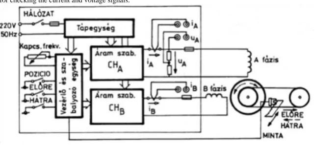
3. Details for the measurement
3.1. Main components of the drive
1. Hybrid stepping motor (type 23D-6209 A):
1. two phase stator windings: 4.7 A, 1.7V, 2. rotor with permanent magnet
3. stator/rotor tooth number: 48/50 4. full step angle: 1.8°,
5. at the end of the axis there is 1:36 reduction gearing with timing belt
![Figure 2. Rectified voltage Ua and input phase voltage/current Lit. [4]](https://thumb-eu.123doks.com/thumbv2/9dokorg/1123473.79096/8.892.114.600.176.446/figure-rectified-voltage-input-phase-voltage-current-lit.webp)

![Figure 5. Four Quadrant DC Drive with anti-parallel Converters [1]](https://thumb-eu.123doks.com/thumbv2/9dokorg/1123473.79096/10.892.109.750.285.578/figure-four-quadrant-drive-with-anti-parallel-converters.webp)