Available online at www.sciencedirect.com
Procedia CIRP 00 (2018) 000–000 www.elsevier.com/locate/procedia
8th CIRP Conference on High Performance Cutting (HPC 2018)
Hardware-in-the-loop experiment of turning
Akos Mikl´os ´
a,*, D´aniel Bachrathy
b, Rich´ard Wohlfart
b, D´enes Tak´acs
a, G´abor Porempovics
b, Andr´as T´oth
c, G´abor St´ep´an
a,baMTA-BME Research Group on Dynamics of Machines and Vehicles, N´ador u. 7, Budapest 1051, Hungary
bDepartment of Applied Mechanics, Budapest University of Technology and Economics, M˝uegyetem rkp. 5, Budapest 1111, Hungary
cDepartment of Manufacturing Science and Engineering, Budapest University of Technology and Economics, M˝uegyetem rkp. 3, Budapest 1111, Hungary
∗Corresponding author. Tel.:+36-1-463-1336; fax:+36-1-463-3471.E-mail address:miklosa@mm.bme.hu
Abstract
A hardware-in-the-loop (HIL) experimental setup is presented to analyze the stability of turning process. In our test rig, the dummy workpiece in the spindle can be excited in radial direction by an electromagnetic contactless actuator. This actuator is utilized to emulate the contact (cutting) force that acts originally between the tool and workpiece in case of a real process. In the HIL test, the displacement of the dummy workpiece is measured with the help of an optical sensor. A high performance real target computer is used to calculate the theoretical cutting force based on the present and past values of the relative displacements of the dummy workpiece. For the sake of simplicity, linear cutting force characteristics is implemented together with the emulated surface regeneration effect. In the HIL test, the loss of linear stability is detected for various real spindle speeds and virtual depth of cut, namely, the theoretically predicted pattern of the instability lobes is verified.
c
2018 The Authors. Published by Elsevier Ltd.
Peer-review under the responsibility of the International Scientific Committee of the 8th CIRP Conference on High Performance Cutting (HPC 2018).
Keywords: turning; hardware-in-the-loop; virtual machining, stability
1. Hardware-in-the-loop method in machining
Chatter vibration of machine tools presents a hard limita- tion in machining even nowadays although its physics was ex- plored already long time ago [1,2]. The stability charts with the lobe-structure of linearly stable and unstable parameter do- mains are well-known, however, experimental and theoretical investigation of the phenomenon is still an important topic for researchers [3]. Furthermore, chatter can damage not only the workpiece but also the tool or even the main spindle, hence, avoiding chatter is a basic task in machining. On the other hand, unsafe parameter ranges that are close to the linear stability lim- its are also used sometimes to enhance productivity, which in- creases the possibility of chatter vibrations. To detect the opti- mal parameter ranges, extensive experiments are required that are really time-consuming, expensive and still often unreliable.
Recent results have shown that beyond the traditional stable parameter domain of the machining process, there exist stable islands surrounded by unstable regions [4] in case of special tool geometries. To use these very efficient parameter domains, it is unavailable to cross unstable regions risking the damage of the machine tool. Thus, the experimental validation of these islands has not been carried out yet.
To detect the stable islands without causing any damage of
the machine tool, the monitoring of cutting forces can be an option. Namely, in case of unstable machining, the cutting forces and/or the maximum deformations of the tool or work- piece could be limited by the sudden interruption of the process.
Even though stability islands are in the moment rather in fo- cus of researchers, avoiding chatter vibrations is essential in the production, too. The same monitoring system would enable a safe environment for a straightforward determination of the op- timal chatter-free cutting conditions by tuning process parame- ters or by changing the tool or other elements of the process.
The practical realization of such a monitoring system would be a challenging task. To make tests in these risky parameter domains another option can be the replacement of the real tool- workpiece contact by a more controllable process. An actua- tor can be used, which can provide a properly controlled force that emulates the cutting force. Since only one component of the machining process is replaced, the behavior of the machine, the main spindle and the tool holder are unchanged, namely, a hardware-in-the-loop (HIL) experiment is constructed. By means of the full control over the cutting force, it is possible not only to save the test rig from damages but also to validate cutting force models, or to test new tool geometries and their capabilities virtually. A further promising application of the constructed test rig is its integration in CNC machines, since
2212-8271 c2018 The Authors. Published by Elsevier Ltd.
Peer-review under the responsibility of the International Scientific Committee of the 8th CIRP Conference on High Performance Cutting (HPC 2018).
2 A. Mikl´os et al.´ /Procedia CIRP 00 (2018) 000–000
it would enable a compact, fast and effective determination of machine dynamics to predict chatter conditions, or to simulate the machining virtually before the real process.
Of course, to keep the original dynamics of the machine tool and to maintain all the benefits of the HIL concept, a contact- less actuation of the cutting force is required. Rantatalo et al.
in [5] and Matsubara et al. in [6] solved this problem by using electromagnets as we also do it in our study. The electromag- netic force can be controlled by electronics, but the available maximum force and the efficiency of the actuator are affected by the generated eddy currents due to the rotation of the spindle [7]. In this study, we present a solution for this problem, too.
In the rest of the paper, a HIL experimental rig is presented in which one-directional measurement of the workpiece displace- ment and one-directional actuation are applied. The compo- nents of the rig, the contactless vibration measurement, the con- tactless actuation and the high-speed computation of the cutting force are shown. Experiments are carried out to prove the HIL concept.
2. Hardware-in-the-loop test environment
To realize the HIL experiment, the tool-workpiece contact has to be replaced by the emulated cutting force provided by an electromagnetic actuator (see Fig. 1). To produce the appropri-
Fig. 1. (a) real machining; (b) virtual machining; (c) HIL concept.
ate cutting force, we consider the most popular and generally applied relation for the nonlinear cutting force (see [1,8,9]):
F =kw1h0.75(rΩ)−0.1, (1)
where wis the chip width, h is the chip thickness, Ω is the spindle speed andkis a cutting coefficient of the process. Con- sidering that the variation ˜h of the chip thickness is small and the chip width is constant, furthermore, the effect of the varia- tion in the cutting velocityrΩcan be neglected because of the small exponent, the equation can be linearized [10] and written as
F =F0+k1h.˜ (2)
F0 is the constant part of the cutting force, andk1is the spe- cific cutting coefficient of the process which results from the linearization around the average chip thickness. Since the chip thickness depends on the actual position of the workpiece and on the position in one revolution earlier, the cutting force can be computed as
F =F0+k1(x(t)−x(t−τ)), (3) wherex(t) is the position of the workpiece at timet, andτis the time period of one revolution. Since we consider a linear
system and the average valueF0 of the cutting force has only influence on the vibrations through the nonlinearities of the sys- tem, we neglect the effect ofF0in our study.
If we want to calculate the force that is generated by the electromagnetic actuator, we need to measure the actual dis- placement of the rotating workpiece inxdirection, the actual angular positionϕ(t) of the workpiece, and we need to record the displacement of the workpiece in the previous turn. Then according to the calculated force, the electric current in the elec- tromagnet coil has to be set.
2.1. Spindle
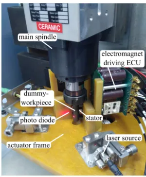
For the current experiment we used a 2 kW 3410 series Teknomotor three phase induction motor spindle with a max- imum spindle speed of 24 000 rpm. The spindle is equipped with hybrid angular bearings. The spindle is mounted in verti- cal position as it is shown in Fig. 2.
Fig. 2. Experimental setup.
The spindle speed is controlled by a variable frequency drive LS SV055iG5A-4 for which the reference signal is given through an analog input (0–10 V). Thus, the spindle speed can be set by an operator using a voltage source, or by a controller using any D/A converter having appropriate voltage range.
2.2. Contactless displacement measurement
The displacement of the dummy workpiece located in the spindle is measured precisely by a contactless laser-based sen- sor. Because of the definite wavelength of the laser the sensor is not sensitive to environmental light disturbances. In Fig. 3, the laser beam is grazing the cylindrical rotating part of the work- piece, and in case of even a tiny displacement of the workpiece, the intensity of the passing light changes at the other side. The use of a highly sensitive photo diode to measure the intensity results a very accurate displacement sensor.
The displacement sensor has superior static and dynamic performance. The sensor provides an analog output that is
A. Mikl´os et al.´ /Procedia CIRP 00 (2018) 000–000 3
Fig. 3. Laser beam sensor.
proportional to the displacement, with a measuring range of 0.2 mm and sensitivity of 48 mV/µm. The RMS noise at a band- width of 500 kHz is below 100 nm, which leads to sub-micron accuracy. The high resolution can be seen in Fig. 5, where raw data are provided. A rough calibration of the sensor can also be carried out knowing the runout of the tool, which is about 35µm for the current set-up
For the actual chip thickness, the angular position of the dummy tool has to be measured, too, which is done by a laser- based optical-reflective encoder. The encoder provides one square wave-like signal per revolution. The angular position is estimated by means of an observer taking only the rising edges of the encoder signal. Since there is no torque load on the main spindle, the spindle speed variation is very small to be estimated well by the time period of the previous rotation.
2.3. Contactless actuator
The force of the virtual cutting is produced by a contact- less electromagnetic actuator. Since the changes in the cutting force at high spindle speeds can be very fast, the force of the actuator has to be refreshed with high frequency, too. The con- trol rate was chosen for 100 kHz, thus for the spindle speed of 60 000 rpm we have at least 100 actuations for one turn. This allows us a precise reproduction of the cutting force, but it sets also high standards for the actuator. For very fast spindle speeds and for fast changing magnetic fields, eddy currents arise in ev- ery electrically conducting material. According to this we used only non-conducting materials close to the electromagnet. The frame of the actuator has been made of fiber reinforced PE com- posite, which also holds the laser sensors. The core of the elec- tromagnet is made from ferrite with relatively high saturation value (0.49 T). We also manufactured the dummy workpiece from the same ferrite material. The arrangement of the actuator is shown in Fig. 1 and 2.
The coil of the electromagnet has only low number of turns to keep the inductance of the electromagnet as low as possible, which requires high electric current to achieve reasonable mag- netic excitation and forces. The maximum force of the actuator is about 15 N in the present experiment [11], which is found to be enough to describe variational force component [10] at the initialization of the chatter vibration.
2.4. Cutting force calculation
As explained in the previous section, the sampling rate of the control has to be at least 100 kHz. The sampling of dis- placement and angular position encoder signals, the calcula- tions of the accurate angular position and the required force, and also the actuation have to be fit in this 10µs time frame.
We solved the task with a National Instruments PXIe-8881
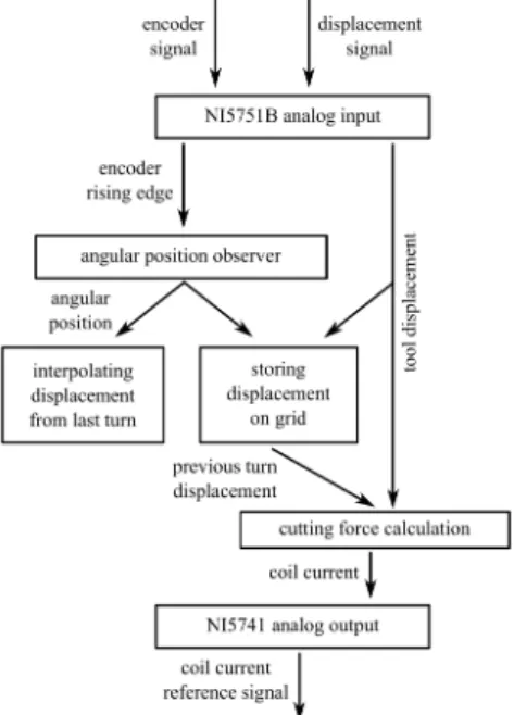
real-time-computer with two NI7976R FPGA modules. To the FPGA modules, an analog input card (NI5751B digitizer mod- ule with 50 MS/s sampling rate at 14 bit resolution) and an analog output card (NI5741 with 1 MS/s at 16 bit) have been connected. This system enables us to provide the required sam- pling rates, and accomplish the calculations in the given time frame. The algorithm of the calculation is shown in Fig. 4.
Fig. 4. Algorithm of the cutting force calculation.
The actual displacement of the rotating workpiece was mea- sured first by the laser sensor, and the signal level of the encoder was watched. If there was a rising edge in the encoder signal, the observer for the angular position started to measure the time period of the revolution. In the next rotation, constant spindle speed was assumed, and from the actual time elapsed after the last rising edge, the angular position could be estimated accu- rately. To have the displacements of the last turn, the displace- ments were stored in 256 angular positions, and between these points, the displacements were linearly interpolated. Thus, in each control cycle, the actual chip thickness could be calculated based on the difference of the actual and the prestored former displacements, and the required force could be computed with the help of Eqn. (3).
Even this fast control leads to an inevitable delay in the ex- periment, which could be critical in the measurement of regen- erative chatter vibrations. Analysis of the digitally sampled sys- tem has been carried out in [11,12], and the effect of different sampling frequencies on the stability has been investigated. The results showed that 100 kHz sampling frequency is appropriate, namely, the linear stability properties of the HIL experiment is very close to the properties of the original real system.
3. Proof-of-concept measurements
Stability charts of machining processes are typically con- structed in the plane of the chip width and the spindle speed.
In our study, we also analyse the effect of these parameters on the stability.
4 A. Mikl´os et al.´ /Procedia CIRP 00 (2018) 000–000
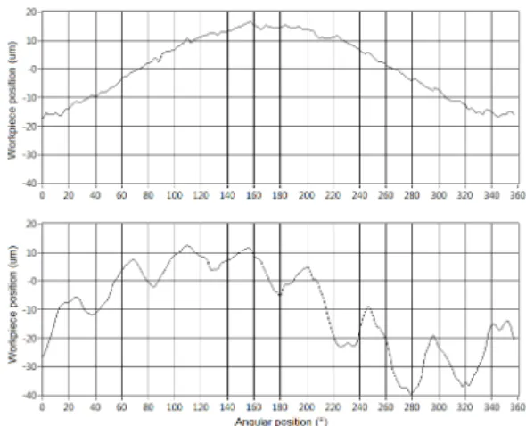
As we measure the displacement of the workpiece for dif- ferent angular positions, we can also identify the deviation of the workpiece from the ideal cylindrical shape. Since the sym- metry axis of the workpiece has some misalignment from the axis of rotation, a runout can be measured, which is seen in the top panel of Fig. 5. The runout has been measured to be 35µm peak-to-peak. A typical measured displacement of an unstable HIL simulation is shown in the bottom panel of Fig. 5, where the displacements of a workpiece can be seen. During the mea- surement, the cutting process was considered to be stable if the time history of the displacement was similar to the one in the upper panel and it was considered to be unstable when it was similar to the one in the lower panel.
Fig. 5. top: runout of the workpiece; bottom: regenerative vibration.
The measurement was carried out at a specific value of the cutting coefficientk1, and the spindle speed was varied between 20–200 Hz (1 200 – 12 000 rpm) with 5 Hz (300 rpm) steps.
In some cases, where the stability of the process could not be verified clearly, we considered the process to be on the limit of stability. The results of the measurements are shown in Fig. 6.
The dimensionless chip width is in linear relation withk1, how- ever the scale is not calibrated. According to the lobe-structure, the stable and unstable regions alternate along the horizontal axis, and the width of the stable intervals are increasing with increasing spindle speeds. The vibration frequency in each un- stable point was about 620 Hz, slightly above the first natural frequency of the main spindle (fn =600 Hz).
In the lower spindle speed domain, a large stable region can be observed. This is due to the fact that only 256 angular posi- tions are differentiated in one turn in our measurement, and in the low spindle speed domain, the chatter vibration is not sam- pled appropriately. Namely, the frequency of the vibration is larger then our sampling rate. Similar effect can be observed when stability charts are calculated by the semi-discretization method with insufficient number of discretization points [13].
4. Conclusion
In the present paper we showed a hardware-in-the-loop ex- perimental rig that is able to emulate cutting processes. First, the concept of the semi-virtual machining was shown, then the components of the test rig were presented. Numerous mea- surements were carried out for different spindle speeds, and the measurements showed good qualitative agreement with the an-
Fig. 6. Stable and unstable virtual machining.
alytical stability charts. The results proved the HIL concept for machining.
With the test rig, it is possible to investigate the stability of cutting processes even in the unstable regions without the risk of damage in the system. Furthermore, it is possible to validate cutting force models or to test the dynamic properties of cutting tools with specially designed tool geometries semi-virtually.
Acknowledgements
The research leading to these results has received fund- ing from the European Research Council under the European Unions Seventh Framework Programme (FP/2007-2013)/ERC Advanced Grant Agreement n. 340889.
References
[1] Tlusty, J., Spacek, L.. Self-excited vibrations on machine tools. Prague, Czech Republic: Nakl CSAV. [In Czech.]; 1954.
[2] Tobias, S.A.. Machine Tool Vibration. Blackie and Son, Ltd., London;
1965.
[3] Munoa, J., Beudaert, X., Dombovari, Z., Altintas, Y., Budak, E., Brecher, C., et al. Chatter suppression techniques in metal cutting. CIRP Annals 2016;65(2):785–808.
[4] Munoa, J., Zatarain, M., Dombovari, Z., Yang, Y.. Effect of mode interaction on stability of milling processes. In: 12th CIRP Conference on Modelling of Machining Operations, San Sebastian, Spain. 2009, p. 927–
933.
[5] Rantatalo, M., Aidanp¨a¨a, J.O., G¨oransson, B., Norman, P.. Milling machine spindle analysis using fem and non-contact spindle excitation and response measurement. International Journal of Machine Tools and Manu- facture 2007;47(7):1034 – 1045.
[6] Matsubara, A., Tsujimoto, S., Kono, D.. Evaluation of dynamic stiff- ness of machine tool spindle by non-contact excitation tests. CIRP Annals 2015;64(1):365–368.
[7] Yamazaki, T., Matsubara, A., Fujita, T., Muraki, T., Asano, K., Kawashima, K.. Measurement of spindle rigidity by using a magnet loader. Journal of Advanced Mechanical Design, Systems, and Manufac- turing 2010;4(5):985–994.
[8] Taylor, F.W.. On the art of cutting metals. On the Art of Cutting Metals, ASME 1907;28.
[9] Kienzle, O., Victor, H.. Spezifische schnittkr¨afte bei der metallbear- beitung. Werkstattstechnik und Maschinenbau 1957;47(5):224–225.
[10] Stepan, G.. Retarded Dynamical Systems. Longman, Harlow; 1989.
[11] Mikl´os, ´A., Tak´acs, D., Wohlfart, R., Porempovics, G., Moln´ar, T.G., Bachrathy, D., et al. The development of high speed virtual milling test.
In: ASME 2017 Dynamic Systems and Control Conference; vol. 2. 2017, p. V002T16A003.
[12] Veraszto, Z., Stepan, G.. Nonlinear dynamics of hardware- in-the-loop experiments on stickslip phenomena. Interna- tional Journal of Non-Linear Mechanics 2017;94:380 – 391.
doi:https://doi.org/10.1016/j.ijnonlinmec.2017.01.006.
[13] Insperger, T., St´ep´an, G.. Semi-Discretization for Time-Delay Systems:
Stability and Engineering Applications. Applied Mathematical Sciences;
Springer New York; 2011.