Available online at www.sciencedirect.com
Procedia CIRP 00 (2018) 000–000 www.elsevier.com/locate/procedia
8th CIRP Conference on High Performance Cutting (HPC 2018)
Stability of turning process with tool subjected to compression
Bence Beri*
a, Gabor Stepan
aaBudapest University of Technology and Economics, Department of Applied Mechanics, M˝uegyetem rkp. 5, Budapest 1111, Hungary
∗Corresponding author. E-mail address:beri@mm.bme.hu
Abstract
This study investigates how the stability of the turning process changes when the tangential component of the cutting force is also taken into account as a compressive force acting on the cutting tool. The tool is modelled by a cantilever beam; the mathematical model is based on the Euler-Bernoulli beam theory. The effect of compression appears through the lateral stiffness of the tool. Two cases are separated in connection with the compressive force: constant and varying forces. Since compression reduces the natural frequency of the cutting tool, this also affects the stable region of the turning operation.
c
2018 The Authors. Published by Elsevier Ltd.
Peer-review under the responsibility of the International Scientific Committee of the 8th CIRP Conference on High Performance Cutting (HPC 2018).
Keywords: turning process; regenerative effect; stability; compression
1. Motivation
During machining processes, unexpected vibrations called chatter might occur due to the regenerative effect, which gener- ally results in noise or tool break and affects the quality of the machined surface. This is because either the cutting tool or the workpiece or both are flexible and the chip thickness varies due to the relative vibrations of the tool and the workpiece.
In case of turning, the regenerative effect is modelled by a time delayed system. The general mechanical model was con- structed by Tobias [1] and Tlusty [2]. The tool cuts the surface
Nomenclature cy modal damping h0 intended chip thickness h instantaneous chip thickness IE bending stiffness of the cutting tool ky modal stiffness
Kx,y cutting-force parameters L length of the cutting tool m modal mass
w chip width τ time delay ζ damping ratio
ωn natural angular frequency Ω spindle speed
that was machined in the previous cut, and the chip thickness is
described by the current and the previous position of the tool.
The time delay between two succeeding cuts is equal to the period of the workpiece rotation.
The objective of this study is to take into account the possi- ble appearance of compressive effect on the cutting tool, which somewhat modifies the natural frequency of the bending vibra- tion of the tool. There have been related results in the literature:
Budak et al. [3] and Stepan et al. [4] have investigated how the workpiece dynamics changes due to mass removal and the variation of the tool position in turning. Bayly et al. [5] dealt with low frequency vibration in drilling to find agreement with drilling tests in the presence of large longitudinal cutting forces.
Roukema and Altintas [6] and Heisig and Neubert [7] consid- ered lateral vibration of drilling tools under compression. Beri et al. [8,9] have examined how the lateral stiffness of a can- tilever beam changes under compression, tension and torsion, respectively.
In case of turning, there exist certain tool-workpiece ar- rangements where the tangential component of the cutting force acts on the cutting tool as a compressive force, which modifies the natural frequency of the system. The tool is modelled by a cantilever beam that is considered to be prismatic, homoge- neous, linearly elastic and inextensible. Its mathematical model is based on the Euler-Bernoulli beam theory and the effect of compression appears through the lateral stiffness of the tool. To provide a wider picture about the influence of compression on the stability of the turning process, two cases are investigated:
constant and varying forces. The latter case is in connection with the regenerative effect. Since compression decreases the
2212-8271 c2018 The Authors. Published by Elsevier Ltd.
Peer-review under the responsibility of the International Scientific Committee of the 8th CIRP Conference on High Performance Cutting (HPC 2018).
2 Author name/Procedia CIRP 00 (2018) 000–000
x y z Tool
Workpiece
Feed
𝛺
w m cy ky
h(t) h0
F y(t-𝜏)
y(t) x
y
Tool
Feed
Present cut Previous cut
(a) (b)
x
Fy R
𝛺R
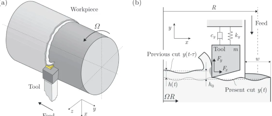
Figure 1. (a) Tool-workpiece arrangement where the tangential component of the cutting force acts on the tool as compression. (b) Mechanical model of surface regeneration in turning operation.
lateral stiffness and modifies the bending natural frequency of the cutting tool, it has a destabilizing effect, that is, it reduces the stable region of the turning process. To support our numeri- cal results, some analytical formulas are also presented on how the lobe structure will change by the variation of the compres- sive component of the cutting force.
2. Modelling and Analysis
In order to perform the stability calculation, the mechanical model of the turning operation of a flexible cutting tool is con- sidered as shown in Fig.1. The governing equation of the 1 DoF model assumes the form
¨
y(t)+2ζωny(t)˙ +ω2ny(t)= Fy(t)
m , (1)
whereζ =cy/(2mωn) andωn = p
ky/m. Here,ky =ky(Fx) is the lateral stiffness of the cutting tool in theydirection depend- ing on the tangential component of the cutting forceFx, which acts as a compressive force. Based on the Euler-Bernoulli beam theory, the stiffnesskyof the clamped tool under compression Fxis expressed by [8] in the form
ky= α3IE
tan(αL)−αL (2)
whereα= √
Fx/IE. Equation (2) can be approximated by the power series
ky= 3IE L3 − 6
5LFx− O(F2x), (3) where only the first two components are considered since even the Euler buckling loadFcr = π2IE/(4L2) is satisfactorily ap- proximated byky=0.
In Eq. (1), the widely used cutting force characteristic [1] is applied:
Fx(t)=Kxwhq(t), (4)
Fy(t)=Kywhq(t), (5)
whereqis the cutting force exponent, which represents a strong nonlineraity and plays significant role in determining the chatter
free cutting conditions. In the literature, there exist many sug- gestions for the value of exponentq(see [10–16]) to provide an accurate estimation for the cutting force characteristics.
In the mechanical model depicted in Fig.1.(b), it is assumed that the tool does not leave the surface, that is, the instantaneous chip thicknessh(t) >0 during the turning operation. The chip thickness
h(t)=h0+y(t−τ)−y(t) (6) can be obtained by taking into account the regenerative effect, that is, the cutting tool meets the surface that was formed in the previous cut (see Fig.1(b).) Here,τis the regenerative time delay that is approximated by
τ=60
Ω (7)
where the constant spindle speedΩis given in (rpm).
2.1. Type of Compression
In connection with the compressive force Fx, two cases are separated: constant and varying forces. In the first case,Fxis considered to be constant, thus it affects only the lateral stiff- ness of the cutting tool by a constant value through Eq. (3). In the latter case, let us consider that the tangential force Fx is proportional to the normal forceFy:
Fx(t)= Fy(t)
σ (8)
whereσ=0.3 is a typical value in the literature (see for exam- ple [18]). Substitution of Eqs. (5) and (6) into (8) yields Fx(t)= Kyw
σ (h0+y(t−τ)−y(t))q (9) whereFxis proportional to the chip widthwand the regenera- tive effect also appears. We note that the expansion of the lateral stiffness (see Eq. (3)) gives
ky=ky0−ky1
σ Kyw(h0+y(t−τ)−y(t))q, (10) whereky0 =3IE/L3andky1 =6/(5L). By means of Eqs. (1), (5) and (6), the equation of motion of the system can be written in the form
¨
y(t)+2ζωny(t)˙ +ω2ny(t)= Kyw
m (h0+y(t−τ)−y(t))q. (11)
Author name/Procedia CIRP 00 (2018) 000–000 3
0.0 0.2 0.4 0.6 0.8 1.0 1.2 1.4
𝜔→𝜔n 𝜔→∞
j=1 j=2
𝜁=0.05 1
0.2 2 0.0 0.4 0.6 0.8 1.0
𝛺/(60f )
w
n0
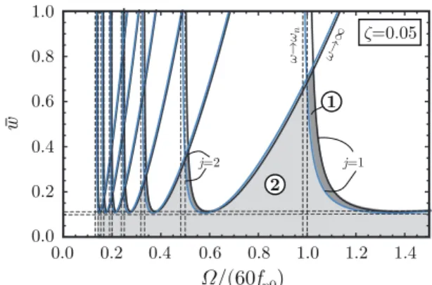
Figure 2. Dimensionless stability diagram where notation¬shows the stable region of the system subjected to no compression and notationshows the stable region of the system subjected to large constant compression (Fx=8000 N). The damping ratio isζ =0.05 and the length of the tool isL=0.10 m.
Here,fn0=ωn0/(2π) is thebasicnatural frequency.
By considering the equilibrium positiony(t) =y0in Eq. (11), one obtains
y0 = Kywhq0 ky0−kσy1Kywhq0
. (12)
This constant steady-state corresponds to the deflection of the tool when no vibrations occur during the operation, that is, it means the stationary case. The linearisation about the equilib- rium position gives the variational system [18]
η(t)¨ +2ζωnη(t)˙ +(ω2n+H)η(t)=H(η(t−τ)−η(t)), (13) whereη means the small perturbation about the equilibrium.
Here,ω2n =(ky0−ky1Kywhq0/σ)/mand the specific cutting co- efficientH=Kywqhq−10 (1+ky1y0/σ)/m.
The stability analysis of the system Eq. (13) is performed by the D-subdivision method [17], which gives two formulas H=(ω2−ω2n)2+4ζ2ω2nω2
2(ω2−ω2n) (14)
and
Ω = 30ω
jπ−arctanω2−ω2n 2ζωωn
, j∈N0 (15) whereωis the frequency of the arising regenerative vibrations.
These two expressions provide parametric stability boundary curves, called D-curves, that represents dynamic loss of stabil- ity (Hopf-bifurcation).
3. Results
When the tangential forceFxis either constant or zero, the natural angular frequency ωn is also constant in accordance with Eq. (3) andHis simply equal to ¯H=Kywqhq−10 /min Eq.
(13) (see in Ref.[18]). In the stability charts, the dimensionless chip width ¯w = H/ω¯ 2n0 is used whereωn0 = p
ky0/mdenotes thebasicnatural angular frequency.
The dimensionless D-curves can be constructed by using the analytical expressions Eqs. (14) and (15) shown in Fig.2. w¯ is proportional to the chip widthw, thus only the practically relevant domain ¯w > 0 is depicted. The vertical dotted lines
0.0 0.2 0.4 0.6 0.8 1.0 1.2 1.4
𝜔→∞
𝜔→
n𝜔
j=1 j=2
𝜁=0.05
0.0 0.5 1.0 1.5 2.0 2.5 3.0 3.5
w
𝛺/(60f )n0
wcr
Figure 3. Dimensionless stability diagram of the system subjected to varying compression. The numerical valuesσ=0.3, ζ=0.05,q=0.6,h0=0.005 m andL=0.1 m are used. Here,fn0=ωn0/(2π) is thebasicnatural frequency.
(see Fig.2) are asymptotes, which can be obtained from Eqs.
(3) and (15) Ω0asy= lim
ω→ωnΩ = 1 j
60 2π
rky0−ky1Fx
m . (16)
The horizontal dotted lines describe the minimum points of the lobes where the turning process is still stable independently to the cutting speed. These are determined by Eq. (14) using the method of local minima. It can be seen that the constant com- pressive force provides a shifted stability map. The map moves left and down because the lateral stiffness of the cutting tool decreases, which affects the natural angular frequency, too. Ac- cordingly, even a large constant compression force has negligi- ble destabilizing effect.
In contrast, in case of varying compression (see Subsec.2.1.), Hand the natural angular frequencyωnalso depend on the chip width w, which leads us to a nonlinear expression in w (see Eq.(14)). Hence, we are only able to provide the D-curves nu- merically. The dimensionless stability map can be seen in Fig.3.
Similarly to Eq. (16), the asymptotes can easily be calculated.
Since the natural angular frequency is a function of the chip widthw, the asymptotes will also depend onwdescribed by the closed form analytical formula
Ωvasy= 1 j
60 2π
s
ky0−kσy1Kywhq0
m . (17)
Since the natural angular frequency decreases as ¯wincreases (see in Fig.3), the asymptotes are bent to the left. There is a critical value where both the asymptotes and the D-curves meet, which can be expressed by
¯
wcr= 5Lσq 6h0
. (18)
This value means the static loss of stability of the cutting tool, that is, the lateral stiffness of the tool decreases to zero, which results in the buckling of the tool and tool breakage.
In Fig.4., the stability diagrams of the varying and the zero compression cases are merged for different damping ratio val- ues. The lobe structure is shifted down and deflected both to the left and also somewhat to the right compared to the non- compressed case. Basically, the varying compressive force has a large scale destabilizing effect but it might also broaden the reference (non-compressed) stable region slightly at relatively
4 Author name/Procedia CIRP 00 (2018) 000–000
0.0 0.2 0.4 0.6 0.8 1.0 1.2 1.4
𝜔→∞
𝜔→∞
𝜔→𝜔n
𝜔→𝜔
n
j=2 j=1
𝜁=0.01
0.2 2 0.0 0.4 0.6 0.8 1.0
(a)
0.0 0.2 0.4 0.6 0.8 1.0 1.2 1.4
𝜔→∞
𝜔→𝜔n 𝜔→∞
𝜔→
𝜔n
j=2 j=1
0.2 2 0.0 0.4 0.6 0.8 1.0
(b)
0.0 0.2 0.4 0.6 0.8 1.0 1.2 1.4
𝜔→∞
𝜔→∞
𝜔→𝜔n
𝜔→𝜔
n
j=2 j=1
1 0.2 2
0.0 0.4 0.6 0.8 1.0
(c)
Stable
1
𝛺/(60f )n0
𝛺/(60f )n0
𝛺/(60f )n0 www
𝜁=0.10 1
𝜁=0.05
Figure 4. Dimensionless stability charts where notation¬shows the sta- ble region of non-compressed system and notation shows the stable re- gions of the system subjected to varying compression. The numerical values σ=0.3,q=0.6,h0=0.005 m andL=0.1 m are used. Here,fn0=ωn0/(2π) is thebasicnatural frequency.
small damping ratios as shown in the enlarged panel of Fig.4 (a). As the damping ratio grows, the stable region significantly reduces in contrast to the reference case. This means, for exam- ple, that the available maximum values of the chip widthware reduced in the stable pockets of the charts.
4. Conclusion
The paper brings up the classical topic of the stability of the turning operation, which can be described by a 1 DoF dynami- cal model. The cutting force can be resolved to a normal force Fyand a tangential forceFxthat acts on the cutter as compres- sion in certain tool-workpiece configurations. This study inves- tigated two cases: constant and varying compressive forces.
Based on the Euler-Bernoulli beam theory, the lateral stiff- ness of the cutting tool can be calculated, which also describes the variation of the natural angular frequency of the tool. By us- ing constant compression, the lobe structure is slightly shifted
to the left and down compared to the non-compressed case.
In contrast, under the effect of the varying compression, the stability map is shifted down and deflected both to the left and to the right compared to the non-compressed case. This predicts a non-negligible reduction of the size of the stable pockets, which serves as a basis for future experimental verification. These phenomena may become relevant when slender tools are used for turning inside lengthy tubes.
Acknowledgements
The research leading to these results has received fund- ing from the European Research Council under the European Unions Seventh Framework Program (FP/2007-2013)/ERC Ad- vanced Grant Agreement No. 340889.
References
[1] Tobias SA. Machine tool vibration. Blackie, London (1965).
[2] Tlusty J, Polacek M. The stability of machine tools against self-excited vibrations in machining. International Research in Production Engineering, ASME, 1963; Vol. 1:465-474.
[3] Budak E, Tunc LT, Alan S, ¨Ozg¨uven HN. Prediction of workpiece dynam- ics and its effects on chatter stability in milling. CIRP Annals - Manufac- turing Technology. 2012; 61(1). p. 339-342.
[4] Stepan G, Kiss AK, Ghalamchi B, Sopanen J, Bachrathy D. Chatter avoid- ance in cutting highly flexible workpieces. CIRP Annals - Manufacturing Technology. 2017; 66(1). p. 377-380.
[5] Bayly P, Lamar M, Calvert S. Low-Frequency Regenerative Vibration and the Formation of Lobed Holes in Drilling. ASME J. Manuf. Sci. Eng. 2002;
124(2), p. 275-285.
[6] Roukema J, Altintas Y. Generalized Modeling of Drilling Vibrations-Part II: Chatter Stability in Frequency Domain. Int. J. Mach. Tools Manuf. 2007;
47(9), p. 1474-1485.
[7] Heisig G, Neubert M. Lateral Drillstring Vibrations in Extended- Reach Wells. IADC/SPE Drilling Conference. 2000; New Orleans, LA, Feb.
2325, SPE Paper No. SPE-59235-MS.
[8] Beri B, Stepan G, Hogan SJ. Effect of Potential Energy Variation on the Natural Frequency of an Euler-Bernoulli Cantilever Beam Under Lat- eral Force and Compression. Journal of Applied Mechanics. 2017; 84(5).
051002.
[9] Beri B, Hogan SJ, Stepan G. Structural stability of a light rotating beam under combined loads. Acta Mechanica. 2017; 228(7). p. 3735-3740.
[10] Stepan G, Dombovari Z, Munoa J. Identification of cutting force character- istics based on chatter experiments. CIRP Annals - Manufacturing Tech- nology. 2011; 60(1). p. 113-116.
[11] Shi HM, Tobias SA. Theory of Finite Amplitude Machine Tool Instabil- ity. International Journal of Machine Tools Design and Research. 1984;
24:4569.
[12] Endres WJ, Loo M. Modeling Cutting Process Nonlinearity for Stability Analysis-Application to Tooling Selection for Valve-Seat Machining. Proc.
5th CIRP Workshop, USA, West Lafayette. 2002.
[13] Taylor FW. On the Art of Cutting Metals. Transactions of the American Society of Mechanical Engineers. 1907; 28:31350.
[14] Kienzle O. Spezifische schnittkrafte bei der metallbearbeitung. Werk- stattstechnik und Maschinenbau. 1957; 47:224225.
[15] Armarego EJA, Deshpande NP. Computerized Predictive Cutting Models for Forces in End Milling including Eccentricity Effect. Annals of CIRP.
1989; 38(1):4549.
[16] Altintas Y. Manufacturing Automation. UK, University Press Cambridge.
2012.
[17] Stepan G. Retarded Dynamical Systems: Stability & Characteristic Func- tions. Longman Scientific & Technical. USA, New York. 1989.
[18] Insperger T, Stepan G. Semi-Discretization for Time-Delay Systems.
Springer-Verlag, New York. 2011.