Distillation
R. S. SILVER
L General S y s t e m Engineering of Distillation Plant A . T h e Distillation Process
B. System Engineering
77 77 81 87 87 92 102 1 1 0 II. Internal System Engineering of Distillation Plant
A . Single-Effect Distillation B. Multiple-Effect Distillation C. Multistage Flash Distillation D. T h e Vapor-Compression Process Acknowledgments
List of S y m b o l s Units
1 1 4 1 1 4 115
I. General System Engineering of Distillation Plant
A . T H E DISTILLATION PROCESS
7. Products of the Process
By distillation we mean a process in which a portion of a liquid is first evaporated and subsequently condensed. In this definition the word and is all-important. The end product of distillation is in the same phase as it was initially, i.e., in the liquid phase. Hence distillation implies that at least the latent heat of evaporation be first supplied to the substance and then at least its latent heat of condensation be extracted from it. Clearly, this process is pointless for a pure liquid, as we should have no different substance at the end than at the beginning. The process is of use therefore only when the original liquid is a mixture of substances one of which may be evaporated at given conditions of temperature and pressure in greater proportion than the others. Hence by distillation we achieve an end product in which the more volatile
77
78 R. S . SILVER
substance preponderates as compared with the original liquid. In the particular case of distillation of sea water, we assume that the salts in solution are, at least in the range of temperatures and pressures within which we work, completely nonvolatile. Thus, in principle, we evaporate pure H20 alone as vapor and, by condensing this, get pure H20 liquid as an end product.
This, however, is not the only product. If we have supplied sea water at a rate Mf and produce distillate at rate Md , we also have a rate Mj — Md of other material rejected from our system. If the original concentration of all salts in the sea water is represented by Cf, the original rate of total salts fed to the plant is CfMf, so that the amount of H20 substance in the feed is Mf(\ — Cf). Hence the amount of H20 substance in the reject stream is Mf(l — Cf) — Md . The concentration of salts in this reject stream is now CfMfj{Mf — Md). The ratio of feed to distillate produced is MfjMd , which is usually called the feed ratio xf. The concentration factor xc is defined as xfj{xf — 1) and is the factor by which the initial sea-water salt concentration is multiplied to give the concentration of salts in the reject stream. This reject stream is called the brine, and the quantity Mf — Md may be denoted by Mb . Depending on the arrangements within the plant, the liquid being processed may vary in concentration at different sites in the plant but will in general be somewhere between Cf and xcCf.
2. Energy Requirements
In an idealized process, the feed, the distillate, and the brine would all be at the same temperature, and the only enthalpy difference between products and feed would be represented by the effective heat of solution λ.1 For the range of concentrations normally used, this is of the order of 1.2Btu/lb of distillate produced. Hence there must be at least an input energy of this amount, and λ is the absolute minimum energy cost which could be postulated (not realized) for the desalination of sea water by any process.
In practice, again by any process, more energy must be consumed, and this energy either must appear in the end temperature of the distillate and/or brine, or must be rejected by some other energy-
1 This is defined as product enthalpy + brine enthalpy — feed enthalpy. Since the energy requirements for distillation processes (except vapor-compression distillation) are primarily thermal rather than mechanical or electrical, it is convenient to introduce this subject in terms of enthalpy rather than free energy or exergy balances. A discussion of the energetics of vapor-compression distillation in terms of exergy balances is found in Chapter 2.
rejection device somewhere in the plant. In general, the energy balance includes such additional rejection as well as the temperature excess of brine and distillate above feed. For example, if we boil sea water in the crudest possible distillation system, we shall need to supply a latent heat of at least Lf to convert each pound of water substance into vapor, and shall then need to extract Ld to condense that vapor into liquid water.
The difference Lf — Ld , the latent heat of evaporation from the solution less the latent heat of condensation of the pure water, is in fact λ. But to condense the vapor to the desired product we have to use a cooling stream to extract Ld , which must necessarily be rejected. Hence the total rejection per pound of distillate is Ld in the auxiliary stream. If, for simplicity, the distillate and brine products are at present assumed to be at the same temperature as the feed, then λ is the enthalpy difference of the products above the feed. Thus the total efflux enthalpy is Ld + λ, giving a total Lf, which is necessarily equal to the energy supplied.
Now in certain complex forms of the distillation process, which we shall discuss in detail later, it is possible effectively to use a substantial part of the latent heat Ld given out in condensing as a contribution to the latent heat Lf required for evaporation. Such use, which is generally called ''regenerative/' means that the actual energy supplied per pound of distillate product can be much less than Lf. Let it be denoted by Lfjr. Again under the assumption that the end products are at the same temperature as the feed, λ is the only enthalpy difference of the products.
Hence there must be an auxiliary rejection loop or cooling stream as before, but this time rejecting (Lf/r) — λ, so that the total outlet energy will balance the total input Lf/r .
In a finite-size distillation plant, it is of course impossible to have the brine and distillate products brought back to the sea-feed temperature (except in the unlikely event that the air temperature was consistently below the sea temperature so that air could be used as a coolant). Hence we must in general write sb(tb — tf) and sd(td — tf) for the enthalpy contents of reject brine and distillate, respectively, in addition to λ. Thus if the auxiliary cooling loop rejects qa of heat per pound of distillate made, we have the energy balance for this system as
= Mdqa + MdX + Mbsb(tb ~ tf) + Mdsd(td ~ tf). (3.1) Therefore,
h r But
= ?„ + λ + sd(td - tf) + ^ sb(tb - t,).
Mf-Md
= xf — 1.
80 R. S . SILVER
Hence
r = hi (2 2)
qn+ λ + sd(td - tf) + (Xf - \)sb(tb -tf) K ' } or
qa = y - λ - sd(td - tf) - (xf - \)sb(tb - tf). (3.3) It is customary to refer to a characteristic R, called the performance ratio of the plant. This is defined precisely as the number of pounds of distillate produced per 1 0 0 0 Btu of heat input. Hence we have
R =U] 0 0 0 M« . (3.4)
heat input
Earlier we defined Lfjr as the heat input per pound of distillate pro
duced. Hence
R = (1000/L^r. (3.5) Since L1 is of the order of 1 0 0 0 Btu/lb, R and r have the same order of
magnitude, and each is an approximate measure of the other. Moreover since r is defined from the relation
Heat input per pound of distillate product = Lfjry
it represents the number of pounds of distillate obtained from a heat input oiLf, i.e., from the latent heat of evaporation of 1 lb of vapor from sea water. Thus r is conventionally named the gained output ratio of the plant.
It will be noted that, since sea water throughout the world is at temperatures such that even the latent heat of evaporation from pure water exceeds 1 0 0 0 Btu/lb, Lf is always greater than 1 0 0 0 ; therefore, R is always less than r.
In practice, some confusion exists among different manufacturers, who quote performance ratios or gained output ratios quite indiscrim
inately when referring to plant specifications.
The importance of either R or r is that this is the plant designer's starting point. T h e system designer, having examined the over-all economic design, will have arrived at an optimum energy consumption, which defines R*y the optimum performance ratio. T h e plant designer must design a plant which will obtain /?*, and therefore an implied r*
also. Whatever else he does in the course of his design, his plant must contain an element which will reject the correct qa when r* is substituted for r in Eq. (3.3). There is of course, as we shall see in detail later, a
feedback interaction between the plant design and the economic design.
In general, the plant will have a higher capital cost as R is increased, and the optimum is defined when the incremental benefit of reduced energy cost by increasing R is just offset by the inevitable increase in capital cost.
Ingenious plant design may modify i ? * by modifying design so that the rate of increase of capital cost with R is less than before: thus a higher /?*
can be aimed at.
B. SYSTEM ENGINEERING
L Simple Plants for Distillation Only
W e may now continue and clarify the matter of over-all energy balance by reference to Fig. 3.1. In this diagram the solid-line box
Gross heat input Auxiliary rejection
loop rejecting Qa
\ Distillate product
F I G . 3 . 1 . Simple arrangement of energy supply to a distillation plant.
represents the distillation plant proper. The total auxiliary rejection Qa
shown is Mdqa . Now in any plant, some pumping power is needed to keep material moving. Hence the total energy is not only the thermal amount Η shown in the diagram but also the mechanical amount Ρ indicated. Since, ultimately, Ρ is entirely absorbed by dissipation some
where in the circuit (assuming all products and auxiliary cooling arrangements ultimately at the same horizontal ground level and back to atmospheric pressure and negligible kinetic effects), then it is the sum (H -f P) which must exactly supply Lf/r. For many design reference purposes, however, and since Ρ is usually small compared with H, some manufacturers and designers quote values of R or r from a basis which includes Η only. Again this practice is a source of confusion in making comparisons.
However, another important difference is revealed when we consider the dashed line in Fig. 3.1. T o produce P, an engine must in general be
82 R. S . SILVER
employed, requiring a heat input He separate from that of the distillation plant. W e have therefore a gross heat consumption QT = Η + He. T h e true specific energy consumption of such an installation is therefore given by QT/Md = qT. Now
Md(Lflr) = H + P = H + H.-Q„=QT-Q„.
Hence
1000M,
1 0 0 0 , (3.7)
- Ver
or
1 0 0 0 . η «λ
0r = + qer · (3.8) In these equations qer is the engine reject heat brought to a base of
unit weight of distillate product. It arises from the energy balance across the dashed line, the first term of Eq. (3.8) being the energy flux across the internal solid-lined box.
Now it should be obvious that the important figure in determining the proper fuel economy of an installation is really qT, and not R, which refers only to the distillation plant portion. Yet this fact is too often not recognized and such failure can give rise to anomalies. T h e situation arises from the need to have pumping power and the need to have a rejection heat Qer from any heat engine producing power P.
Good system engineering design can use this fact to advantage, which can be seen by comparing Fig. 3.2 with Fig. 3 . 1 . In this a portion ocQer
of the total engine reject Qer is taken and used to supply some of the
Grossheot input
Or
H-aOer Heot input α α
Heat input He
Engine
Η
Power input
Engine reject heat (\-a)Qe,
Auxiliary rejection loop rejecting Qa
""Ι
I Sea-water feed
Mf at tf
1-
I
I Distillate product
! at tH
Brine reject
Mb at tb
F I G . 3.2. Part of reject heat from engine used to s u p p l e m e n t the heat i n p u t to the distillation plant.
heat input ˙ to the distillation plant. (It is essential for this purpose that ocQer be available at a temperature in excess of the temperature at which ˙ is absorbed in the distillation plant.) Analysis soon shows that we now have, instead of Eq. (3.8),
9τ = 1-ψ + (1~ oc)qcr . (3.9) The best arrangement occurs when α = 1, and then
qT = 1000/fl (3.9a)
and R does give immediately an indication of the specific fuel con
sumption.
2. Combined Distillation and Power Plants
Another situation of great practical importance is indicated by Fig. 3.3.
Here the engine is larger than required to produce only P, but produces an additional power Ps, which can be sold for external purposes. This means a higher rejection quantity for Qer, and so a.Qer can be higher.
If sufficient power can be sold, ocQer is equal to ˙ and we get the situation shown in Fig. 3.4.
In Figs. 3.3 and 3.4 the energy balance across the dashed lines is relevant not only to distillation but to the joint production of water and power for sale. W e want to limit our discussion to the water plant.
How are we going to establish a relation between qT and R for situations of the type of Figs. 3.3 or 3.4, where Ps is not zero ? T h e consumption of the distillation plant remains at 1000/P; and we are supplying it in full, but taking less heat along the line ˙ aQer in Fig. 3.3 and zero in Fig. 3.4.
Gross heot input
H-aQmt Heat input
Heat input
aOer Engine
Power) input
Engine reject heat [\-a)0mr
Output power for sale
Auxiliary rejection loop rejecting Qa
Seo-water feed Mf ot / / Distillate product
I Brine reject Mb ot tb
F I G . 3.3. S i m p l e plant with engine producing excess p o w e r w h i c h can be sold.
R. S. SILVER
Gross heot input
Meat input H9
Heat input
Engine
˙ Power input
Engine reject]
heat
\\-a)Q
Output power for sale
Auxiliary rejection loop rejecting Qa
'Seo-woter feed
\Mf at tf Distillate product I Md ot td
Brine reject Η at th
aOer= ˙ QT-He
F I G . 3.4. Combined distillation and power plant with heat input to distillation plant supplied solely from engine reject heat.
In fact, we have to invoke another circumstance to establish an acceptable relation.
The system of Figs. 3.3 and 3.4 is based upon having a market for Ps
which would have had to be satisfied in any case. If uncombined with a distillation plant we should normally have made the thermodynamic conversion of the engine as high as possible by rejection of all Qer at the lowest possible temperature governed by ambient conditions. Let this be ter . If we have chosen for distillation purposes to reject the portion
aQer at a higher temperature t'er, we have lost some thermodynamic efficiency. Let the maximum engine temperature be Ts . Then the maximum amounts of work available from one unit of heat input would be numerically equal to (Ts — ter)/Ts for rejection at ter, and (Ts — t'er)/Ts
for rejection at t'er. Thus rejection of ter/Ts at ter and t'er/T8 at t'er would give these respective amounts of work per unit of heat supplied. Thus to obtain one unit of work, we can either supply TJ( Ts — ter) units of heat at Ts and reject ter/(Ts — ter) units at ter , or TS/(TS — t'er) units at Ts
and reject t'er/(Ts — t'er) units at t'er . Thus if we reject at t'er, we need to supply TS/(T8 — t'er) — TJ(TS — ter) units more for obtaining one unit of power.
This increase enables us to reject t'erj{Ts — t'er) units at our suitable temperature t'er.
Let us therefore consider an amount of power P' which is obtained by the rejection of the quantity otQer at t'er . Then
«Qer=P' t’
Ts - t' ' 84
The extra heat required to obtain this instead of rejection at ter is (Hef - He\ given by
( η : - η . ) = ρ ' ( ^ - ^ :)
s er s er
t' — t
Hence
Thus
and
He He Ts ter ter aQ t' Τ — t
>~ er er s er
Τ it' — t
(Η.' -Ht)=j± ( y «Qer (3.10)
er s er
P, = T±__KLaQer ) ( 3 U
T h e total heat input to the engine is therefore (p + p s - +p’Τ —t 1 Τ —V Ts
8 er 8 er
= (P + P.) _ T\ + PT, c i e;
TS - ter 8 (Γ. - tj{TS - r )
The balancing heat input to the distillation plant is (Fig. 3.3)
˙ — OcQer = ˙ ^ P'.
1 s ler
Adding the heat input into the engine and distillation plant yields the total heat input to the system:
QT' = ˙ + ( + P.) ^ -P* T' Zt • <3-12>
-* s ler 1 s ler
Substitution for P' from Eq. (3.11) gives
QT' =(P + P.) ( ^ ) +H-*f ? j H r r · ( 3 1 3)
β er er 8 er
86 R . S . SILVER
T o produce Ps for sale in a power station alone, we should have required heat input only of amount PSTJ(TS — ter). Hence the extra consumption caused by the distillation plant is
QT -QT= + Η - lf Is ~ f ocQer. (3.14)
β er er s er
For the case of Fig. 3.4, where ocQer = Hy we have PT Τ t' — t {QT - QT) = r~ t ~ + H1 ^ ~ T ^ r
s er er $ er
PT 1 — t It'
- s + 7 Y^H. (3.15)
T, -t 1 - t ITt Now we have, from Eq. (3.4),
10O0MJR = H + P.
Hence
1000M,, pt , u t /T, - un.
(QT -QT) — = τ Γ = ^ +ρ Η- Ύ — Ο τ Τ which may be manipulated to
QT -QT- j^fjjr [(Η + P) (l - £ ) + ^ }
1000M, r t /T. Ø _ ”\ , Λ„/ί, R L ^ 1 - tJT./Γ, \ t' )i V t’ 11 ' 1 - tJT
+
Ø s er er’ s
lOOOMrf ι - tjt'er Pt„lr„
R 1 - ter/Ts ' 1 - terjTs' and, since qT' = QT'l^a •w e n a e v
1000 1 - ter/t',r , Pter/(t'erMd)
qT - it
- γ ϊ γ ^
+ l - w r . · ( 3 J 6) Comparing Eq. (3.16) with Eq. (3.9a), we see, recalling that Ρ isusually small, that the combination of distillation with power production as in Fig. 3.4 very much reduces the effective specific fuel consumption for a given performance ratio R. When we take ter of order 550°R, t'er
of order 670°R, and Ts of order 1400°R, the second term on the right is
less than so that the effective performance ratio is more than doubled.
The specific fuel consumption is approximately halved.
W h e n working with high values of R, it may be that the first term of Eq. (3.16) is reduced so much that the second term involving Ρ is of the same order of magnitude, so that the proportionate benefit becomes less.
This evaluation, based on Carnot-cycle thermodynamics, is not precise, but it does give the proper order of magnitude. For the usual steam-turbine installations, we may substitute, instead of the tem
peratures ter , t'er, and 7^ , the corresponding enthalpies of the steam at the respective conditions, and a correct answer is obtained.
This brings us to the conclusion of what we have called the general system engineering of distillation plant. Clearly, we have left one major issue completely unstated: How is it possible with distillation to obtain values of R greater than 1, that is, put crudely, how is it possible to evaporate more than 1 lb of vapor using input heat less than the latent heat of evaporation of 1 lb of vapor ? This is discussed in the next section.
II • Internal System Engineering of Distillation Plant
A . SINGLE-EFFECT DISTILLATION
7. Over-all Performance
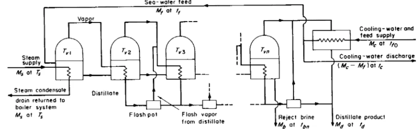
The simplest conceptual scheme of distillation, which was in fact also the first used historically, is indicated in Fig. 3.5. T h e sea water is boiled in a vessel, using steam as the heating medium. T h e vapor is condensed by heat extraction to a cooling supply of sea water, part of which forms the feed to the plant. T h e temperatures we shall be dis
cussing are defined in the diagram. Clearly, tc and tfl are in this case
Steom supply Ms ot rs
Steam condensate drain returned to boiler system Ms at Ts
Vapor M„ at Γ
Sea-water feed Mf ot / / ,
Reject brine MM at th
Cooling-water and feed supply Mc ot ffo I Cooling-water discharge
' ( M-Mf) at tc , Distillate product
F I G . 3.5. Boiling-system distillation—Single Effect.
88 R. S. SILVER
R La + [sd(td - tf0) - sf(tfl - tf0)] + (Mb/Md)[sb(tb - tf0) - sf(tc - tf0)] ' (3.22) equal, with tf0 being the basic sea water temperature. T h e heat supply from the steam has to satisfy the equation (neglecting the complication of pumping meantime)
Η = sfMf(tb - tn) + MdLs. (3.17) Also
MdLd = Mc{tc - tf0)sf
= Mc(tfl - tf0)sf . (3.18)
In the over-all balance,
Η = Mbsb(tb - tf0) + Mdsd(td - tf0) + (Mc - Mf)sf(tc - tfQ). (3.19) Substitution from (Eq. 3.18) into (Eq. 3.19) gives
Η = Mbsb(tb - tf0) + Mdsd(td - tf0) + MdLd - Mfsf{tc - tf0).
(3.20) From the mass balance, Mf = Mb + Md ; hence
Η = MdLd + Md[sd(td - tf0) - sf(tn - tf0)]
+ Mb[sb(tb - tf0) - sf(tc - tf0)]. (3.21) Now from the nature of the heat-exchange process we must always
have Tv > tc ; therefore, td > tc = tfl > tf0 . Also sf < sd , since the feed contains salt, whereas the distillate is pure water which has a higher specific heat. Hence the coefficient of Md in the second term is always positive.
In the third term, although sb is slightly less than sf because of increased concentration, tb > Tv because of boiling-point elevation, and hence tb
is necessarily still more in excess of tc. Thus the coefficient of Mb is also positive.
Thus if we neglect power consumption and put the heat input in Eq. (3.4) equal to H> then
Md/H = RIIOOO and
1000
Equation (3.22) is exact. However, for illustration purposes let us for the present ignore the differences of specific heat due to concentration, and take sd , sf, and sb all approximately equal to each other, i.e., equal to the specific heat of pure water sd . Then
1000
Ld + sd[(td - tn) + {MbIMa)(tb - tc)]
Now tc = tfl and tb = td + Δίχ , where Atx is the boiling-point elevation.
Therefore,
73 ^ 1000
• Ld + sd{(td - tfl)[l + (Mb/Md)]} + sd(Mb/Md) Atx ' ^ J) It is important to note that, for this simple system, the proposals that have been made to install liquid/liquid heat exchangers to recover heat from the exit brine and exit distillate are quite useless. T h e key matter is that the vapor produced has to be condensed. A n y recovery from the brine or the distillate could only be used to heat the feed water, and if this were done, the circulating water supply to the condenser would need to be increased.
Hence with single evaporation, R cannot be made greater than the value, given by Eq. (3.22) or approximately by Eq. (3.23).
Equation (3.23) shows that, if evaporation is conducted in the region around atmospheric pressure, where Ld is of the order of 1 0 0 0 Btu/lb, R cannot be greater than of order unity with single evaporation. In the other terms of the denominator, td — tfl is the terminal heat-exchanger- design temperature d i f f e r e n t which 'will be of order 10°F. T h e ratio MbjMd is usually at least unity, because one does not normally allow the concentration to rise beyond about twice the sea-water figure.
Equation (3.23) also reveals the origin of proposals for reduction of distillation costs by using high-pressure, near-critical single evaporation.
It is then assumed that Ld can be made very low or vanish altogether, giving high values of R. However, more careful examination of Eq. (3.23) throws considerable doubt on the utility of this proposal. T h e term in Atx , which is small at atmospheric pressure, may become very con
siderable at high pressure. This is easily seen if we consider the thermo
dynamics of the theory of dilute solutions. W e have, approximately, (3.23a)
90 R. S . SILVER
where C is the weight-by-weight concentration, Rg is the gas constant, and td is the pure-liquid boiling-point absolute. Thus as Ld diminishes with rising temperature and pressure, Atx increases. It is easy to show that the denominator of Eq. (3.23) therefore has a minimum value—if we consider a range where td is nearly constant—when
J? t 2
*π.
€ΎΓ =
ι-
(3-
23b)Considering the case of (Mb/Md) = 1, i.e., concentrating sea water to twice its original concentration, for which case C = 0.07 and sd = 1 Btu/lb-°F, Rg = 0.11 Btu/lb-°F, we obtain tJLd = 11.4°R-lb/Btu.
This is only satisfied near the critical point. At td = 700°F = 1160°R, we haveLrf = 172 Btu/lb, so that td/Ld = 6.7°R-lb/Btu. At 705°F = 1165°R, we h a v e Ld = 69 Btu/lb, giving tJLd = 16.8°R-lb/Btu. This shows that the assumption of constant td is a good enough approximation. W e need Ld = 1160/11.4 = 102 Btu/lb for the minimum denominator in Eq. (3.23).
This indicates 704°F as the appropriate condition, for which the pure water-saturation pressure is 3 1 7 7 psia. W e now examine the minimum limit condition of the denominator of Eq. (3.23). Neglecting the second term and substituting for the third term using Eq. (3.23a) and (3.23b), we see that the denominator becomes 2Ld , i.e., 204 Btu/lb.
Hence it follows that R max = 5, i.e., that near critical pressure, single distillation cannot give R any higher than 5.
In fact we have a further correction to make, because at the tem
peratures indicated, sd is very far from 1 Btu/lb-F. It is about three times that quantity! The result of this correction is to reduce the temperature for the minimum denominator to 700°F, where Ld = 170 Btu/lb-°R. Hence 2Ld = 340 Btu/lb-°R. Hence in fact the best
value of R by this method cannot be greater than 3.
Proponents of high-pressure or supercritical distillation have usually regarded the problems of scale prevention and of pressure design as the main hindrances to its success. The above argument shows the much more conclusive point that it cannot give high fuel economy.
(We have in addition not allowed for the great increase in pumping power with high-pressure operation.)
Although the thermodynamics of dilute solutions and perfect gases does not exactly apply to our system, the order of magnitude and the general nature of the variation of Atx can be accepted, and hence we conclude that by no possible means can single evaporation distillation give R > 3, and in the convenient range of temperature and pressure operation will give only R = 1.
2. Heat-Transfer Surface
T w o sets of heat-transfer surface have to be provided. These, with their respective thermal loads and temperature differences, can be specified as in Table 3.1.
T A B L E 3.1
Function Surface
T h e r m a l load
Effective temperature
difference
Over-all heat-transfer-
coefficient symbol
Evaporation se ˙ = MSLS T8 - h v.
Condensation MdLd tfi tfo
Condensation MdLd
l n [ ( Tr - tf„)l(Tv - * )]
Now from Eq. (3.4), Η = 1000 Md/R, and, from Eq. (3.22), MdLd = - Md[sd(td - tf0) - s,(tn - tf0)]
- Mb[sb(tb - tf0) - sf(tc - tn)].
Using instead the approximations summarized in Eq. (3.23), we get MdLd = IOO0MJR - sd(td - tn)(Md + Mb) - sdMb Atx .
Now if the condenser design is assumed to have negligible pressure drop on the vapor side, we have Tv = td . Hence
_ _ 1000Md 1000Md
UeR(Ts - tb) UeR(Ts - td- Atx) and
S c = H i * * - J ^ - * n ) l rlOOOM, _ S d { ta _ t n ) { Ma + ^ _ A t J[
(3.25) For analysis of condenser-surface design it is often convenient to use the logarithmic mean-temperature difference in the expanded form given by the relation
β _ *η ~~ tro td ~ tfo β 26)
l n [ ( * d - tf0)/(td - tfl)] i + ± k + ±k* + \k* + - ' K ' }
92 R . S . SILVER
where
^ = (*η — */o)/(*d — tfo)-
Thus θ is expressed now in terms of the maximum temperature difference between vapor at td and entrance cooling water at tf0 , and of the ratio k which the cooling-water temperature rise bears to that maximum.
Substituting Eq. (3.26) in Eq. (3.25) and neglecting terms other than 1000 Md/R (since R in this case is small), we obtain for the total heating surface required per unit rate of distillate product,
ST = Se + Sc
Md Md
looo ι Ø + & + -
R Ue(Ts - td- Atx) + Uc(td - tf0) ' V' , ] It is clear that there must be an optimum choice of operating evapora
tion temperature td between the steam temperature 7^ and the sea-water temperature tf0 .
W h e n this point is investigated by differentiating, treating k as a constant which may be fixed by design, we find that the optimum value of td is given by
t * tf0 + a^(Ts-Atx)
where a = f(k)UJUc and f(k) = 1 + \k + %k2 + \k* + —, and the corresponding minimum total surface required is found to be
ST* _ 1 0 0 0 j* 1 / / ( * ) \1 / 212 Md - R(TS - Atx - tf0) L(C/e)1/2 + \ u j J ·
B . MULTIPLE-EFFECT DISTILLATION
1. Over-all Performance
In this section we shall discuss circumstances in which there is a series of vessels spanning the working temperature range for a plant.
The actual latent heat of evaporation is therefore different in each effect. However, for simplicity and analytical convenience we shall assume constant latent heat denoted by L. T h e range in actual plant is from 2 5 0 to 100°F, in which L varies from 9 6 0 to 1040 Btu/lb.
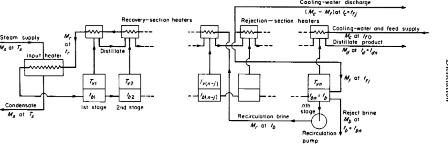
T h e basic concept of improving the performance ratio R from that obtainable by a single evaporation is illustrated in Fig. 3.6. Here several vessels are placed in series. T h e first, which is at the left side of the figure, corresponds exactly to the vessel of Fig. 3.5 in that the feed
93
FIG. 3.6. Boiling-system distillation—multiple effect, poor design.
94 R. S . SILVER
enters it after passing, along with circulating water, through the terminal condenser, and also in that steam heating is similarly supplied to this vessel at lower temperature and pressure. However the vapor boiled off is not condensed by circulating water, but is condensed by being used to evaporate vapor from brine in the second vessel. This process is continued in series down the chain. It is customary to call each vessel an "effect," so that what we have is multiple-effect distillation, each effect being at progressively lower temperature and pressure. The vapor produced from the final effect is condensed by a circulating water stream.
Figure 3.6 represents a rather unsophisticated way of engineering multiple-effect distillation because of the considerable thermodynamic irreversibility associated with the relatively cold feed at tfl entering the highest temperature vessel. The obvious alternative of pumping the feed up the vessels instead of cascading the brine down as shown in the figure has the disadvantage of giving the highest salt concentration at the highest temperature and of giving the brine reject at a high tem- perature, thus requiring liquid/liquid exchangers to restore economy.
The optimum method in this system is shown in Fig. 3.6.
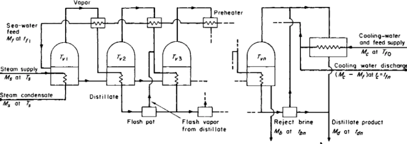
It will be seen that irreversibility is reduced by using some of the vapor condensation from each effect to preheat the feed. W e shall therefore, discuss the multiple-effect system, with reference to its most developed form, as shown in Fig. 3.7.
Here the distillate stream is provided with flash pots between each effect, so that the available heat from the distillate temperature descent may also be used in the best form. (Obviously it could also be used in a liquid/liquid exchanger but with poorer heat-transfer performance.) The downward cascading of brine also produces a fraction of vapor by flashing in each effect. Hence not all the vapor produced from each effect is obtained by actual boiling—nor, because of the preheaters, is all the vapor condensed by giving heat to boiling. Since the cumulative distillate and net brine constitute the constant amount Mf, the total amount of vapor flashed off from both sources is proportional only to the temperature drop between effects. Hence the condensation of this amount of vapor could give sufficient heat to give the feed stream Mf
a temperature rise equal to the temperature drop between effects.
Now from the surface optimization discussion in Section II, A, 2, we may assume, although this can of course be proved rigorously, that, given uniform heat-transfer coefficients, optimum design occurs when the total effective temperature difference is evenly divided between effects. Hence the preheaters should be designed to give equal tem- perature rises that are also equal to the temperature drop between effects.
95
FIG. 3.7. Boiling-system distillation—multiple effect, improved design.
96 R. S . SILVER
It follows from the preceding remarks that the amount of vapor condensed in the preheater is therefore best designed as approximately equal to the amount of vapor produced by flash from the cumulative distillate and net brine, i.e., the preheating is effectively the same as if we had simple contraflow heat exchange between the two streams, each Mf
moving in the opposite direction, with part of the heat input in the first effect giving the necessary temperature difference.
Since this applies to each preheater, we may therefore, to a good approximation, discuss the situation on the assumption that the evapora
tion amount (and corresponding condensation amount) in each effect is equal. Although not exact, owing to the variation of latent heat, it is sufficient for general analytical purposes to make this assumption. (In practical design, it cannot of course be assumed. T h e variation of latent heat shifts the optimum slightly from the equal-temperature-interval specification.) Then we may say that of the distillate amount Md(l — I) which is produced by actual boiling, Md(l — l)/n is obtained in each effect, if there are η effects.
The amount lMd is produced by flashing, and it is important not to confuse this with the total amount of vapor condensed in preheaters.
Flash from cumulative distillate is useful to give a contribution to heat, but it does not give a contribution to new distillate. Hence we must calculate lMd as follows.
Let y — tbr — tbir+1) be the equal temperature-drop interval between effects. The amount of brine which flows from E1 to E2 is Mf — [Md(l — l)]/n, and hence the flash from it is
M„(l - /)
Thus the amount of brine flowing from E2 to E3 is
M
d( l - / ) _ y r M
d(l-/)n
L i 1
and the flash from it is again obtained by multiplying by the factor sby/L.
W e note that sbyjL is very small ( = 10/1000 = 0.01), and hence we can neglect second-order terms in the quantity when summing to a finite value of n. Hence our series becomes
n-l ο ¸t n-l
ΙΜΛ = Σ ψ Μ , - %
1 lj r = l L
= Μ. M,(« - 1) - ψ Md(l - I) JL__L . (3.29)
Hence
ι / _ ι hy Mf sby η - 1
1
- - 7 Γ ^ ( « - ί ) + -
Γ( ΐ - / ) — j — ,
and
' - ' = [ ' - ¥ t < " - " ] l ' - ¥ V r '
Again neglecting second-order terms,
Hence
1 - Z = l _ _ _ ( „ - l ) + _ ^ _ . (3.30)
Replacing the average L by the distillate terminal value as an approxi
mation, we find that the thermal load in each evaporator heating surface is given by
Md(\ -l)Ldjn.
This is also the thermal load in the final condenser, part of which is recovered by raising the feed, as part of the circulating water, to the temperature tc. Hence the net heat rejection to the circulating water is
Md(l - l)Ld/n - Mfsf(tc - tf0).
If we now add to this the reject enthalpies of final brine, at tbn , and distillate, at tdn , we obtain the total heat rejection and hence total input, which is, by definition,
1000MJR.
Hence
+ Mbsb(tbn - t,0) + Mdsd(tdn - t/ 0). (3.32) Substituting for the first term on the right-hand side of Eq. (3.32),
using Eq. (3.31), we obtain
1000Md , . \Ld , t . η - 1 , η - 1 . . 1
—R—
=4
η + dn ~ /o) T~ S"y + In S"y ~ i / ( c _ /o)J
+ Mb [sb(tbn - t,0) - ^ L l J _ Sby _ Sf(te - </0)].
98 R. S . SILVER
Now we may suppose that for optimization, tdn — tf0, i.e., the temperature interval between the final effect and the base temperature available should also be y (as it was effectively in the single-effect case).
Hence we obtain finally, again treating all specific heats as equal at sd
and using tbn = tdn + Atxn ,
- R ~ - ^ + S di η { tc tfo)\\l + Mj
+ sd^± Atxn + sd(tdn - tf0) l j ± . (3.33) The similarity of Eq. (3.33) to Eq. (3.23) in Section II, A, 1 will be
noted. In a manner similar to Eq. (3.26), tc — tf0 can be expressed as k(tdn — tf0). W h e n η = 1 is substituted and since tc = tfn becomes tfl, Eq. (3.33) reduces to Eq. (3.23).
There are two chief points to be noted about Eq. (3.33). First of all, since the first term on the right-hand side far exceeds the others, we have necessarily that 1000/i? is of the order of magnitude of Lfn, and hence that R is of the order of magnitude of n. A s we might intuitively expect, three effects will for multiple-effect distillation give a performance ratio of about 3, and so on. Second, since η is an integer larger than unity, there is the possibility that k may be made greater than l/n. In fact, without using excessive pumping power for excessive circulating water through the terminal condenser, it will automatically be greater than l/n, and hence, although of the same order of magnitude, 1000/i?
may be smaller than L/n.
2. Heat-Transfer Surface
W e have assumed that optimization of temperature division is approximately given by
/ΤΊ ˆ ¸ /ΤΙ /ΤΙ ˆˆ% ˆ ¸ ˆˆ% ˆˆ\ ˆˆ% m
-*s * v2 -*v2 «3 * vr 1 vr vn IV*
Hence
·• = T s ~ ^ (3.34)
J ~ n + l ’
i.e., y is the total range between steam temperature and sea-water temperature divided by η + 1.
The temperature difference for the evaporative surface in the rth effect is
Τ vr 1 ^ b r Tvr_i (Tvr - J- Atxr)
= y-Atxr (3.35)
' ln[(T„ - tfr+1)l(Tvr - tfr)]' but for our optimized design (t/r — t/r+1) = y . Hence
¸
Now
Hence
and
Hence
and
H(Tvr-tfr+y)l(Tvr-tfr)] '
tfn tfO = Κ* — tfo) = K^vn ~ */o)
= ky.
tfin-i) — tfo = 0 + k)y
*/<n-2> — ffo = (2 + % , etc.,
tfr tf0 = (n — r + %, Tvr — i/o = (n + 1 — φ .
7\>r — */ r = (1 — k)y
y y
θ* = ln[(2 - k)y/(l - k)y] = ln[(2 - *)/(! - *)] 1 ( 3 3 6)
The thermal load on each preheater is Mfsfy. Hence the total con
densing surface required in all preheaters is
(n-\)Mfsf. 2 - k (
p U ( 3 . 3 7 )
Using our previous definition of /, the evaporative thermal load in the rth effect, excluding the first, is
Md{l-l)L^M±_ ,η-Χ,
η η \ η J
If we neglect the variation in Atxr and use a mean Atx , the temperature difference across the surface in each effect is y — Atx .
The temperature difference for the rth preheater, i.e., the preheater between the rth and (r -f- l)th effect, is
100 R. S . SILVER
η - 1 2n - Hence the required heating surface in the first ettect is
J _ r MaL Mfs[(l/n) - k]y M>s At. n - l -
°x Ue ln(y-Atx) ^ y-At. ^ y - Atx^ m < l Sy 2n(y - Atx).
= _ L [ M*L , M,4(l/n) - k]y M,sAtx
Ue[n(y-Atx)^ y-At. y - Atx
+ •
Mds i{n - \)y y — AtThus the total evaporative heating surface is
1 ^ £ / , l y - J <x v ; ' y - Atx
I Μ / ^ ' . , Mds ,{n-\)y \ kM,sy ι
Finally, the terminal condenser has a mean temperature difference of
tfn tfp _ tfn — tf0 _ ky W(*e - *nW* ~ ^n)] ~~ H(Tvn - tf0)ITvn - «,„)] - ln[y/(l - k)y]
ky
= ln[l/(l - *)]
and a thermal load of
Md{\-l)L MdL M η - 1
Thus the condensing surface required in it is
Therefore we have, for the total evaporative surface in all effects except the first,
5 1U fc^m - M, ^SLe L n(y — Atx) η y — AtJ sb - J L J . (3.38) v ' The evaporative load in the first effect is 1 0 0 0 Md/R. Remembering that
tc == tfn and using Eq. (33) we find that