Óbuda University PhD Dissertation
Tools for Efficient Soft Computing Modelling and Feasible Optimal Control of Complex
Dynamic Systems,
with Application to Multi-Rotor Unmanned Aerial Vehicle Navigation and Obstacle Avoidance
Nemes Attila
Prof. Dr. Mester Gyula
Doctoral School on Safety and Security Sciences
Budapest, 2017
Examination Committee / Szigorlati Bizottság:
Head of the Examination Committee / Elnök:
Prof. Dr. Rajnai Zoltán, egyetemi tanár, ÓE Participants / Tagok:
Prof. Dr. Somló János, egyetemi tanár, ÓE
Dr. habil. Farkas Tibor, egyetemi docens, külső NKE (external)
Public Defence Committee Members / Nyilvános védés bizottsága:
Head of the Defence Committee / Elnök:
Prof. Dr. Rajnai Zoltán egyetemi tanár, ÓE Secretary / Titkár:
Horváthné Dr. Drégelyi-Kiss Ágota egyetemi docens, ÓE Participants / Tagok:
Dr. habil. Molnár András egyetemi docens, ÓE
Dr. habil. Farkas Tibor egyetemi docens, külső, NKE (external) Dr. Tóth András adjunktus, külső, NKE (external)
Reviewers / Bírálók:
Prof. Dr. Kóczy T. László egyetemi tanár, külső, SZE (external) Prof. Dr. Szabolcsi Róbert egyetemi tanár, ÓE
Budapest, 2017.
………..
CONTENTS
INTRODUCTION ... 8
Formulation of the Studied Scientific Problem ... 8
Research Objectives ... 9
Research Hypothesis ... 10
Research Tools and Thesis Validation Methods ... 11
1 QUADROTOR UNMANNED AERIAL VEHICLES ... 13
1.1 Modelling Multi-rotor Flight Dynamics ... 13
1.2 Unmanned Aerial Vehicles Path Tracking Control Solutions ... 18
1.2.1 PID Controllers with Fuzzy Systems Based Adaptive Gain Parameters .... 18
1.2.2 Lyapunov Stable Back-stepping Control with an Adaptive Fuzzy Model . 19 1.2.3 Direct PD Like Fuzzy Controllers for Position and Altitude Control ... 21
1.2.4 Fuzzy Control System Based Visual Servoing ... 21
1.2.5 Fuzzy Controller Performance ... 23
1.2.6 Adaptive Fuzzy Back-stepping Control ... 23
1.3 Conclusions of Analysing Literature on Soft-computing Autonomous Multirotor Navigation with Obstacle Avoidance ... 23
2 GENETIC ALGORITHMS FOR MULTI-OBJECTIVE SEARCH AND OPTIMISATION ... 26
2.1 Literature Synopsis ... 26
2.1.1 Sum–dominance Vector Comparison Method ... 28
2.1.2 Sum–dominance Vector Comparison Method ... 29
2.1.3 Overview of MOGA – Block Type Non-dominance Ranking ... 29
2.1.4 Overview of NSGA – Slice Type Non-dominance Ranking ... 30
2.1.5 Overview of Pareto-dominance ... 30
2.1.6 Validating Quality of Multi-objective Search and Optimisation ... 31
2.1.6.1 Simple Two Objective Optimisation Problem ... 32
2.1.6.2 Deceptive Multiobjective Optimisation Problem ... 33
2.1.6.3 Multimodal Multiobjective Problem ... 34
2.1.6.4 Convex and Nonconvex Paretooptimal Fronts ... 35
2.1.6.5 Discontinuous Paretooptimal Front ... 37
2.1.6.6 Biased Search Space ... 38
2.1.6.7 Generalisation of Two Objectives to Four Objectives ... 39
2.2 New Scientific Achievements ... 40
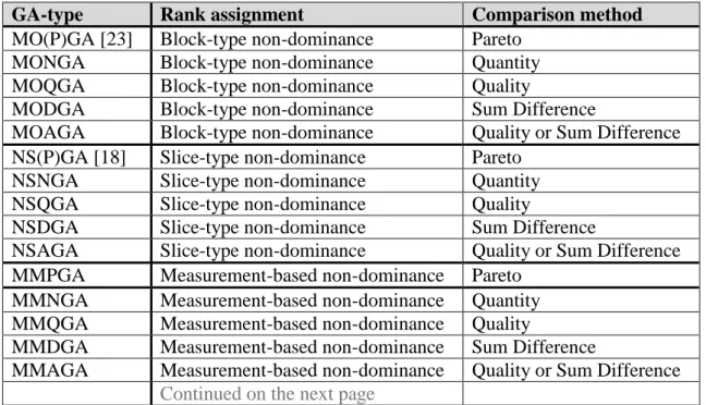
2.2.1 New Vector Comparison Operators ... 40
2.2.1.1 Quantity-dominance Vector Inequality Operator ... 40
2.2.1.2 Quality–dominance Vector Inequality Operator ... 43
2.2.1.3 Any–dominance Vector Comparison Method ... 44
2.2.1.4 Non-dominance Measurement Based Ranking ... 45
2.2.1.5 Dominance Based Ranking ... 45
2.2.1.6 Dominance Measurement Based Ranking ... 46
2.2.2 Implementation of New Multi-objective Genetic Algorithms ... 46
2.2.3 Results of Multi-objective Genetic Algorithm Evaluations ... 48
2.2.3.2 Results of Ranking Method Analysis ... 49
2.2.3.3 Results of Multi-objective Genetic Algorithms Analysis ... 50
3 UNIVERSAL FUNCTION APPROXIMATION BY FUZZY SYSTEMS ... 55
3.1 Literature Synopsis ... 55
3.1.1 Fuzzy System Modelling by Zadeh-formed Membership Functions ... 55
3.1.2 Fuzzy Partitions ... 57
3.1.3 Validating Quality of Genetic Fuzzy System Function Approximation ... 57
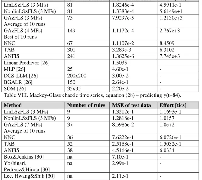
3.1.3.1 Chaotic Time Series of Mackey and Glass ... 57
3.1.3.2 Gas Furnace Model of Box and Jenkins ... 58
3.1.3.3 Generalised Rastrigin Function ... 59
3.2 New Scientific Achievements ... 60
3.2.1 New Minimalistic Parametrisation of Zadeh-type Fuzzy Partitions for
Function Identification by Unconstrained Tuning ... 60
3.2.2 Implementation of the New Genetic Fuzzy System Parametrisation ... 61
3.2.3 Results of the New Function Identification with the New Genetic Fuzzy System Parametrisation ... 62
4 GENETIC FUZZY MODELLING OF COMPLEX SYSTEM DYNAMICS ... 67
4.1 Literature Synopsis ... 67
4.1.1 Modelling Robot Manipulator Dynamics ... 67
4.1.2 Modelling Multi-rotor Flight Dynamics ... 68
4.1.3 Validating Quality of Complex Nonlinear Dynamic System Genetic Fuzzy System Modelling ... 70
4.1.3.1 SCARA Robot Manipulator as Modelling Test System ... 70
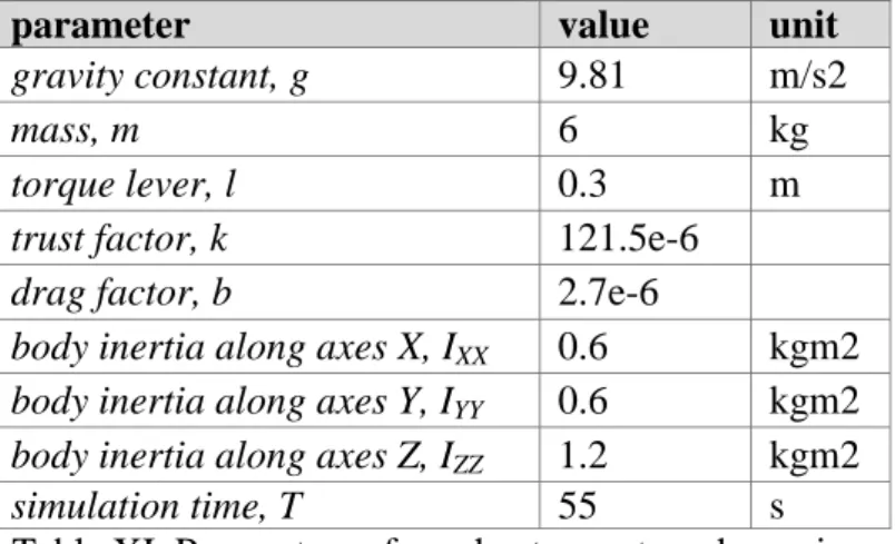
4.1.3.2 Quadrotor Unmanned Aerial Vehicles as Modelling Test System ... 70
4.2 New Scientific Achievements ... 71
4.2.1 New Genetic Fuzzy System Grey-box Modelling of Complex Dynamics Systems ... 71
4.2.2 Implementation of the New Genetic Fuzzy System Grey-box Modelling of Robot Manipulator Dynamics ... 72
4.2.3 Results of the New Genetic Fuzzy System Grey-box Robot Manipulator Modelling ... 73
4.2.4 New Continuous Periodic Fuzzy Logic Systems ... 76
4.2.5 New Genetic Fuzzy System Grey-box Modelling of Multi-rotor Flight Dynamics ... 78
4.2.6 Implementation of New Genetic Continuous Periodic Fuzzy System Grey- box Modelling ... 78
4.2.7 Results of New Genetic Continuous Periodic Fuzzy System Grey-box Modelling of Multi-rotor Flight Dynamics ... 83
5 OPTIMAL SYSTEM TRAJECTORY DESIGN ... 88
5.1 Literature Synopsis ... 88
5.1.1 Basic Approaches to Optimal Trajectories ... 88
5.1.2 Multi-Rotor Unmanned Aerial Vehicle Flight Trajectory ... 92
5.1.3 Electric Motors as Actuators ... 94
5.1.4 Often Neglected System and Actuator Characteristics, Effects of Infeasible Trajectories ... 95
5.1.5 Validating Quality of System Trajectory ... 96
5.1.5.1 Multi-rotor Test Flight Trajectory ... 96
5.1.5.2 3D Overhead Crane Test Trajectory ... 96
5.2 New Scientific Achievements ... 97
5.2.1 New Feasible Optimal Harmonic Trajectories of Bounded, Smooth Time Derivatives ... 97
5.2.2 New Feasible Optimal Harmonic Multi-rotor Flight Trajectories ... 99
5.2.3 Implementation of the New Feasible Optimal Harmonic Multi-rotor Trajectories of Bounded, Smooth Time Derivatives ... 102
5.2.4 Results of the New Feasible Optimal Harmonic Multi-rotor Flight Trajectories of Bounded, Smooth Time Derivatives ... 105
5.2.5 New Feasible Optimal Harmonic 3D Overhead Crane Trajectories ... 115
5.2.6 Implementation of the New Feasible Optimal Harmonic 3D Overhead Crane Trajectories of Bounded, Smooth Time Derivatives ... 116
5.2.7 Results of the New Feasible Optimal Harmonic 3D Overhead Crane Trajectories of Bounded, Smooth Time Derivatives ... 116
6 GENETIC FUZZY SYSTEM TRAINING DATA SET REDUCTION ... 127
6.1 Literature Synopsis ... 127
6.1.1 Validating Quality of Genetic Fuzzy System Training Data Sets ... 127
6.2 New Scientific Achievements ... 128
6.2.1 New Singular Value Decomposition Based Genetic Fuzzy System Training Data Set Reduction ... 128 6.2.2 Implementation of New Singular Value Decomposition Based Genetic
6.2.3 Results of New Singular Value Decomposition Based Genetic Fuzzy
System Training Data Set Reduction ... 130
SUMMARY CONCLUSIONS ... 131
New Scientific Achievements ... 131
Application Possibilities of Results ... 133
REFERENCES ... 139
Publications in Support of Thesis ... 144
Further Publications ... 145
ABBREVIATIONS ... 147
LIST OF TABLES ... 149
LIST OF FIGURES ... 150
APPENDIX I ... 153
Box-Jenkins Gas Furnace Benchmark Data ... 153
APPENDIX II ... 156
Effects of Displacement Jerk, Snap and Pop Function Discontinuities on Multi-rotor Flight Dynamics ... 156
Discontinuity in d3r/dt3 – jerk ... 156
Discontinuity in d4r/dt4 – snap ... 161
Discontinuity in d6r/dt6 – pop ... 168
INTRODUCTION
Formulation of the Studied Scientific Problem
The focus for this dissertation is on studying mechanical systems of complex dynamics.
Unmanned aerial vehicles and robotic manipulators are typical examples of complex dynamics systems. The difficulty in wide spread studding robotic manipulators lies in their relative low availability and high cost. A wide area of robotics research is dedicated to aerial platforms, which have very similar dynamics and are more simple to build and also commercially available in wide ranges. Versatile flying structures and configurations have been developed to allow 3D movements [35], [60]. For example, there are blimps, fixed-wing planes, single rotor helicopters, bird-like prototypes, quadrotors, hexa-rotors, octa-rotors, etc. Each of these has advantages and drawbacks.
The vertical take-off and landing (VTOL) requirements exclude some of the aforementioned configurations.
The quadrotor architecture has low dimensions, good manoeuvrability, simple mechanics and good payload capability. The main drawback is the relatively high energy consumption and difficult precision flight control; however, the trade-off results are very positive. This structure can be attractive in several applications, in particular for surveillance, for imaging dangerous environments, and for outdoor navigation and mapping. The study of kinematics and dynamics helps to understand the flight mechanics of the quadrotor and its behaviour [33], [12]. Together with system modelling, the definition of the control algorithm structure is very important. Soft computing methods can be efficiently applied together with, and even instead of conventional controllers [63].
Multi-rotors like quad- and hexa-rotors are popular representatives of VTOL unmanned aerial vehicles (UAVs) as they are relatively simple to build, while being of versatile applicability, also capable of vertical take-off and landing. Also the multi-rotor architecture has simple mechanics, high relative payload capability and good manoeuvrability. The study of multi-rotor kinematics and flight dynamics is based on the physics of aerial platforms - flying bodies, a good description of such can be found in [35]. The kinematics and general force and torque dynamics, flight mechanics of any symmetric multi-rotor (quad-, hexa- or any other number of rotors) is equivalent.
This work presents an efficient toolset improvement proposal for multi-rotor aerial vehicles control system design. Efficient autonomous navigation and obstacle avoidance requires a fast, direct method for calculating time and energy efficient feasible trajectories. Efficient control systems in real-life outdoor environment require robust adaptive system models. Designing robust fuzzy systems require efficient global and precise local optimisation techniques.
The first part of this theses collection proposes improvements of multi-objective stochastic search by a new vector comparison ordered inequality operator and ranking method. The efficiency analysis of the new method is presented on well-studied genetic algorithms of proven convergence capability and carefully designed, mathematically sound, difficult multi-criteria optimisation problems of various Pareto-front form and search space density.
The second part proposes a novel representation of fuzzy-partitions based inference
representation of non-linear parameters of these systems makes it possible to be subjected to efficient unconstrained optimisations by global search algorithms and fine- tuning with gradient descent based methods. Linear parameters of these fuzzy-systems are best calculated based on singular value decomposition to achieve mean square error minimisation. The new multi-objective stochastic search methods introduced in the first part are used to find non-dominated fuzzy system solutions where both the fuzzy structure complexity, the number of membership functions and rules, and the function approximation error, both the absolute maximum error and the mean square sum of the error is first globally minimised then locally fine-tuned by a gradient descent method.
The third part proposes a new method for robust fuzzy-system based modelling of complex dynamic systems as robot manipulators and mobile robots, like free flying multi-rotors. For the six degree of freedom multi-rotors a special extension is proposed for periodic continuous extension of fuzzy systems. This new method follows the grey box identification approach, making use of well-known system properties of robotic manipulators. My proposal results in a system approximation, which has all the benefits of robust fuzzy systems, and also manifests all the analytical properties of dynamic models that are used for analysing system and system control properties. Application of these fuzzy system based grey box models in classical hard computing control techniques is straightforward, as it is possible to explicitly analytically extract all system states and their derivatives.
The fourth part introduces a direct, iteration free single-pass algorithm using simple closed formulas, to design time and energy efficient trajectory parametrisations with pre-defined time derivative constraints. The method enables designing trajectories tuned to system (including control actuator) capabilities and ensuring oscillations free control possibilities. The method is presented for both multi-rotor trajectory designs, where higher derivative smoothness is a must for efficient control, and it is also presented for 3D overhead crane trajectory designs to analyse its oscillations free property.
The fifth part presents a new method for fuzzy-system training data set reduction.
Research Objectives
As concluded and highlighted in the introductory chapter for efficient multi-rotor autonomous navigation and obstacle avoidance improvement it is necessary to master the following design and engineering tools:
1. Efficient multi-objective search
My first goal is to define a new operator for comparing two vectors, which can be used as basis for an efficient multi-objective ranking method for Genetic Algorithm (GA), which performs better than the existing Pareto dominance based algorithms.
2. Efficient genetic fuzzy system universal function approximation
My second goal is to define a new method for an efficient unconstrained optimisation of Takagi-Sugeno-Kang (TSK) Fuzzy Logic Systems (FLS) subject to both a GA based global search and further ANFIS like gradient descent based local fine tuning of fuzzy partition antecedent Membership Function (MF) parameters. The MF rule base has to remain intact; complete fuzzy partitions have to remain with keeping the pre-defined linguistic variable order. The resulting FLS has to be capable of acting as a universal function approximation.
3. Efficient robust modelling method for autonomous control of complex systems of nonlinear dynamics
My third goal is to define a new efficient robust system dynamics modelling method, which results in a system model that can be readily used for efficient autonomous, system state model based control of complex nonlinear dynamics systems such as robot manipulators (RM) and multi-rotor unmanned aerial vehicles (UAV) navigation dynamics.
4. Efficient trajectory design method for autonomous control of complex nonlinear dynamic systems
My fourth goal is to define a new method for an efficient real-time direct path parametrisation design algorithm for generating physically feasible, time-and energy optimal, bounded, continuous trajectories that induce no system oscillations. The notion of time and energy optimality is not to be used in some mathematics theory manner but in real life physically feasible engineering manner. Finding optimal trajectories is focused on finding the appropriate parametrisation for the path vector function, given the pre-defined feasibility limits on the displacement time derivatives.
5. Efficient genetic fuzzy system training data set reduction method
My fifth goal is to define a new method for an efficient genetic fuzzy system (GFS) training data set reduction, which will significantly reduce the data set size, while maintaining the quality of the identification process, and thus significantly increase the identification process performance, independent of the system to be identified.
Research Hypothesis
Hypothesis I: there exists a vector comparison method which is capable of guiding a multi-objective stochastic search more efficiently than the Pareto dominance relation.
Hypothesis II: there exists a more suitable parametrisation method for antecedent fuzzy partition MF components of a TSK FLS, which is still simple to directly compute and optimise without any restrictions, both by stochastic search and/or with gradient descent methods; and for every case the formed parameters will inherently satisfy all of the required constraints for a stable fuzzy partition antecedent structure, keeping the associated linguistic values.
Hypothesis III.a: the singular value decomposition (SVD) algorithm is efficient enough to extract each basic component of a dynamic system described by Euler-Lagrange equation, when there are a sufficient number of good quality training samples available.
Further on the nonlinear inertia component functions can be robustly identified with TSK FLSs, while the nonlinear functions describing the centrifugal and Coriolis effects can be exactly derived from the identified TSK FLSs for the inertia components. The nonlinear parameters of TSK FLSs modelling a Robotic Manipulator (RM) dynamic system can be efficiently found by a multi-objective hybrid GA together with gradient descent method fine-tuning, while all the linear parameters of the used TSK FLSs, including constants of the model can be directly calculated with SVD based robust least squares (LS) method. The RM trajectory used for collecting training samples have to be sufficiently exciting to reveal all the characteristics of the RM system equation.
Hypothesis III.b: it is possible to extend the TSK FLSs in a way that they become periodic and of continuous output, even for the 0-2𝜋 transitions of attitude Euler angle system inputs. Then for modelling multi-rotor flight dynamics each nonlinear component of a flight dynamics formulated by Euler Lagrange approach can be identified in a similar manner as stated in my previously described hypothesis III.a for RMs.
Hypothesis IV: system trajectories can be designed in harmony with the system dynamics and its actuator characteristics. Such trajectories are energy efficient as no oscillations are induced, and they are feasible, time optimal in terms that no trajectory exists with faster transients, such that the system can precisely track it with lesser energy consumption. These harmonic trajectories are continuous up to the required number of time derivatives, and they can be made bounded in their any number of time derivatives. For a realistic, feasible control input of multi-rotor UAV the designed path has to be such that the sixth time derivative of the body displacement function must be continuous and its fourth time derivative transient has to be feasible for the control actuator. For a realistic, feasible control input of direct brushless DC electric motor (BLDC) actuated systems (RMs, cranes, wheeled vehicles) the designed path has to be such that the fourth time derivative of the planned displacement must be continuous, while the planned body rotation must be such that the feasible body torque transients are proportional to the possible motor torque transients; equivalently the feasible second derivative of the body displacement has to be proportional to motor shaft feasible angular velocity.
Hypothesis V: for dynamic system GFS identifications the necessary training data set of collected samples along real trajectories can be reduced without significant loss in the quality of the identification result, while significantly improving the efficiency of the identification process.
Research Tools and Thesis Validation Methods
From the first introductory chapter it is obvious that my research is multidisciplinary, as such various research and test methods are necessary to test my hypothesis. As my goals are more general than finding a single specific method which is only applicable to UAV design, but are applicable to wide range of multidisciplinary field, I and not using a single UAV example to validate my theses. For each hypothesis I am also using a method well matched to the nature and specifics of the problem, so that my results are appropriately tested and presented in a general way.
1. Validating Quality of Multi-objective Search and Optimisation
The proposal is to be validated on well-studied, mathematically sound GA hard multi- objective benchmark problems like:
a) Simple Two Objective Optimisation Problem b) Deceptive Multiobjective Optimisation Problem c) Multimodal Multiobjective Problem
d) Convex and Nonconvex Paretooptimal Fronts e) Discontinuous Paretooptimal Front
f) Biased Search Space
g) Generalisation of Two Objectives to Four, Eight and Sixteen Objectives 2. Validating Quality of Genetic Fuzzy System Function Approximation
The proposal is to be validated on well-studied, mathematically sound, versatile, difficult benchmark identification problems of high complexity like:
a) Predicting Future Values of Chaotic Time Series of Mackey and Glass b) Identification of Gas Furnace Model of Box and Jenkins
c) Identification of Generalised Rastrigin Function
3. Validating Quality of Complex Nonlinear Dynamics System GFS Modelling
The proposal is to be validated on well-studied robot manipulator dynamics modelling and quadrotor flight dynamics modelling simulations.
4. Validating Quality of System Trajectory
The proposal is to be validated on well-studied 3D crane and quadrotor flight trajectory design.
5. Validating Quality of Genetic Fuzzy System Training Data Sets
The proposal is to be validated on well-studied quadrotor flight dynamics modelling simulations.
1 QUADROTOR UNMANNED AERIAL VEHICLES
This chapter describes the system in focus of this research – the multirotor unmanned aerial vehicle and the existing major tools used to achieve system control suitable for its autonomous navigation and obstacle avoidance.
As well summarised in [60] [63] rotary wing aerial vehicles have distinct advantages over conventional fixed wing aircrafts in surveillance and inspection tasks because they can take-off and land in bounded spaces and easily fly above the target. A quadrotor is a four-rotor copter. An example of one is shown in Figure 1 [60].
Multirotor copters are theoretically dynamically stable, but of poor stability augmentation and of limited control authority, thus very difficult to control; suitable advanced robust control methods are needed to make them steadily manoeuvrable.
Although a very sensitive dynamics is not desirable from control stability point of view, it is good from the system agility, manoeuvrability point of view. The system complexity comes from wide range of changes in the rotorcraft parameters and from unpredictable real-life environmental disturbances such as a wind gusts or air density variations.
Figure 1.
3 D motion, commonly used model of the quadrotor [60].
1.1 Modelling Multi-rotor Flight Dynamics
A quadrotor is controlled only by varying rotor speeds, thereby changing the lift forces and rotor torques [33], [12]. It is an under-actuated dynamic vehicle with four input forces and six outputs coordinates. One of the advantages of using multi-rotor copters is the increased payload capacity. Quadrotors are highly manoeuvrable, which allows for vertical take-off and landing, as well as flying into hard-to-reach areas. Disadvantages are the increased rotorcraft weight and increased energy consumption due to extra motors. Since the machine is controlled via rotor speed changes, it is more suitable to utilize electric motors. Large helicopter engines, which have a slow response, may not be integrated to a multi-rotor system satisfactory without incorporating a proper gear- box system.
Unlike typical helicopter models and regular helicopters, which have variable pitch angles, a quadrotor has fixed pitch angle rotor blades, and only the speed of individual
rotors is controlled in a suitable manner in order to produce the desired lift force, rotation torques and vehicle position displacements.
The quadrotor is satisfactory well modelled with four rotors in a cross configuration as presented in Figure 1. This cross structure is usually quite thin and light, however it has to show robustness by linking mechanically the motors, which are heavier than the cross structure itself. Depending on the mechanical characteristics of the used electromotor each propeller can be connected to the motor through a reduction gear. Each propeller blade axis of rotation is fixed and they are parallel to each other. Furthermore, they have fixed-pitch blades and their airflows point downwards to get an upward lift. These considerations point out that the structure is expected to be quite rigid and the only characteristics that can dynamically vary are propeller blade rotation speeds.
As shown in Figure 1 [60], one pair of opposite propeller blades of a quadrotor rotates clockwise (rotors 2 and 4), whereas the other pair of blades rotates counter clockwise (rotors 1 and 3). This way it is possible to avoid the yaw drift due to reactive torques.
This configuration also offers the advantage of enabling lateral displacement motions without changing the pitch of the propeller blades. Having fixed pitch rotors significantly simplifies rotor mechanics and reduces gyroscopic effects. Movement direction control of quadrotors is achieved by commanding different speeds to different propellers, which in turn produce differential aerodynamic forces, torques and moments.
For hovering, all four propellers rotate at the same speed. For vertical motion, the speed of all four propellers is increased or decreased by the same amount, simultaneously. In order to pitch and move laterally in a desired direction, speed of propellers 3 and 1 is changed conversely. Similarly, for roll and corresponding lateral motion, speed of propellers 2 and 4 is changed conversely. To produce yaw, the speed of one pair of two oppositely placed propellers is increased while the speed of the other pair is decreased by the same amount. This way, the overall produced thrust is the same, but the differential drag moment creates a yawing motion. Since having only four actuators, the quadrotor is still an under-actuated six degree of freedom (6 DOF) system.
To describe the motion of a 6 DOF rigid body it is usual to define two reference frames:
the earth inertia frame (E-frame), and the body-fixed frame (B-frame) – see Figure 2 [63]. Equations of motion are more conveniently formulated in the B-frame because the inertia matrix is time-invariant, advantage of body symmetry can be taken to simplify equations, also measurements taken on-board are easily converted to B-frame and control forces are readily available in the B-frame.
The E-frame (OXYZ) is chosen as the right-hand reference inertia system. Axis Y points toward the North, X points toward the East, Z points upwards with respect to the Earth, and O is the axis origin. This frame is used to define the linear position (in meters) and the angular position (in radians) of the quadrotor. The B-frame (oxyz) is attached to the multirotor body centre of mass. Axis x points toward the quadrotor front, y points toward the quadrotor left, z points upwards and o is the axis origin. The origin o is chosen to coincide with the centre of mass of the quadrotor cross structure. This reference is right-hand, too.
Figure 2.
Earth- and Body-frames used for modelling of the quadrotor system [63].
The body linear velocity v (m/s), the angular velocity of the body Ω (rad/s), the forces F (N) and the torques T (Nm) acting on the body are defined in this frame. The linear position of the copter (X, Y, Z) is determined by coordinates of the vector between the origin of the B-frame and the origin of the E-frame according to the rotation matrix in equation (2). The angular position or attitude of the copter (𝜙, Θ, 𝜓) is defined by the orientation of the B-frame with respect to the E-frame. This is given by three consecutive rotations about the main axes which take the E-frame into the B-frame. The
“roll-pitch-yaw” set of Euler angles can be used. The vector that describes the quadrotor position and orientation with respect to the E-frame can be written in the form:
𝒒 = [𝑋 𝑌 𝑍 𝜙 Θ 𝜓]𝑇, (1)
where: q is the copter system position and orientation vector; X, Y, Z are the E-frame translational coordinates; 𝜙, Θ, 𝜓 are the “roll-pitch-yaw” set of Euler angles describing the E-frame orientation.
The rotation matrix between the E- and B-frames we conveniently chose to have the following form [8]:
𝑹 = [
𝑐Ψ𝑐Θ −𝑠Ψ𝑐ϕ+ 𝑐Ψ𝑠Θ𝑠ϕ 𝑠Ψ𝑠ϕ+ 𝑐Ψ𝑠Θ𝑐ϕ 𝑠Ψ𝑐Θ −𝑐Ψ𝑐ϕ+ 𝑠Ψ𝑠Θ𝑠ϕ −𝑐Ψ𝑠ϕ+ 𝑠Ψ𝑠Θ𝑐ϕ
−𝑠Θ 𝑐Θ𝑠ϕ 𝑐Θ𝑐ϕ ], (2)
where: R is the rotation matrix between the E- and B-frames; s and c are abbreviations for the sinus and cosine functions of Euler angles as: 𝑠∗ = sin(*), 𝑐∗= cos(*).
The corresponding transfer matrix has the form:
𝑻 = [
1 𝑠ϕ𝑡Θ 𝑐ϕ𝑡Θ
0 𝑐ϕ −𝑠ϕ
0 𝑠ϕ/𝑐Θ 𝑐ϕ/𝑐Θ
], (3)
where: T is the transfer matrix for Euler angle rates between E-frame and B-frame. As in the previous case a notation has been adopted: 𝑠∗ =sin(*), 𝑐∗ =cos(*), 𝑡∗ =tan(*).
The system Jacobian matrix, taking (2) and (3), can be written in the form:
𝑱 = [𝑹 𝟎3𝑥3
𝟎3𝑥3 𝑻 ], (4)
where: 𝟎3𝑥3 is a 3 by 3 zero-matrix.
The generalized quadrotor velocity in the B-frame has a form of:
𝒗 = [𝑥̇ 𝑦̇ 𝑧̇ 𝜙̇ 𝜃̇ 𝜓̇], (5)
where: 𝒗 is the generalized quadrotor velocity in the B-frame; 𝑥̇, 𝑦̇, 𝑧̇ are the B-frame velocities along the appropriate coordinate axis; 𝜙̇, 𝜃̇, 𝜓̇ are the “roll-pitch-yaw” rates of Euler angles in the B-frame.
Finally, as the result of this nomenclature the kinematical model of the quadrotor can be defined in the following simple vector equation form:
𝒒̇ = 𝑱 ∙ 𝒗 (6)
The dynamics of a generic 6 DOF rigid-body system takes into account the mass of the body m (kg) and its inertia matrix 𝑴𝑩 (kgm2). Two assumptions are commonly made:
• The first assumption states that the origin of the body-fixed frame is coincident with the centre of mass of the body. Otherwise, another point should be taken into account, which could make the body equations considerably more complicated without significantly improving the model accuracy.
• The second common simplification assumption specifies that the axes of the B-frame coincide with the body principal axes of inertia. In this case the inertia matrix 𝑴𝑩 is diagonal and, once again, the body equations become simpler.
The dynamic model of a quadrotor can be defined in the following matrix form:
𝑴𝑩𝒗̇ + 𝑪𝑩(𝒗)𝒗 − 𝑮𝑩 = 𝛌, (7)
where: 𝑴𝑩 is the system inertia matrix; 𝑪𝑩 represents the matrix of Coriolis and centrifugal forces; GB is the gravity matrix; 𝛌 is the generalized force vector including forces and torques along body axes. These matrices have known forms as presented in [8].
A generalized force vector 𝛌 has the form:
𝛌 = 𝑶𝑩(𝒗)𝛀 + 𝑬𝑩𝛀𝟐 (8)
where: 𝑶𝑩 is the gyroscopic propeller matrix; 𝑬𝑩 is the movement aerodynamic matrix;
𝛀 is the propellers’ speed vector as defined below in equation (12).
𝑶𝑩, the gyroscopic propeller matrix is:
𝑶𝑩 = [
0 0 0 0
0 0 0 0
0 0 0 0
𝜃̇ −𝜃̇ 𝜃̇ −𝜃̇
−𝜙̇ 𝜙̇ −𝜙̇ 𝜙̇
0 0 0 0 ]
(9)
𝑬𝑩, the movement aerodynamic matrix has the form:
𝑬𝑩 = [
0 0 0 0
0 0 0 0
𝑏 𝑏 𝑏 𝑏
0 −𝑏 ∙ 𝑙 0 𝑏 ∙ 𝑙
−𝑏 ∙ 𝑙 0 𝑏 ∙ 𝑙 0
−𝑑 𝑑 −𝑑 𝑑 ]
, (10)
where b (Ns2) and d (Nms2) are the thrust and the drag factors of one propeller blade; l (m) is the distance between the quadrotor centre of mass and the propeller blade centre of mass.
Equation (11) defines the overall propeller blades rotation speed (rad/s) used in equation (8).
𝜔 = −𝜔1+ 𝜔2− 𝜔3+ 𝜔4, (11)
where: 𝜔 is the overall propellers’ speed; 𝜔𝑖 is the angular speed of the ith propeller.
Positive sign is taken for clockwise rotations and negative sign for counter clockwise rotations.
𝛀, the speed vector of propeller blades is defined as:
𝛀 = [𝜔1 𝜔2 𝜔3 𝜔4]𝑇 (12)
Equations (1) to (12) take into account the entire quadrotor nonlinear flight mechanics model including the most influential aerodynamic effects of rotor blade trust and drag.
For high speed airplanes, it is common to introduce a new 𝑋̂ stability axis, which is aligned into the direction of the oncoming air in steady flight. The stability axis is projected into the plane made by the X and Z body axes when there is sideslip. The used model of quadrotors is not taking into account the sideslip, thus the notion of the stability axis is not used.
High speed aerial platforms in open door environments are highly nonlinear systems also subject to many further nonlinear perturbations like:
i. drag like effects:
a. blade flapping, b. induced drag, c. translational drag, d. profile drag and e. parasitic drag, ii. ground effect,
iii. in vertical descent further nonlinear effects have to be accounted for as:
a. vortex ring state, b. turbulent wake state,
c. windmill brake state as described in [68].
None of these nonlinear effects are commonly considered when modelling multirotor flight dynamics. One feasible approach is to account for these effects as disturbances, which have to be compensated by the controller. In my research I am going one step further, by accounting for all unknown disturbances already in the system model in form of using robust fuzzy systems to initially reduce the effects of all input disturbances.
Precision, robustness and adaptability of the applied dynamic model are the starting point to achieve a precise and efficient autonomous control of the system [1]. Fuzzy systems are capable of robust modelling and control of complex systems including helicopters [71].
1.2 Unmanned Aerial Vehicles Path Tracking Control Solutions
The nonlinear, multivariable and coupled system state and response characteristics make the quadrotor difficult to control. In a general approach two loops are used for the quadrotor UAV control system: the outer loop is the position controller and the inner loop is the attitude controller. The controller of the outer loop for position includes information such as instantaneous position and speed. While the inner loop for attitude controller includes the orientation attitude posture information.
The position controller receives as inputs the difference between the desired E-frame position (X,Y,Z) and the actual current position; the outputs are the required B-frame attitude rotation angles (φ,θ,ψ) to move towards the desired position. The required attitude angles are provided for the attitude controller in the inner loop. The attitude controller outputs the desired propeller blade rotation speed value to each of the four motor controllers, which adjusts the rotation speed of the corresponding motor.
By studding the available literature one can observe that motor controllers are generally taken for granted as mere mathematical tools capable of instantaneously generating any desired rotation speed value, their actual physical dynamics is considered neither for multirotor control, nor for multirotor trajectory design. One of my major research targets is to remedy this deficiency.
Control mechanisms as proportional-integral-derivative (PID) controller, back stepping (computed torque) controller and their fuzzy variants have been also well studied and successfully used for decades on many systems including multi-rotors [s1].
1.2.1 PID Controllers with Fuzzy Systems Based Adaptive Gain Parameters To achieve flight stabilisation and path tracking of quadrotor UAVs, as described in [66] and [34] fuzzy logic systems can be used for adaptive tuning of PID controllers. A PID controller consists of a proportional, an integral and a derivative feedback control action, which represents the current, past and anticipated future errors that cover all the time history of the error signal. The relevant PID gains are named KP, KI and KD. By adjusting these parameters, the desired performance and stability of the system can be achieved. The mathematical representation of PID controller is given as:
𝒖(𝑡) = 𝐾𝑃𝒆(𝑡) + 𝐾𝐼∫ 𝒆(𝑡)𝑑𝑡0𝑡 + 𝐾𝐷𝑑𝑡𝑑 𝒆(𝑡), (13) where: u is the control signal; t is the time; e is the error signal; KP, KI and KD are the PID gain parameters.
PID controllers with fixed gain parameters provide good performance only for linearized systems, or in a single selected narrow quasilinear operation range for nonlinear systems. To overcome the system nonlinearity control problem fuzzy logic systems can be used for adaptive tuning of PID gain parameters [72], [78]. Fuzzy logic consists of four components: fuzzification, fuzzy rule base, inference engine, and defuzzification:
• Fuzzification refers to the process of transforming crisp input values into grades of membership using linguistic terms of fuzzy sets.
• Fuzzy rule base is the main part of fuzzy logic systems. This component is based on if- then rules. The fuzzy rule base defines how to react to each input combination.
• Inference engine applies the fuzzy rule base to form the output for defuzzification.
• Defuzzification is a method to obtain numerical data from the output of a fuzzy rule base.
For a self-tuning fuzzy PID controller the tracking error can be considered as an input for two controllers: first time for a classical PID control algorithm to minimize the position error, and second time to a fuzzy logic system for adjusting the KP, KI, and KD
gain parameters of the PID controller equation (13).
In [66] three fixed position and fixed size triangular membership functions (MFs) were used for fuzzification of the error signal as input and for the gain parameter output. A fixed set of three fuzzy rules were defined. Results of [66] show that the performance of both the classical PID and the fuzzy logic based self-tuning PID control method is acceptable in static cases of no load variation. The self-tuning PID control based on fuzzy logic is able to compensate for variations in payload and to achieve good path tracking. The classical PID control algorithm by itself cannot track the circular path, while the self-tuning PID based on fuzzy logic provides a good performance solution also for this problem [66].
In [34] a wide range of disturbances are modelled. Gravity and buoyancy are combined into a single force. The fluid inertia force related to the acceleration of the rotorcraft motion is represented by additional mass. In the B-frame the direction of the lift force remains constant. While in the inertial system E-frame the driving force of lift is decomposed into three directions along the three coordinate axes. The quadrotor craft is more susceptible to influences of drag, air resistance during flight because of its large surface area. In [34] six fuzzy adaptive controllers are proposed for tuning the gain parameters of PID controllers, having one control output for each state variable of equation (1). For each fuzzy adaptive controller in [34] seven fixed MFs (of linear Z and linear S and of triangular types) are defined for input fuzzification and output defuzzification. The fuzzy rule base is defined constant by expert knowledge. Results in [34] show that for a quadrotor airship model the fuzzy adaptive PID algorithm has a better performance than the classical PID control system.
1.2.2 Lyapunov Stable Back-stepping Control with an Adaptive Fuzzy Model In [15] it is presented how a robust control method with an adaptive fuzzy model can overcome wind disturbance, which buffet the vehicle with periodic wind vortices. For adaptive-fuzzy altitude control of the roll, pitch, and yaw the nonlinear functions of equation (6) are modelled by fuzzy systems. The notation used is as follows – from equation (8), where the generalized force is represented as a vector of control inputs to
each of the quadrotor motors: 𝛌 = [𝑢1, 𝑢2, 𝑢3, 𝑢4]. From equation (1) a new state vector x is derived as 𝒙 = [𝒒, 𝒒̇] so that the system equation (6) becomes of form 𝒙̇ = 𝒇(𝒙, 𝒖) as:
𝒙̇ = 𝒇(𝒙, 𝒖) =
(
𝑥10 𝑥11 𝑥12
𝑥10𝑥12𝑎1+ 𝑥10𝑎2𝜔 + 𝑏1𝑢2 𝑥5𝑥12𝑎3+ 𝑥5𝑎4𝜔 + 𝑏2𝑢3
𝑥10𝑥5𝑎5+ 𝑏3𝑢4 𝑥9 𝑥7 𝑥8
−𝑔 + 𝑐𝑥1𝑐𝑥3𝑢1⁄𝑚 𝑔(𝑥)𝑢1⁄𝑚
ℎ(𝑦)𝑢1⁄𝑚 )
, (14)
where m is the body mass; system parameters ai and bi are defined as:
𝑎1 =𝐼𝑌𝐼−𝐼𝑍
𝑋 , 𝑎2 = −𝐼𝐽𝑟
𝑋, 𝑎3 = 𝐼𝑍𝐼−𝐼𝑋
𝑌 , 𝑎4 = 𝐽𝐼𝑟
𝑌, 𝑎5 =𝐼𝑋𝐼−𝐼𝑌
𝑍 , 𝑏1 = 𝐼𝑙
𝑋, 𝑏2 =𝐼𝑙
𝑌, 𝑏3 =𝐼𝑙
𝑍, 𝑔(𝑥) = (𝑐𝑥4𝑠𝑥5𝑐𝑥6+ 𝑠𝑥4𝑠𝑥6), ℎ(𝑦) = (𝑐𝑥4𝑠𝑥5𝑠𝑥6− 𝑠𝑥4𝑐𝑥6),
where IX,Y,Z are body inertia terms; Jr is the rotor blade inertia term; 𝑙 is the lever of the motor, which is the rotor blade axis distance from the craft centre of mass; and m is the mass of the system.
In [15] the fuzzification encoding of input 𝒙 consists of normalized Gaussian MFs with centres placed on a fixed, evenly spaced lattices of widths 𝜎 like Γ𝑖(𝒙) =∑ exp (−(𝑪exp (−(𝑪𝒊−𝒙)𝑇(𝑪𝒊−𝒙) 𝜎^2⁄ )
𝒊−𝒙)𝑇(𝑪𝒊−𝒙) 𝜎^2⁄ )
𝑁𝑖=1 , where each 𝒄𝒊 is a centre on the lattice and N is the number of MFs. The decoding of control outputs is accomplished with one dimensional Gaussian MFs of width 𝜎, but with centres that can be changed adaptively. The output of the decoding is 𝚪𝑇𝒄 = [Γ1Γ2… Γ𝑁] ∙ [𝑐1𝑐2… 𝑐𝑁]𝑇 where 𝒄 ∈ ℝ𝑁 is the vector of output MF centres.
According to the standard approximation theory, if the density of the encoding lattice points is high enough then the output of the decoding scheme can uniformly approximate nonlinear functions in a local region as 𝑥𝑘̇ = Γ𝑖𝑇(𝒙)𝒄𝑖 + 𝜖𝑖(𝒙) where k = 4, 5, 6 for i = 1, 2, 3. Thus 𝜖𝑖(𝒙) ≤ 𝜖𝑚𝑎𝑥 the approximation error of nonlinear functions is bounded. If the actual centres of output MFs are 𝒄̂ the error between actual and ideal centres is 𝒄̃ = 𝒄 − 𝒄̂.
An obvious conclusion is that the more MFs and corresponding rules we have, the more precise our fuzzy system function approximation will be. For real time control applicability on the other hand we need as small amount of computations as possible.
This is the inherent conflict of fuzzy control system identification objectives.
My research actively targets finding appropriate Pareto-optimal solutions to these multi- objective optimisation problems.
Further on by taking filtered tracking errors 𝑧𝑖 = 𝐿𝑥𝑖 + 𝑥(𝑖+3) for i = 1, 2, 3 where L is a
∑3𝑖=1(𝑧𝑖2+ 𝒄̃𝒊𝑻𝒄̃𝒊) 2⁄ . Assuming there is a bounded external disturbance, then the derivative of V is bounded and Lyapunov stability of the proposed control method is presented in [15]. The resulting control is stable, computationally efficient, and theoretically robust to disturbance. It achieves high performance while eliminating centre drift [15].
1.2.3 Direct PD Like Fuzzy Controllers for Position and Altitude Control
In [56] and [55] a direct fuzzy proportional-derivative (PD) controller approach is used for altitude control and path tracking of a quadrotor UAV. To control each three angular position error a normalized input/output Sugeno type fuzzy engine was used with three MFs on both input and output and a fixed rule base defined by expert knowledge. The fuzzy attitude control design proposed in [56] was verified within simulations by comparison to a back-stepping approach control design. Path tracking efficiencies are very similar for both attitude control systems. In [56] the proposed fuzzy attitude control revealed slightly better performance in case of a rapid trajectory direction changes. The only significant difference was in the first segment of the flight, where the proposed fuzzy solution obtains the desired trajectory much faster than the back- stepping solution [56].
In [50] a PD like fuzzy controller is described for position control to compensate for nonlinear disturbance such as the wind. For the position controller of the flying robot, there are two inputs to the fuzzy logic controller. The first is e the position error, which is the difference between the target position of the robot and its actual position. The second input is ė the first derivative of the position error with respect to time. For such a setup the fuzzy controller output is the generalized force necessary for moving the body to the target position. For the output of fuzzy controller in [50] a simplified fuzzy inference method is used with fixed MFs and an expert knowledge based pre-defined constant fuzzy rule set. The result in [50] is that the proposed fuzzy controller is more suitable for path tracking in outdoor conditions than a simple PD controller. The proposed fuzzy controller still presented not very good results for the response and steady-state error when a fair wind was blowing, as a fixed MF and constant rule base fuzzy system cannot actively adapt to environmental changes.
In my research I am using mean square error optimal real time adaptable fuzzy rule parameters and also the MF parameters can be fine-tuned along gradient descent in an outer, not real time update cycle.
1.2.4 Fuzzy Control System Based Visual Servoing
Computer vision techniques can provide UAVs with an additional source of information to perform visually guided tasks like tracking and visual servoing, inspection, pursuit and flying in formations. [51] presents a fuzzy servoing strategy using a real time flying object tracking method based on only visual information to generate commands in a dynamic “look and move” control architecture. Considering a flying object moving with an unknown trajectory in the world space and a flying robot with an attached fixed, calibrated, pinhole camera, both having idealized flying dynamics. The control goal is to command the flying robot in order to track the target object by keeping it always in the camera focus with a fixed separation distance.
The target is modelled as an ideal spherical surface, the projection point can be considered as the image projection of the target’s sphere centroid with coordinates in the camera frame. The projected diameter can be used to estimate the distance to the
target, because it is inversely proportional to the distance from the camera. In [51] the problem of tracking is approached by exploiting the colour characteristic of the target.
A basic colour is defined to the target by assuming a simple coloured mark to it and tracking this mark.
This process is not always perfect, and changes still occur in colour distributions over time. An algorithm that has proven to deal with this issue by dynamically adapting to changes in probability distributions is the Continuously Adaptive Mean Shift [7]. This algorithm is based in the mean shift originally introduced by Fukunaga and Hostetler [25].
In [51] two Mamdani fuzzy controllers were used, which are based on visual information (previously described) to generate yaw and pitch commands for the UAV.
All variables of these two controllers are defined using triangular membership functions. The complete controller design is fixed, based on expert knowledge. Both controllers have two inputs and one output. The controller of the yaw or heading of the UAV has for the first input the angle estimation in radians, between the UAV (the centre of the image) and the centre of the object to follow. The second input is the difference between the last angle estimation and the actual angle. This controller sends velocity commands (degrees per seconds) for change of the heading position of the aircraft. The second controller acts on the pitch state of the UAV. It takes the data about the size of the object in pixels, to follow and to estimate the distance from the target.
Using for the first input the actual size of the object and for the second input the difference between the last size measure and the actual size is taken. The output of the controller is velocity commands to go ahead, in the case that the object is far away; stay in the same position if the object is near at a predefined safe distance, or go back if it is very close to the UAV.
Real tests on outdoors scenarios demonstrated excellent behaviour of fuzzy controllers, which were generating yaw and pitch commands based on visual information, performing the action of tracking the target object from a safe distance [51].
In [52] the same setup was used as in [51]. A Fuzzy Logic controller based on expert knowledge has been developed to automatize the collision avoidance. This controller acts changing the heading of the aircraft, keeping the obstacle to avoid at the right side (or left) of the image until the object can be overtaken. Excellent results have been obtained in real tests using a commercial quadrotor with a quick response and low error estimation [52].
These visual servoing methods, and common global positioning system (GPS) navigations, graph based map tracking global root selections are proven good strategies to define the next flight coordinates in a point-to-point control strategy. Research also exists on optimally connecting certain pre-defined waypoints with higher ordered polynomials or splines, but there are no solutions for completely autonomous real-time applicable trajectory planning for arbitrarily waypoints, when desired velocity, acceleration and higher order displacement derivatives are prescribed and bounded.
My research also deals with point-to-point trajectory planning that fulfils these complex requirements, along with appreciating system capabilities so that the resulting trajectory induces no system state oscillations and it is time and energy optimal in a feasible manner. Feasible trajectory optimality is such that it does not exist only mathematically
no other feasible trajectory, which could be completed in a shorter time manner at lower energy costs.
1.2.5 Fuzzy Controller Performance
In [63] benchmarking and qualitative evaluation of different autonomous quadrotor flight controllers is presented. Three characteristic representatives of frequently used flight control techniques are considered: PID, back-stepping and fuzzy. Dynamic performances, trajectory tracking precision, energy efficiency and control robustness upon stochastic internal and/or external perturbation was considered.
Two experimental scenarios were considered as characteristic benchmarking procedures: dynamic quadrotor flight in a 3D-loop manoeuvre and a typical cruising flight along the trajectory introduced by setting waypoints with the pre-defined GPS coordinates. In case of fuzzy control six Takagi-Sugeno-Kang fuzzy systems of fixed, constant parameters were used, one FLS for each state variable of equation (1). Each fuzzy system has two inputs: error and error rate; fuzzification with three fixed triangular membership functions; and three singletons were used for output MFs. A fixed rule base is defined based on expert knowledge.
Analysing the simulation results in conclusion that the back-stepping method ensures the best control performances, in the sense of trajectory tracking precision. The other two concurrent algorithms have slightly better characteristics, in the sense of energy efficiency (having lower energy consumption). By increasing of flight speed dynamic effects become influential upon the system performances; the back-stepping method is more sensitive to changing of flight speed than other two controllers, the PID and the fuzzy logic controllers [63].
My research goals are set by realising that fuzzy system robustness is required for disturbance rejection and precise modelling and classical (back-stepping) control along with feasible optimal trajectory planning is required for precision and energy efficiency of navigation.
1.2.6 Adaptive Fuzzy Back-stepping Control
Research [77] presents an adaptive fuzzy control strategy to solve the problem of trajectory tracking for quadrotor unmanned aerial vehicle in the presence of model parameter uncertainties and external disturbances. A fuzzy system is employed to approximate directly a model based control law developed using back-stepping techniques. The adaptive laws for tuning the adjustable parameters of the fuzzy system are derived based on the Lyapunov theorem. The stability analysis of the designed adaptive fuzzy back-stepping controller is shown by the Lyapunov theory. The proposed controller yields asymptotic tracking, robustness in the presence of external disturbances affecting the six degrees of freedom, and parameters uncertainties. It is proved that all signals in the closed-loop system are semi globally uniformly ultimately bounded, and the tracking error converge to a small neighbourhood of the origin.
Numerical simulation results are provided to illustrate the good tracking performances of the proposed adaptive control approach.
1.3 Conclusions of Analysing Literature on Soft-computing
Autonomous Multirotor Navigation with Obstacle Avoidance
Fuzzy systems are capable of robust modelling and control of complex systems like multi-rotors. Designing and fine tuning of fuzzy systems is a complex challenge.
Gradient descent optimisations are capable of finding only the nearest extremum point, often a sub-optimal solution.
Optimisation methods based on thorough search are excessively computation expensive.
Various stochastic search optimisation methods based on stochastic gradient descent variations like simulated annealing, taboo search; swarm intelligence methods like ant colonies, bacterial search; and evolutionary algorithms like genetic algorithms have been successfully used for fuzzy system optimisation [32], [16], [2], [9]. Genetic algorithms are efficient, well studied simple stochastic optimisation methods of proven convergence, capable of global multi-objective search and optimisation of versatile complex systems.
Mathematical model design of complex real systems can readily take the so-called black-box common approach, which uses exclusively numerical system input-output data pairs for constructing the model. Without deeper understanding of the problem, these black box models can easily end up being clumsy and working only in some specific setups, without any guaranties for general precision or robustness.
In contrast to black-box there is white box (also called glass box or clear box) modelling, which uses extensive, state of the art physics and mathematics analysis, presuming to know all necessary information; still just to end up with only simplified models, as real complex nonlinear systems can in the end be only approximated.
Grey-box modelling builds on both input-output data and also on essential expert knowledge; it efficiently incorporates them into the model structure used for system identification. Fuzzy logic system (FLS) modelling can be conducted as black-box modelling where all the system knowledge is mere input-output data, however when expert knowledge is readily available, we should take advantage of it – fuzzy grey- box modelling is a rational choice.
Multi-input single-output complete first order Takagi-Sugeno-Kang type FLSs are having large number of interdependent nonlinear parameters, whose number is proportional to the number of antecedent membership functions. The number of FLS linear parameters is even larger, proportional to the product of the number of membership functions over each input. Singular value decomposition (SVD) based least squares optimization can determine the optimal value of these linear parameters [s10], [s11].
To overcome the problem complexity of finding good values for the nonlinear parameters of a flexible structured FLS, global search and optimization methods as genetic algorithm (GA) can be used [88]. Genetic fuzzy system (GFS) optimisation problems like system identification inherently require multi-objective approach as not just the maximum absolute error and the mean square error of the identification has to be simultaneously minimal, but also the system complexity as the number of membership functions and number of rules should also be minimized for computation efficiency [s4]. Based on the standard approximation theory these objectives are clearly competing, thus the required multi-objective optimisation problem is of high complexity.
Angular orientations and induced torques of flying body systems are naturally continuous and periodic. It is our [0, 2π) orientation representation that results in a discontinuity at full turn when returning to the origin. A proper dynamic model, be it
continuously changes between any two posture orientation attitude angles. One possible solution is to transform the intuitive 3D Euler angles to quaternions, and perform the entire maths in this transformed space. Quaternion solutions may be called elegant, by whoever likes them, but are surely not simple and intuitive. For a proper intuitive soft computing approach to flying body modelling new efficient tools have to be designed [s13].
From autonomous multi-rotors it is expected to precisely track the desired path and to avoid obstacles [75]. For quadrotor flight efficiency minimizing the energy consumption of the system is more beneficial than planning for a minimum time or a minimum distance trajectory; a proposal for designing minimum fuel trajectories is elaborated in [14].
For quad rotors off the shelf, camera based products exist for implementing simple visual point-to-point waypoint tracking, where the biggest challenge is agility of the quad rotor and precision of path tracking [29].
Minimum-snap polynomial trajectories are proven very effective as quadrotor trajectories, “since the motor commands and attitude accelerations of the vehicle are proportional to the snap, or forth derivative, of the path” – citation from [37]. The rotor blade velocity is considered as an arbitrary control input. As 7th order minimum-snap polynomial trajectories are discontinuous in displacement crackle, the fifth time derivative of displacement, my claim is that this is still a sub-optimal approach. My research considers the reality of the rotor blade velocity not being an arbitrary theoretical control signal, but a real, electro-mechanical physical system, subject to aero dynamical load conditions, and as such having a specific transient behaviour. As I will present the second time derivative of the actuator torque has to be continuous; for multi rotor flight dynamics this is equivalent to having a continuous displacement pop, the sixth time derivative of the body displacement. To achieve feasible energy efficient trajectories, one must take into account both the base system and the control actuator dynamics.
To efficiently generate trajectories for agile quadrotor flight through maps of real- world environments is addressed in [59], where the straight-line route is translated into a smooth dynamically feasible polynomial trajectory and iteratively refined by a time allocation scheme that naturally performs a trade-off to minimize accelerations while attempting to fly at a desired velocity [59].
Based on analysis above the ultimate goal of my research is to achieve improvements of autonomous multi-rotor navigation with obstacle avoidance. In forthcoming chapters the above highlighted essential system design tools are analysed and, possible improvements are suggested for the following subjects:
a.) multi objective search and optimisation
b.) robust function approximation by fuzzy logic systems using a.) c.) complex dynamic system identification by b.)
d.) optimal feasible trajectory design for c.) e.) reduction of d.) to training data set for c.)
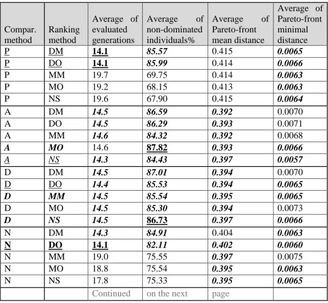
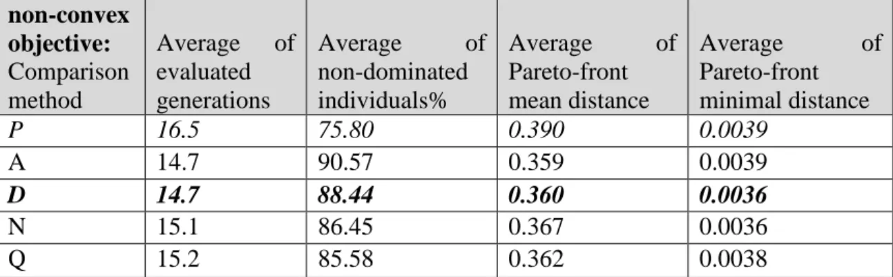
![Table II below presents the results for each tested vector comparison method – named in the first column: P as proposed in [54], A (Thesis I.c), D the classical average of weighted sum method, N (Thesis I.a), Q (Thesis I.b)](https://thumb-eu.123doks.com/thumbv2/9dokorg/514440.108/48.892.147.791.102.369/presents-results-comparison-proposed-thesis-classical-average-weighted.webp)
![Table III below presents the results for each tested ranking method named in the first column: DM (Thesis I.f), DO (Thesis I.e), MM (Thesis I.d), MO as proposed in [23], NS as proposed in [18]](https://thumb-eu.123doks.com/thumbv2/9dokorg/514440.108/49.892.147.803.755.939/presents-results-ranking-thesis-thesis-thesis-proposed-proposed.webp)