Development of Complex Curricula for Molecular Bionics and Infobionics Programs within a consortial* framework**
Consortium leader
PETER PAZMANY CATHOLIC UNIVERSITY
Consortium members
SEMMELWEIS UNIVERSITY, DIALOG CAMPUS PUBLISHER
The Project has been realised with the support of the European Union and has been co-financed by the European Social Fund ***
**Molekuláris bionika és Infobionika Szakok tananyagának komplex fejlesztése konzorciumi keretben
OF THE NERVOUS- AND NUSCULAR SYSTEM
ELECTROMYOGRAPHY (EMG)
(Az ideg- és izom-rendszer elektrofiziológiai vizsgálómódszerei )
RICHÁRD FIÁTH and GYÖRGY KARMOS
Lecture 11
(Elektromiográfia)
In this lecture the student will become familiar with the methods of
electromyography, the biological basics of the neuromuscular system, the technical basics of the EMG recording system and some examples of
neuromuscular disorders that can be diagnosed with electromyography.
Content:
Definition, subdivision and importance of electromyography
Biological basics
• The structure of the skeletal muscle
• The motor unit
• The neuromuscular junction
• Neuromuscular disorders
Technical basics
• Electrodes
• Amplifiers
DEFINITION:
Electromyography (EMG) is the recording and analysis of the bioelectric activity of skeletal muscles.
Clinical EMG is the electrodiagnostic method used for the examination of human peripheral nerves and muscles. It also includes nerve conduction studies (NCS) and reflex studies.
Other used names for EMG: electrodiagnostic examination (EDX), electroneuromyographic examination (EMNG)
IMPORTANCE OF EMG
Electromyography is an easy method, that can be carried out relatively fast, the results are reproducible, recordable and more than one muscle and nerve can be analyzed at once.
SUBDIVISIONS OF EMG
1. Conventional (clinical) electromyography 2. Macroelectromyography
3. Scanning electromyography 4. Single fiber electromyography 5. Electrical stimulation and EMG
– Nerve conduction study
– Studies with two or three stimuli
Liddell and Sherrington (end of 1920s): Defined the motor unit.
Adrian and Bronk (1929): Developed the concentric needle electrode and recorded first the sound of the electromyogram.
Denny-Brown (1929): Recorded and described first the motor unit potential.
Buchthal and Clemmens (1941): First electromyographic differentiation of neurogen and myogen muscle atrophies. They suggested the quantitative analysis of motor unit potentials.
Golseth and Fizzell (1948): Developed the first EMG device for clinical use.
Ekstedt and Stålberg (1960s): Developed the single fiber EMG method.
Stålberg (1980s): Developed the macro EMG method.
Stålberg and Antoni (1980s): Developed the scanning EMG method.
BIOLOGICAL BASICS
• The structure of the skeletal muscle
• The motor unit
• The neuromuscular junction
• Neuromuscular disorders
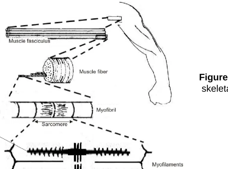
The skeletal or striated muscles are responsible for the locomotion of the body. There are more than 600 muscles in the human body. Well known muscles are for example the biceps brachii on the arm, the deltoid on the back or the quadriceps femoris on the leg. The gluteus maximus or buttock is the largest and the stapedius located in the middle ear is the smallest muscle in our body.
Muscles are anchored to the bones by tendons. The outer sheath of the muscles is called epimysium and contains the fascicles. A fascicle is a bundle of muscle fibers bounded together by the connective tissue perisymium.
Muscle fibers are surrounded by endomysium: they are the muscle cells with lost of nuclei. These muscle cells contain myofibrils which can be further divided into sarcomeres. These sarcomeres are composed of the proteins actin and myosin, which are myofilaments responsible for the contraction of the muscles. (Figure 1.)
Figure 1. Anatomy of the skeletal muscle
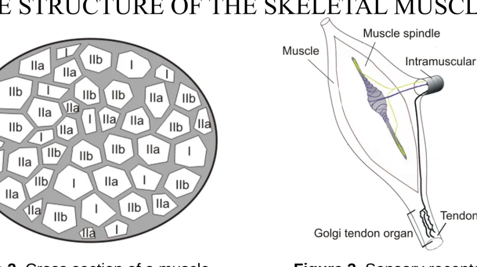
There are two types of muscle fibers: type I (slow-twitch) red and type II (fast-twitch) white fibers. Type I fibers contain more myoglobine, their contraction is slower compared to type II fibers, but the contraction holds for longer periods. Type II muscle fibers fatigue very rapidly but they are more powerful than type I fibers. Type II muscle fibers can be subdivided into two subgroups: type IIa and type IIb. (Figure 2.)
There are two types of proprioceptive sensory receptors in the skeletal muscle: muscle spindles and Golgi tendon organs. Muscle spindles are located in the belly of the muscle and detect changes in the length of the muscle. They play an important role in the stretch reflex. Golgi tendon organs can be found in the tendons near at the beginning of the muscles and are an important part of the tendon reflex. (Figure 3.)
THE STRUCTURE OF THE SKELETAL MUSCLE
Figure 2. Cross section of a muscle
fascicle. The different muscle fiber types (I,
Figure 3. Sensory receptors in the muscle: the muscle spindle and
Muscle fibers behave similar to neurons: they have a semipermeable membrane and have an electric potential difference between the extracellular and intracellular regions of the cell. This is called the resting membrane potential and has a value of about (-60 – -80) mV depending on the muscle. If a stimulus comes (an action potential reaches the axon terminal of a motor neuron and acetylcholine is exocytosed at the neuromuscular junction), the cell depolarizes and the so called end-plate potential emerges. If the end-plate potential reaches a threshold value, than an action potential is generated which advances in both directions on the muscle cell membrane and gets into the transversal tubular system. Calcium ions will be released, and after complex biochemical mechanisms the muscle contraction occurs.
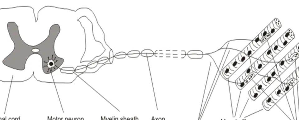
THE MOTOR UNIT (MU)
The motor unit is the smallest functional unit of the neuromuscular system that can be voluntarily activated.
Parts of the motor unit are (Figure 4.):
1. the motor neuron in the ventral horn of the spinal cord 2. the axon of the motor neuron in the peripheral nerve
3. the muscle fibers innervated by the axon terminals of the motor neuron Muscle fibers that belong to the same motor unit are placed in a mosaic
pattern, around them are fibers that are innervated by other motor units.
(Figure 5.) Electrophysiological, biochemical and histological properties of muscle fibers innervated by the same motor unit are very similar.
Figure 4. The Motor Unit
Figure 5. Muscle fibers innervated by three motor neurons. (The parts with the same color represent an individual motor unit) Muscle fibers that belong to the
The number of muscle fibers innervated by the axon of one MU is called the „innervation ratio”. There are differences between motor units in the number of innervated muscles fibers: muscles producing fine movements (like the muscles of the digits) have motor units that send axon terminals just to a few muscle fibers (10-500 fibers per MU). On the other hand the motor units of bigger muscles producing gross movements like the quadriceps femoris innervate a greater number of muscle fibers (600-2000 fibers per MU). The diameter of muscle fibers innervated by an ordinary motor unit is about 2-8 mm.
There are different type of motor units: they can be classified based on several factors like physiological, biochemical and immunohystochemical.
Somatic motor neurons which innervate the skeletal muscles can be alpha motor neurons with heavily myelinated, fast-conducting axons, that have a large diameter and innervates the muscle fibers or gamma motor neurons
RECRUITMENT OF MOTOR UNITS
The size of the motor units varies also within the same muscle. Smaller motor units have axons with smaller diameter, innervate less and smaller muscle fibers then bigger ones. These small motor units activate at first when some movement is carried out, the bigger motor units are activated during greater voluntary effort. This phenomenon is called the Henneman’s size principle.
The muscle fibers that belong to the same motor unit are contracting more or less at the same time. A slight asynchronicity can be observed due to the different length of the axon collaterals of the motor neuron (because the muscle fibers are not at equal distances), so the action potential reaches the muscle fibers (and the recording surface too) in different time delays (Figure 18.).
The neuromuscular junction is the place where the action potential of the neuron is transposed to the muscle fiber. When the action potential reaches the presynaptic motor nerve-ending (axon terminal of a motor neuron), vesicles of acetylcholine are released into the neuromuscular cleft. These activate
receptors on the muscle membrane surface, which produce miniature end-plate potentials. When the temporal summation of a burst of end-plate potentials reaches a threshold, than a muscle fiber action potential is generated which advances in both directions on the membrane and gets into the transversal tubular system, calcium ions will be released, and after complex biochemical mechanisms muscle contraction occurs. (Figure 6.)
There are four main groups of neuromuscular disorders:
• Myopathies – These are the diseases of the muscle (Muscle dystrophies, Polymyositis, Myotonia congenita)
• Neuropathies – These are diseases of motor neurons of the nervous system (Amyotrophic lateralsclerosis, Poliomyelitis)
• Diseases of the nerve fibers – Caused by the lesion (structural damage) of the motor, sensory or mixed nerves, axonal damage or demyelinisation.
• Disorders of the neuromuscular junction – Caused by the dysfunction of some structures located here (Myasthenia gravis, Eaton-Lambert syndrome, Botulism)
MYOPATHIES
Myopathy is a muscular disease, where the muscle fibers are damaged or do not function well for some reason. It results in muscle weakness. Common symptoms can be: muscle stiffness, cramps and spasm. Myopathies can be acquired or inherited.
Muscle dystrophies are a group of inherited myopathies, where the muscle cells and tissue dies and the muscles of the body are weakened. Main symptoms are poor balance, difficulty in walking, respiratory difficulty or loss of bladder control. There is no known cure for muscle dystrophies.
Polymyositis is a type of inflammatory myopathy. Major symptoms are pain, muscle weakness, loss of muscle mass in the proximal musculature.
Myotonia congenita is a genetic myopathy that affects skeletal muscles and is caused by a genetic mutation involving the chloride channel of muscles.
Delayed relaxation of the muscles, rigidity, hypertrophy, cramping and pain are the major symptoms of the disorder.
Amyotrophic lateralsclerosis (ALS) is a neurodegenerative disorder caused by the degeneration of motor neurons. Symptoms are muscle weakness, atrophy, twitching, cramping, loss of speech and difficulty of swallowing. This chronic disease cannot be cured. The end stage of ALS is called „locked in syndrome”. Stephen Hawking is the best-known person living with ALS.
Poliomyelitis or infantile paralysis, is a viral infectious disease caused by the poliovirus. The virus enters the central nervous system, destroys the motor neurons causing first muscle weakness then paralysis. Poliomyelitis is an acute disease and there is no known cure, only prevention by vaccination.
DISORDERS OF THE NEUROMUSCULAR JUNCTION
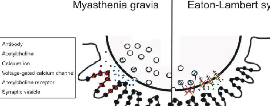
Myasthenia gravis is an autoimmune disorder caused by antibodies that block the acetylcholine receptors at the postsynaptic site of the neuromuscular junction. Symptoms are muscle weakness and fatigue. Muscles on the head are mainly affected. The treatment is with medication by giving the patient cholinesterase inhibitors or immunosuppresants or by surgical removal of the thymus. (Figure 7.)
Eaton-Lambert syndrome is also an autoimmune disease caused by the inhibition of the voltage-gated calcium channels on the presynaptic site of the neuromuscular junction. This prevents the release of acetylcholine from the presynaptic terminal, so no muscle contraction can evolve. Muscle weakness can be observed: the proximal parts of the arms and legs are mainly affected.
(Figure 7.)
Figure 7. Myasthenia gravis - Antibodies block the acetylcholine receptors therefore acetylcholine can not bind to the receptors to generate muscle contraction (left side of the figure)
Eaton-Lambert syndrome – The voltage-gated calcium channels are inhibited and the lack of calcium influx prevents the acetylcholine released from the vesicles
TECHNICAL BASICS OF EMG
• Electrodes
─ Needle electrodes
─ Surface electrodes
─ Stimulating electrodes
• Amplifiers
• Recording techniques
The concentric needle electrode consists of a stainless steel cannula, in which an insulated platinum-iridium wire is fixed by epoxy. The end of the platinum wire forms the recording surface (called different or active electrode) and the cannula serves as the reference. A concentric needle electrode which has a hemisphere radius of about 0.5 mm, can pick-up signals from about 20 muscle fibers. Used in clinical EMG. (Figure 8. A, Figure 9.)
The bipolar electrodes are constructed from a stainless steel cannula, with two platinum wires isolated from each other. Bipolar electrodes have a smaller recording surface than concentric electrodes therefore it has a greater selectivity. Used in clinical EMG. (Figure 8. B, Figure 10.)
Monopolar electrodes are stainless steel needles, coated with Teflon except for the tip of 1-3 mm. Two monopolar electrodes has to be connected to the differential amplifier at once. Can be used for stimulation or for measuring the sensory conduction velocity. (Figure 8. C)
NEEDLE ELECTRODES
Multielectrodes have small platinum contacts ( usually more than 10) on the side of the stainless steel cannula, which are the endings of the isolated platinum wires inside the cannula. Can be used for the measuring the expansion of the motor unit. (Figure 8. D)
Single fiber electrodes consist also of a stainless steel cannula, with a platinum wire inside it with a maximum of 25 micrometer in diameter and embedded in epoxy resin. The wire ends at the side of the cannula, and is exposed about 3 mm from the tip. Can be used for measuring the jitter and electrical fiber density in single fiber electromyography. The steel cannula acts as the reference electrode. The recording surface (platinum contact) picks up activity from within a hemispherical volume 300 micrometer in diameter.
Records only from 1-3 single muscle fibers innervated by the same motor unit.
(Figure 8. E)
Macroelectrodes are modified single fiber electrodes. The stainless steel cannula (about 0.5 mm in diameter) is uninsulated 15 mm from the tip. The 25 micrometer platinum wire is exposed in a sideport 7.5 mm proximal to the tip.
The cannula has two functions: first, it serves as the indifferent electrode when we record single fiber potentials and on the other hand it works as an active electrode, when recording the muscle fiber potentials near the electrode. In this case the indifferent electrode of the cannula is a conventional concentric electrode. These type of electrodes are used in macroelectromyography.
(Figure 8. F)
SURFACE ELECTRODES
Surface electrodes are made from silver/silver chloride or tin/tin lead alloy. These type of electrodes are 1-6 mm in diameter. They are used when we want to record motor units that discharge synchronously. They are useless when we want to estimate the shape and duration of single MU potentials or analyzing muscles in deeper regions. In addition, the high frequency signals are lost due to the high resistance of the tissue between the skin and the electrode. (Figure 11.)
The preparation of surface electrodes has the following way: first the skin of the subject has to be wiped with alcohol to clean the area. After that a conductive gel or electrolyte paste is used to further decrease the resistance of the skin. At last the electrode can be fixed with a bandage to the muscle to prevent unnecessary movements during muscular efforts.
Surface electrodes are used in psychophysiology or sport and ergonomic studies.
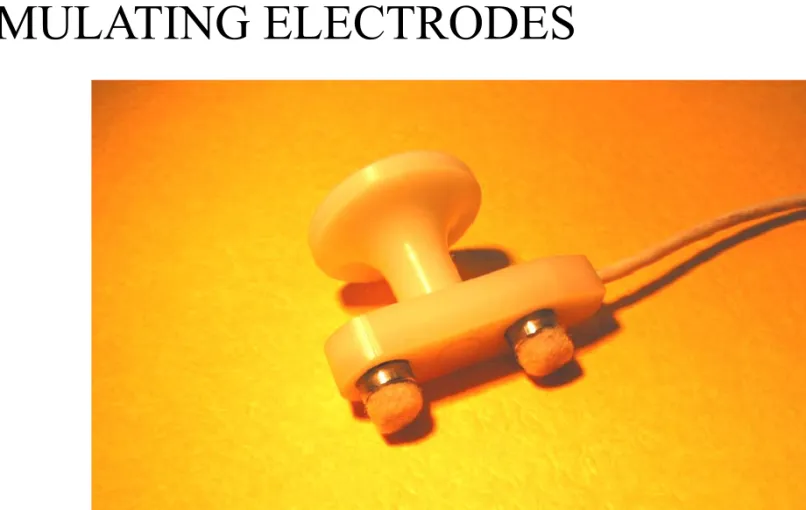
STIMULATING ELECTRODES
Stimulating electrodes can be monopolar needle electrodes, surface electrodes or ring electrodes. In case of bipolar surface electrodes with fixed interelectrode distance the distance between the anode and cathode is constant with a recommended distance of 23 mm. By plate electrodes the anode and cathode can be placed in arbitrary distances from each other. Ring electrodes are used on the fingers. They are easy to equip, but the distance between the anode and cathode is important. (Figure 12.)
GROUND ELECTRODES
Due to safety issues and to reduce stimulus artifacts the patients must be grounded. The ground electrode has to be large and should have a good contact with the skin. If stimulation is used, the grounding electrode should be placed between the stimulation and recording electrodes.
Figure 12. Stimulating electrode
ELECTRODE POTENTIAL
Electrodes are the weakest link when recording electrical signals, they are the cause of most of the noise. Electrodes are made from metal, and when a metal contacts an electrolyte (electrically conductive liquid), a potential will be developing on the contact surface, called the electrode potential. In the case of surface electrodes the electrolyte is the electrolyte paste or physiological saline and in the case of needle electrodes it is the liquor of the connective tissue. The value of the electrode potential depends on the type of metal that builds up the electrode: it is in the range from a couple millivolts to several hundred millivolts. (for a more detailed description on electrodpotential and other properties of electrodes see Lecture 5.)
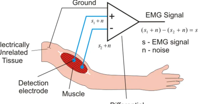
A differential amplifier is used in practice in electromyography. This has two inputs (e.g. two needle electrodes: active and indifferent), and amplifies the potential difference between this two inputs. Signals with identical phase at both electrodes will not be amplified, because the difference of this type of signals is zero (common mode rejection ratio). This means, that noise sources that are recorded on both of the two inputs (like the 50 or 60 Hz frequency of power lines) are eliminated. So it is very important, that both of the inputs have the same resistance. Therefore the resistance of the two electrodes must be also the same. In case of bipolar electrodes this is not a problem, but when concentric electrodes are used, the surface of the active and indifferent electrodes differ, so the resistance values are also different causing a greater probability of perturbation potentials. (Figure 13.)
Figure 13. Differential amplifier in case of a bipolar arrangement. Noise sources recorded on both of the inputs are eliminated, only the potential difference between
The input resistance of the amplifier has to be significantly larger, than the resistance of the electrode. Amplitude distortions can be avoided this way.
Input resistance is above 100 MΩ in modern systems.
The recorded signals are built up from different frequency components.
With filters an appropriate frequency band can be chosen to filter out the unnecessary frequency components. There are low-pass, high-pass, band-pass and band-stop filters. Usually a band-pass filter from between 20 Hz to 10 kHz is used in the amplifiers used in EMG.
After the amplification the analog signal is digitized (sampled and quantized) with an A/D converter and stored on the hard drive of a computer for subsequent analysis.
RECORDING TECHNIQUES– ARTIFACTS
In case of EMG artifacts are undesired alteration in the recorded signals that originate from other sources than the muscles being studied. Artifacts can be physiologic, mechanically induced or electrical.
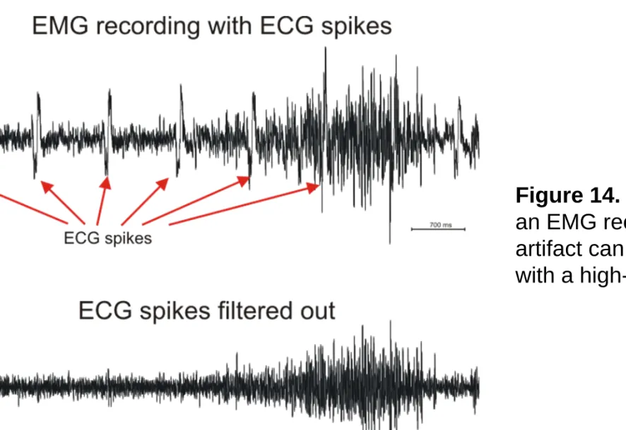
Physiologic artifacts are for example when the heart potential is recorded (ECG) or when the electrode is placed over a pulsating vessel. These appear in the recordings like rhythmic sharp waves. Sweating can produce huge slow baseline sways. (Figure 14.)
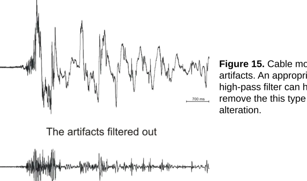
Mechanically induced artifacts can occur during cable or electrode movement. These appear as single or multiple sharp waveforms because of the impedance changes. (Figure 15.)
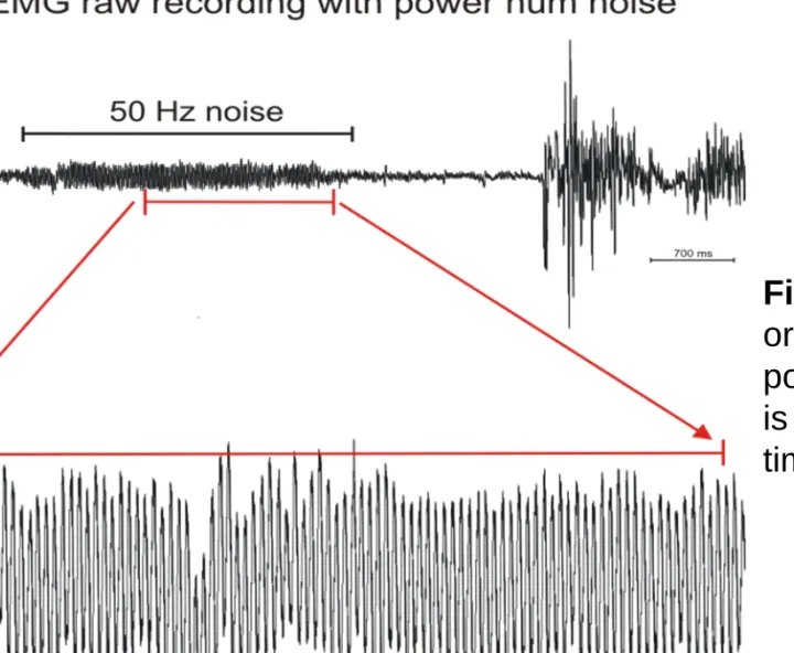
Electrical artifacts can come from electromagnetic noise sources like the 50 or 60 Hz power lines or cell phones. (Figure 16.)
Figure 14. ECG artifact on an EMG recording. The artifact can be filtered out with a high-pass filter.
Figure 15. Cable movement artifacts. An appropriate
high-pass filter can help us remove the this type of signal alteration.
Figure 16. Electrical artifact originating from the 50 Hz power lines. The noisy signal is represented in two different time scales.
RECORDING TECHNIQUES - ELECTRODE PLACEMENT
For invasive recordings the needle electrode is placed directly in the muscle belly of the muscle of interest. For surface electrodes the locations are not so obvious. A preferred location is in the region halfway between the center of the innervation zone and the further tendon. Electrodes should lie parallel to muscle fibers and the interelectrode distance should be between 2 to 10 mm. In case of bipolar recordings the contacts should have similar or the same sizes and impedances. For optimal recordings the best anatomical positions for surface electrodes have been investigated.
For surface EMG the skin of the subject has to be cleaned with an alcohol soaked gauze to lower the skin resistance. If necessary the skin should be also abraded lightly or shaved. Conductive gel is used between the electrode and the skin to further improve the quality of the recordings. The electrodes are fixed to the skin with a rubber pad and an elastic strap. (Figure 17.)
Figure 17. Electrode placement for surface EMG recordings
EMG METHODS
• Conventional (clinical) electromyography
• Macroelectromyography
• Scanning electromyography
• Single fiber electromyography
Conventional electromyographic examination is done in three steps:
1. Recording and analysis of resting muscle activity
2. Recording and analysis of different properties of the motor unit potential during gentle contraction (minimal voluntary effort)
3. Analysis of the activity patterns during maximal voluntary contraction (increasing effort)
CONVENTIONAL(CLINICAL) EMG
Conventional or clinical EMG is done with the use of surface or needle electrodes, usually with concentric needle electrodes or monopolar electrodes.
The electrode is inserted in a completely relaxed muscle, the insertion activity is recorded and analyzed whether it is normal, decreased or increased. After that, we look out for the resting activity. Every muscle chosen for analysis has to be examined in different needle positions, that means that the position and depth of the needle must be changed several times.
After that, the patient has to contract the studied muscle slightly. During the slight contraction the properties of the motor unit potentials (MUP) can be analyzed. The rule is that conclusions can be drawn only from the average of at least 20 different MUP data. Because of the size principle, only the smaller motor units can be analyzed that way.
After the MUP analysis, the patient has to do a maximal contraction, and the emerging interference pattern is analyzed.
In healthy individuals usually there is electrical silence in relaxed muscles, so electric signals observed during or after the insertion of the electrode in relaxed muscles can mean pathologic processes. Resting activity has two types: insertional activity and spontaneous activity.
Insertional activity can be divided into harm activity and end plate activity:
Harm activity is due to the mechanical injury of the muscle fibers when the needle electrode is inserted or moved. It is a high frequency (100-500 Hz), low amplitude (10-30 microvolt) spike train lasting for several seconds.
RESTING ACTIVITY
End plate activity: the needle electrode irritates the intramuscular nerve ending because the electrode is near to the end plate of the relaxed muscle.
End plate noise (low-amplitude, irregular disturbances of the baseline, miniature end plate potential activity caused by the random release of vesicles of acetylcholine at the neuromuscular junction) and end plate potential can be distinguished.
Spontaneous activity has many forms like:
Fibrillation potentials, Positive sharp waves, Fasciculations, Myokymic discharges, Myotonic discharges, Complex repetitive discharges.
The MUP is the summation of action potentials generated by the discharges of muscle fibers that are innervated by one motor unit. It can be analyzed in minimal contraction of the muscle. The needle electrode can only record a fraction of the action potentials generated by muscle fibers. It is the summation potential of 15-20 muscle fibers in a 0.5-1 mm radius.
The action potential of single muscle fibers is short in time (2-3 ms) and has a low amplitude. Muscle fibers innervated by the same motor unit are spread in all directions, and have different lengths. This two facts means that action potentials from individual muscle fibers arrives in different time moments to the recording surface (temporal dispersion), because the signal has to run different distances. The summation of these action potentials generates the 10 ms length, 200-800 microvolt MUP. (Figure 18.) Analysis of the MUP is very important in diagnostics, because important conclusions can be drawn from the changes of some of the properties of this waveform.
Figure 19. Examples of motor unit potentials in surface EMG recordings.
A – Recording from the biceps
B – Recording from the hypothenar muscles
(Recordings band-pass filtered with an analog filter from 20 Hz to 2000 Hz)
Figure 20. Motor unit potentials displayed on different timescales
Shape – The normal motor unit potential is triphasic, the beginning is positive, followed by a negative peak and ends with a slight positive deflection. The shape of the MUP changes after changing the position of the needle. The shape is influenced by factors like the distance between the electrode and the muscle fibers, the spatial position of the discharging fibers, the temperature of the muscle or the type of the electrode. No diagnostic conclusion can be drawn from the shape of the MUP.
Duration – It is the elapsed time from leaving baseline and returning to it again. The values are varying depending on the muscle, but in normal muscle it is between 5-15 ms. The more bigger is the motor unit and the more active muscle fibers are near the recording surface, the longer is the duration. The duration is pathological when it differs from the normal value by 20%.
Influencing factors are: age, temperature of the muscle, tiredness. (Figure 21.)
PROPERTIES OF THE MOTOR UNIT POTENTIAL
Amplitude – Is measured from peak to peak or from the negative peak to the baseline. The magnitude depends on the number of muscle fibers near the recording surface, and their spatial position. The action potential of the 3-4 nearest muscle fiber determines the size of the amplitude, so it can vary in the same muscle in different needle positions. The values are not the same in different muscles, it is usually 200-800 microvolts measured from peak to peak. Influencing factors: age, type of the electrode. (Figure 21.)
Rise time – Time elapsed between the first positive peak and the following negative peak. Rise time indicates the distance between the active muscle fibers and the recording surface are. (Figure 21.)
Area - Integrating the area under the MUP. The area is decreasing in myopathy caused by muscle fiber destruction.
Number of phases – The part of the MUP that is placed between the crossing of two times the baseline. If the potential crosses the baseline at least 4 times, than we call it poliphasic potential. It is caused by the desynchronicity of the muscle fiber action potentials. (Figure 21.)
Number of turns - Change of the polarity, without crossing the baseline. If more than 4 polarity change can be noticed on the potential, than it is called complex (or poliphasic) potential. It is also caused by the desynchronicity of the muscle discharges (temporal dispersion). The conduction velocity of axon terminals and muscle fibers significantly differs. (Figure 21.)
Stability - If we assume that the factors influencing the shape of the MUP are constant, than in the normal case the discharges of individual motor units coming after each other generate MUPs of the same shape and amplitude. But due to some neuromuscular disorders the MUP shape and/or amplitude can vary. This shape-change is called jiggle.
Figure 21. Properties of the motor unit potential
Figure 21. The change of the properties of motor unit potentials in
ACTIVITY PATTERNS DURING MAXIMAL CONTRACTION
The strength of the muscle contraction depends on the number of the active motor units and the discharge frequency of these. Given more strength (with increasing effort) more motor units will be activated. Smaller motor units activate first, than the bigger ones according to the size principle. This activation process is called recruitment. Parallel with the recruitment also the discharge frequency of individual motor units also increases (from 6-10 Hz to 20 Hz), the synchronization will be improved.
In normal case the so called interference pattern can be seen: the single motor unit potentials can not be separated from each other, they are interfering, so the baseline can not be recognized. So the interference pattern is the electrical activity recorded during increasing voluntary effort. (Figure 22., Figure 23., Figure 24., Figure 25.)
Figure 24. Evolved interference pattern during increasing effort by
Figure 25. Interference patterns represented on different time scales
CONTRACTION
During fatigue the amplitude of the MUP and also the discharge frequency of the motor units decreases.
When parts of the baseline remain visible and some individual motor units can still be identified during maximum voluntary effort than we talk about a
„reduced interference pattern”.
In peripheral neurogen lesion the reduced activity pattern can be seen. The number of motor units is decreased, so there is reduced recruitment. To ensure the necessary strength, the surviving motor units discharge with higher frequencies. The individual motor unit potentials can be separated and the baseline can be recognized in some parts of the recording.
ANALYZING THE EMG DATA
Steps of automatic MUP analysis gained from concentric needle electrodes:
• Collecting MUPs with a specified amplitude threshold
• Sorting these MUPs based on their shape and amplitude, clustering and comparing the clusters
• Searching for a specified number of repetitions
• Averaging of properties and statistical analysis of the identified MUPs
The automatic decomposition analysis is used for splitting the interference pattern into individual MUPs, measuring and averaging their properties with a statistical analysis at the end.
The turn/amplitude analysis is also a fast and popular method for analyzing the interference pattern. It measures the number of turns and the average amplitude difference between the turns during 1 second intervals in
Figure 26. Another analysing method is the calculation of the frequency
spectrum of the interference pattern.
Figure 27. Filtering and rectifying the interference pattern can be the basis of many automatic processing
algorithms. A few filtered and rectified sample EMG traces are represented on the figure.
FIELDS OF NONINVASIVE EMG APPLICATIONS
• Surface Mechanomyogram
• Neurology
• Ergonomics
• Exercise physiology
• Movement and gait analysis
• Rehabilitation medicine
• Biofeedback
• Control of prostheses
It is a special EMG method suitable for recording the electrical activity of the entire motor unit. Its clinical importance is in the judgment of reinnervation. The technical development was done by Stålberg.
Single fiber EMG and conventional EMG can record the electric activity only from a fraction of muscle fibers innervated by the motor units. The goal of macromyography was to a develop a method, that makes it possible to select most of the muscle fibers innervated by one analyzed motor unit with filtering out the activity of adjacent motor units, so the recorded potential would be generated mostly from one motor unit. The goal can be achieved with a modified single fiber electrode that has two recording surfaces.
The electrode makes a two-channel recording possible. With one of the channels we can record the signal of the selective single fiber electrode and with the other channel the activity of the non-selective macrosurface.
MACROELECTROMYOGRAPHY
The macroelectrode is described in the technical basics section (Figure 8.
F).
The big recording surface of the macroelectrode reaches across the whole cross-section of the motor unit, and makes possible the recording of many muscle fiber potentials. The large uninsulated part of the cannula results in a shunt effect and because of this, the distance from the needle has smaller influence on the amplitude of the recorded muscle fiber potential. A large recording surface and the shunt effect makes it possible, with the help of a special averaging technique, that only the potentials of a single motor unit will be recorded. The single fiber potential recorded on the first channel is the trigger: it controls the averaging. On the second channel we can see an average activity, which is correlated in time with the first channel, so it comes from the same motor unit. The potentials coming from the other motor units are asynchronous with the trigger, so they vanish.
The macropotential represents the spatial and temporal summation of the action potentials of the individual muscle fibers. The amplitude and area of the macropotential can grow manifold after collateral reinnervation.
The course of macromyography goes the following way:
The macroelectrode is inserted into the belly of the muscle perpendicular to the direction of the muscle fibers. The concentric electrode that acts as a reference is inserted subcutaneously far from the examined muscle. The patient is asked for a gentle contraction with constant force. After this the macroelectrode is moved into the muscle until a stable single fiber potential appears. Than an appropriate trigger level is chosen and the averaging is started. The amplitude and the area of the potential is measured. The end result of the analysis is from the median value of the macropotential data of 20 different motor units. The fiber density is also calculated in every needle position.
SCANNING ELECTROMYOGRAPHY
A method for studying the electrophysiological cross-section of the motor unit, it was developed by Stålberg and Antoni. Scanning electromyography can show the distribution of pathological malfunctions across the entire cross- section of the motor unit. The scanning EMG serves mainly scientific purposes to study the morphology of motor units and the distribution of EMG signals inside the motor units.
With scanning myographic recordings we can tell:
• The length of the cross-section of the motor unit
• The fractions of the motor unit (significant electrical activity)
• The number and length of the „silent” areas (minimal electrical activity)
• Number and length of poliphasic and complex parts
• Maximal duration and amplitude
In a healthy muscle the cross-section of motor units is between 2 and 10 mm. Throughout the cross-section 1-4 motor unit fractions can be observed, the number of „silent” areas is less then one. In case of neuropathies the maximal duration and amplitude increases together with the number of fractions and poliphasic sections. Myopathies are characterised with an increase of the silent areas, because of the destruction of muscle fibers.
The examination begins with the insertion of a concentric needle electrode (scanning electrode) into the examined muscle and afterwards it is pulled out in 50 micrometer steps with a computer controlled motor which is connected to a trigger electrode. The trigger electrode is a single fiber electrode placed 20 mm from the scanning electrode. Both electrodes have to record synchronous activity, meaning they are in the same motor unit. The electrical activity is recorded at every step until the scanning electrode is pulled of the cross-section of the motor unit. The size of the activity depends on the size of the recording
SINGLE FIBER ELECTROMYOGRAPHY (SFEMG)
The SFEMG is a selective electrophysiological method for recording the action potentials of single muscle fibers. The method was developed by Ekstedt, Stålberg and Trontelj. Physiological and morphological data can be collected this way from the muscle fibers, the motor endplate and the axon terminals. In practice, the SFEMG is used for the measure of jitter and calculation of electric fiber density. The jitter tells us about the functioning of the neuromuscular transmission, the fiber density about the muscle topography inside the motor unit. The SFEMG makes also possible the measurement of the conduction velocity of the muscle fiber action potentials, studying the discharge patterns or the using of special averaging techniques (like „spike triggering” used in macroEMG and scanning EMG methods).
The selectivity of SFEMG is achieved with a special needle electrode. The single fiber electrode is described in the technical basics section(Figure 8. E).
The recorded potential is biphasic, has an amplitude of 1-7 mV and a duration
During repetitive stimulation of the intramuscular axon it can be observed that the latency of the muscle fiber action potential recorded with a single fiber needle electrode varies from discharge to discharge. During minimal voluntary effort when the needle electrode is placed between two muscle fibers belonging to the same motor unit, two potentials are recorded. During repetitive discharging the distance between the two action potentials also changes. The time between the two action potentials is called interpotential interval (IPI). The IPI results from the different distances that the electric impulse has to achieve from the axonal bifurcation to the muscle fiber. A variability of the IPI is called jitter. This variability comes from the change of the neuromuscular transmission time, the change of the conduction time of the axon terminal and the muscle fiber.
SINGLE FIBER ELECTROMYOGRAPHY – JITTER
The jitter is increasing in diseases with the disorders of the neuromuscular transmission and in reinnervation processes. Myopathies can affect jitter in both directions: an increase can be observed in degenerating or regenerating muscle fibers and a decrease is caused by split muscle fibers.
There are two ways for measuring the jitter:
• Voluntary jitter study – Recording from two muscle fibers that belong to the same motor unit, with a voluntary contracted muscle.
• Stimulation jitter study – Recording from one muscle fiber with repetitive stimulation of that muscle.
THE FIBER DENSITY
The average of the number of potentials recorded in 20 different needle positions gives the electric fiber density of a given muscle. In a slight contraction with a healthy muscle one, two or three muscle fiber action potentials can be recorded in one needle position, so a fiber density of a healthy muscle is around 1.5. With ageing and also in neuropathies this number is increasing. In myopathies the fiber density can be higher or lower compered to the normal value.
ELECTRIC STIMULATION AND EMG
• Single pulse studies - Nerve conduction measurement
• Studies with two or three stimuli
• Repetitive stimulation
EMG studies that use single stimuli, cover the following areas:
1. Measuring the nerve conduction velocity of motor nerves:
Stimulating the nerve, recording from the muscle and analyzing the
compound muscle action potential (CMAP) or motor response (M-wave) 2. Measuring the nerve conduction velocity of sensory nerves:
Stimulating and recording from a nerve and analyzing the evoked sensory nerve action potential (SNAP)
3. Measuring the nerve conduction velocity of mixed nerves:
Stimulating and recording from a mixed nerve and analyzing the evoked mixed nerve action potential (MNAP)
4. Analysis of late waves
5. Motor unit number estimation (MUNE)
NERVE CONDUCTION STUDIES – STIMULATION PROPERTIES
Percutaneous (surface) stimulation is used with a rectangular wave (0.1 – 1 ms duration). The bipolar stimulating electrodes (Figure 12.) are placed over the nerve trunk. Both the anode and the cathode are over the nerve bundle. In deep-seated nerves or muscles surface stimulation is not possible: in this case the stimulation is carried out with needle electrodes. In motor conduction studies the recording electrode is placed over the belly of the muscle, which correlates with the endplate zone. Recommended filter settings for motor conduction studies range from10 Hz to 10 kHz and for sensory conduction studies from 20 Hz to 2 kHz.
Supramaximal stimulation means that the current or voltage intensity is slowly increased until the recorded potential is at its maximum. This intensity is used in supramaximal stimulations, while in submaximal stimulation a lower
One of the most used methods in clinical EMG. A motor or mixed nerve is stimulated with electric current at two or more places and the generated response potential (M-wave) is recorded at the most distal muscle innervated by the nerve. These muscle are called reference muscles of the respective nerve. The nerve conduction velocity can be calculated by dividing the distance between the stimulation and recording electrode with the time elapsed from the stimulation to the response potential. However the situation is not so simple.
MOTOR NERVE CONDUCTION STUDIES
For electrical stimulation there is always a supramaximal stimulus used, to stimulate all of the axons in the nerve fiber. This way the beginning of the response belongs to the latency of the fastest conducting fibers. The latency is the time elapsed from the stimulus to the appearance of the negative deflection of the response potential.
The latency consists of:
1. The „pure” conduction time
2. The terminal conduction time, where the axons are unmyelinated and the conduction speed is slower
3. The time needed for neurotransmission (slow process, 1ms)
4. The conduction time of the muscle membrane (slow process, 6 m/s)
To measure the pure conduction time that is needed for calculating the conduction velocity we have to remove the factors 2.,3. and 4. This can be managed by stimulating the nerve at two points and measuring the latency in both cases. Because the factors 2.,3. and 4. have the same values in case of both of the stimulations, if we subtract the two latencies, we get the time needed for travel the distance between the to stimulation points. After that we measure the distance between the two stimulation points and divide this value with the conduction time to get the „pure” conduction velocity. (Figure 29., Figure 30.)
The decrease of the conduction velocity can be a sign of nerve lesion. A decrease of the amplitude of the M-wave can refer to the damage of axons.
Figure 30. An example calculation of the motor nerve conduction speed (green – stimulation at the elbow, red – stimulation at the wrist )
MOTOR NERVE CONDUCTION STUDIES
Factors influencing the conduction velocity and the parameters of the response potential:
1. Temperature: cooling down decreases the conduction velocity.
2. Age: in infants the conduction velocity is 50% slower than in adults and after 20 years the conduction velocity begins slowly decreasing.
3. Conduction speed of the lower extremities is 7-10 m/s slower compared to upper extremities.
4. Incorrect measurement of the distance between the stimulation points can cause huge errors in the end results.
5. With submaximal stimulation we can measure a longer latency, because slower conducting fibers can activate first in this case.
6. Other adjacent nerves can be stimulated accidentally due to wrong
Two methods can be used:
1. Orthodrom method: follows the physiological path of the conduction of the stimulus. The nerve is stimulated distally and the recording is done proximally.
2. Antidrom method: the nerve is stimulated proximally and the answer potential is recorded distally. This method is simpler and more
advantageous for several reasons.
The latency of the sensory nerves are equal to the pure conduction time, so calculating the conduction velocity is much simpler compared to the calculation of the motor nerve conduction speed, it needs stimulation only at one place. The conduction speed of sensory nerves is 4-10% faster compared to motor nerves.
SENSORY NERVE CONDUCTION STUDIES
The conclusions are the same as by the motor nerves: decrease in the conduction velocity is a sign of demyelinisation and the decrease in the amplitude of the answer potential is the result of axonal damage.
The influencing factors are also the same as mentioned by the motor nerves.
In case of mixed nerves submaximal stimulation is used, because the threshold of sensory nerves is lower compared to motor nerves and supramaximal stimulation would activate the motor fibers and the bigger amplitude of the M-waves would hide the response potentials of sensory nerves.
After stimulating a motor or a mixed nerve by certain circumstances new response potentials emerge after the M-wave. These are called late responses or late waves. Here are some examples:
F-wave – By stimulating the motor or mixed nerves the stimulus reaches also the motor neurons in the anterior horn of the spinal cord by antidromic propagation. The action potentials of these motor neurons propagate back to the muscles orthodromically and causes a delayed contraction. (Figure 31. A)
H-wave – It is a monosynaptic reflex response originating from the spinal cord, which can be evoked by electrical stimulation. (Figure 31. B)
Figure 31. A – The generation mechanism of the F-wave
A-wave – Appears always between the M- and F-wave and develops only if the submaximal stimulus stimulates only one axon of an axon pair. The stimulus reaches the collateral branch antidromically and elicits a muscular contraction by orthodromic propagation on the other axon. (Figure 32. A) In case of supramaximal stimulation both axons are stimulated at the same time and the two antidromically propagating signals suppress each other. (Figure 32. B)
Another late wave is the Blink-reflex: a gentle hit on the forehead causes the contraction of the orbicularis oculi muscle. The reflex has two components:
the early R1 and the late R2.
Figure 32. A - The generation mechanism of the A-wave in case of submaximal stimulus B – The reason why the A-wave is absent when supramaximal stimulus is used
With the increase of the strength of the stimuli, the amplitude of the summation potential also increases. Every increase in the amplitude can indicate the activation of a new motor unit. This is the ground principle for counting the number of motor units of a given muscle. The examination is carried out with surface electrodes. The cathode is placed over the muscle belly and the anode over the tendon of the muscle. The nerve innervating the muscle is stimulated with a subthreshold stimulus increasing the intensity step by step until a response is observed. This motor unit potential is recorded and the strength of the stimulus is incremented until a higher amplitude wave appears and this new signal is recorded too. We follow this strategy until no more amplitude increase of the potential is observed. At the end, the amplitude of the compound muscle action potential (CMAP) is divided by the average difference between the amplitude changes measured earlier and we get an estimate to the number of functioning motor units.
STUDIES WITH TWO OR THREE STIMULI
Two major methods can be mentioned:
• Measuring the refractory periods of sensory nerves with two stimuli
• Collision studies
There are two types of refractory period:
• Absolute refractory period - the period immediately following a
conditioning stimulus when the nerve cannot be stimulated no matter how great test stimulus is applied (duration 0.5-1 ms)
• Relative refractory period - A period of a few milliseconds following the absolute refractory period during which the excitation threshold is raised and a much stronger test stimulus is required to initiate a response.
(duration 3-5 ms)
Measuring the refractory period of the sensory nerves is performed with applying two supramaximal stimuli to the nerve and recording the response potentials. The first is the conditioning stimulus, the second is the test stimulus. First, the amplitude and latency of the potential that emerged after applying the conditioning stimuli is measured. After this, with using double stimuli the interstimulus interval (ISI) is increased step-by-step starting from zero. The appearance of a low amplitude test potential with an elongated latency indicates the end of the absolute refractory period. The ISI that belongs to this stimulation setup is equal to the duration of the absolute refractory period. Further increasing the ISI until the amplitude and latency of the test potential is the same as that of the conditioning potential, we get the duration of the relative refractory period.
STUDIES WITH TWO OR THREE STIMULI
During the collision studies the nerves are stimulated on two locations applying two or three stimuli and changing the ISI between the stimulations.
This way the proximally generated and orthodromically propagating action potential collides with the distally evoked and antidromically propagating potential and cancel each other out.
With the collision method several examinations can be performed:
• Measuring the refractory period of motor and mixed nerves
• Eliminating the errors of motor conduction velocity measurment
• Measuring the conduction velocity of the slowest conduncting motor fibers
• Measuring the central latency of the F-wave
During repetitive stimulation a supramaximal stimulus train with defined frequency is applied on the motor and mixed nerves and the evoked motor responses are analyzed. This method is important in the diagnostics of disorders related to the neuromuscular junction. The repetitive stimulation is used with single fibre myography.
In the examinations stimulus trains with 2-3 Hz frequency consisting of 8- 10 stimuli are used. This is repeated several times and the responses are analysed, for example the amplitude and the area of the first and the fifth response is compared to measure the decrementum. After maximal contraction of the muscle either voluntary way or with 20-50 Hz stimulation, the repetitive stimulation is repeated again and the responses are compered with the data collected before the contraction to check for postactivation facilitation.
Postactivation exhaustion can be examined with repeated stimulation every minute for five minutes.
RECOMMENDED LITERATURE
• Electromyography in Clinical Practice: A Case Study Approach;
Bashar Katirji, 2007, Mosby
• Electromyography: Physiology, Engineering, and Non-Invasive Applications; Roberto Merletti, Philip Parker, 2004, IEEE Press
• Essentials of Electromoyograhy; Gary Kamen, David Gabriel, 2010, Human Kinetics
• Easy EMG; Lyn Weiss, Julie Silver, Jay Weiss, 2004, Elsevier
• More than 300 books related to EMG on http://www.amazon.com
What parts builds up a motor unit?
What are the main properties of the motor unit potential?
What is the generation mechanism of the motor unit potential?
What means the size principle?
How is the interference pattern generated?
What type of electrodes are used in EMG?
How is a differential amplifier working?
What kind of disorders are examined with EMG?
What are the main methods used in EMG?
How can we measure the motor nerve conduction speed?
What means the jitter and what means the jiggle?
What kind of EMG examinations were mentioned related to stimulation?