University of Pannonia Veszprém, Hungary
Information Science and Technology PhD School
Novel Probabilistic Methods for Visual Surveillance Applications
A thesis submitted for the degree of Doctor of Philosophy
Ákos Utasi
Supervisor: László Czúni, Ph.D.
2011
Department of Electrical Engineering and Information Systems University of Pannonia
Computer and Automation Research Institute
Hungarian Academy of Sciences
NOVEL PROBABILISTIC METHODS FOR VISUAL SURVEILLANCE APPLICATIONS
(ÚJ VALÓSZÍNŰSÉGI MÓDSZEREK VIDEÓ-MEGFIGYELÉSI ALKALMAZÁSOKHOZ)
Értekezés doktori (PhD) fokozat elnyerése érdekében Írta:
Utasi Ákos
Készült a Pannon Egyetem Informatikai Tudományok Doktori Iskolája keretében
Témavezető: Dr. Czúni László
Elfogadásra javaslom (igen / nem) ……….
(aláírás) A jelölt a doktori szigorlaton ...%-ot ért el,
Az értekezést bírálóként elfogadásra javaslom:
Bíráló neve: …... …... igen / nem
……….
(aláírás) Bíráló neve: …... …... igen / nem
……….
(aláírás)
Bíráló neve: …... …... igen / nem
……….
(aláírás) A jelölt az értekezés nyilvános vitáján …...%-ot ért el.
Veszprém, ……….
a Bíráló Bizottság elnöke A doktori (PhD) oklevél minősítése…...
………
Az EDHT elnöke
Acknowledgements
First of all I would like to give all my thanks to my parents for their constant help and support during all the years I spent with my studies.
I would like to thank my supervisor, László Czúni, for his support, help, guidance, advices and ideas during the years that led to the writing of this work. The support of University of Pannonia and the Computer and Automation Research Institute of the Hungarian Academy of Sciences (MTA-SZTAKI) is gratefully acknowledged. I say particular thanks to Prof. Tamás Szirányi, who employed me at MTA-SZTAKI after my Ph.D. studies and helped me a lot in my scientic career. Then I would like to thank my former colleagues, namely Gergely Császár, Levente Kovács, and Attila Licsár, at the Image Processing Laboratory of the Department of Image Processing and Neurocomputing, University of Pannonia, for the supportive and friendly environment they provided me in the three years of my Ph.D. studies. I thank my colleagues at the MTA-SZTAKI Distributed Events Analysis Research Group for their advice and that I could discuss all my ideas with them: Csaba Benedek, László Havasi, Anita Keszler, Ákos Kiss, Andrea Kovács, Levente Kovács and Zoltán Szlávik.
Thanks to Zsuzsanna Ürmössy for the extensive review of the grammar of my dissertation, and thanks to Csaba Beleznai for correcting the linguistic mistakes in the German abstract. I would like to thank the reviewers of my thesis for their work and valuable comments.
For further nancial supports, thanks to the Hungarian Scientic Research Fund under Grant No. 76159, the Video események szemantikus értelmezése, kategorizálása és indexelése na- tional GVOP-3.1.1.-2004-05-0388/3.0 project, and the Judicial Management by Digital Libriaries Semantics FP7 project of the EU.
Novel Probabilistic Methods for Visual Surveillance Applications
Abstract
This dissertation presents the author's results in the eld of real-time applications for visual surveillance. The methods presented here were developed with two key aspects taken into account, robustness and real-time processing capability. The presented automatic methods can be used for three dierent tasks: segmenting time-multiplexed video data, improving the performance of background-foreground separation, and detecting anomalous trac events in urban environment.
For the rst task a probabilistic model based method is presented, which achieves high speed in the segmentation of archive videos by using simple visual features. Furthermore, it can be used for detecting unusual camera and multiplexer events in online usage, such as unusual camera order or duration, manual control, and device malfunction. The presented method proved to be eective for processing both daytime and nighttime real-life recordings.
Next, the dissertation discusses a novel extension to a widely used background-foreground separation technique, which eciently reduces the incorrect detections caused by the foreground aperture problem. The proposed extension uses simple deterministic steps to eliminate the problem, and does not reduce the speed of the original method signicantly.
Finally, for the third task the author presents two dierent approaches. Instead of using object tracking, which is known to be unreliable in cluttered urban environment, both methods use the pixel-wise optical ow directions to model the usual motion patterns.
Új valószín¶ségi módszerek videó-meggyelési alkalmazásokhoz
Kivonat
A jelen disszertáció a szerz® valós idej¶ videó-meggyelési alkalmazások területén elért ered- ményeit mutatja be. Az itt bemutatásra kerül® módszerek két f® szempontot gyelembe véve lettek kifejlesztve: robusztusság és valós idej¶ feldolgozó képesség. Az elkészített automatikus eszközök három különböz® feladathoz használhatók: id®-multiplexelt videók szegmentálására, el®tér-háttér elkülönítés hatékonyságának javítására, valamint városi környezetben történ® rendhagyó forgalmi események jelzésére.
Az els® feladathoz egy valószín¶ségi modell alapú eljárás kerül bemutatásra, mely egyszer
képi jellemz®ket használva képes az archív videókat nagy sebességgel szegmentálni. A módszer ezenkívül alkalmazható rendhagyó kamera és multiplexer események valós idej¶ jelzésére is, például rendhagyó kamera sorrend és id®tartam, kézi beavatkozás és eszköz üzemzavar. A bemutatott módszer hatékonynak bizonyult mind nappali, mind éjszakai valós felvételek feldolgozása során.
A disszertáció ezután egy széles körben használt el®tér-háttér elkülönít® eljárás kiegészítését tárgyalja, mellyel hatékonyan csökkenthet® az el®tér apertúra probléma által okozott helytelen m¶ködés. A javasolt kiegészítés egyszer¶ determinisztikus lépéseket használ a probléma kiküszö- bölésére, és nem csökkenti jelent®sen az eredeti módszer sebességét.
Végül a harmadik feladathoz a szerz® két különböz® megközelítést mutat be. A zsúfolt városi környezetben megbízhatatlan objektum követés helyett a módszerek képpont szint¶ optikai áramlás irányokat használnak a tipikus mozgásminták modellezésére.
Neuartige probabilistische Methoden für visuelle Beobachtung Anwendungen
Extract
Die vorliegende Dissertation präsentiert die Ergebnisse des Autors für Echtzeitanwendun- gen der digitalen Videoüberwachung. Die vorgestellten Methoden wurden unter Berücksichtigung zweier zentraler Aspekte entwickelt: Zuverlässigkeit und Echtzeitfähigkeit bei der Verarbeitung.
Diese Methoden nden ihren Einsatz in drei verschiedenen Problemstellungen: Segmentierung von Zeit-Multiplex Video-Daten, Verbesserung der Güte von Vordergrund/Hintergrund-Trennung, und die Erkennung ungewöhnlicher Verkehrsereignisse in einer stdtischen Umgebung.
Für die erste Problemstellung wird eine probabilistische modellbasierte Methode vorgestellt, die durch Verwendung einfacher visueller Merkmale eine hohe Segmentierungsgeschwindigkeit von archivierten Videos gewährleistet. Auÿerdem kann die Methode im Online-Betrieb zur Erfas- sung ungewöhnlicher Kamera- und Multiplexer-Ereignisse, wie zum Beispiel einer ungewöhnlicher Kamera-Reihenfolge oder Einschaltdauer, einer manueller Steuerung und einer Betriebsstörung, verwendet werden. Die vorgestellte Methode erwies sich als erfolgreiches Konzept für die Verar- beitung von sowohl Tages- als auch Nachtaufnahmen in praxisrelevanten Szenen.
Als nächstes beschreibt die Dissertation eine neuartige Erweiterung für ein etabliertes Vor- dergrund/Hintergrund-Segmentierungsverfahren die fehlerhafte Detektionen verursacht durch das Vordergrund-Apertur Problem ezient reduziert. Die vorgeschlagene Erweiterung verwendet ein- fache deterministische Schritte um die Segmentierungsqualität zu verbessern ohne dabei die Rechen- geschwindigkeit zu verschlechtern.
Schlieÿlich stellt der Autor zwei unterschiedliche Ansätze für die dritte Problemstellung dar. Statt die direkte Verwendung von Objektverfolgung, die bekannterweise in Anwesenheit von Störungen und Clutter unzuverlässig wird, verwenden beide Methoden Richtungen aus pixelweise errechnetem optischen Fluss um gewöhnliche Bewegungsmuster zu modellieren.
Contents
1 Introduction 1
1.1 Commercial Products Available . . . 2
1.1.1 Surveillance Cameras . . . 2
1.1.1.1 Image Sensors . . . 2
1.1.1.2 Image Scanning Techniques . . . 4
1.1.1.3 Active Infrared Technology . . . 4
1.1.1.4 Thermal Imaging . . . 5
1.1.1.5 Lenses . . . 5
1.1.1.6 Camera Types . . . 6
1.1.2 Network Technologies . . . 7
1.1.2.1 Analog Networks . . . 8
1.1.2.2 Digital Networks . . . 8
1.1.2.3 Wireless Technology . . . 9
1.1.2.4 Video Servers . . . 9
1.1.3 Compression . . . 10
1.1.4 Smart Cameras . . . 11
1.1.5 Surveillance Systems . . . 12
1.1.5.1 Visual Management Systems . . . 13
1.2 Visual Surveillance Applications . . . 15
1.3 New Scientic Results in this Work . . . 16
1.4 Outline . . . 17
2 Mathematical Tools and Formulæ 18 2.1 Notations . . . 18
2.2 Mixture of Gaussians . . . 19
2.2.1 Parameter Estimation . . . 19
2.3 Bayes Rule . . . 20
2.4 Hidden Markov Models . . . 21
2.4.1 Discrete Density HMMs . . . 22
2.4.2 Continuous Density HMMs . . . 22
2.4.3 Viterbi Algorithm: Most Probable State Sequence . . . 23
I
2.4.4 Parameter Estimation . . . 24
2.4.5 Scaling . . . 27
2.5 Hidden Semi-Markov Models . . . 28
2.5.1 Ferguson Model . . . 29
2.5.2 Forward and Backward Variables . . . 30
2.5.3 Most Probable State Sequence . . . 32
2.5.4 Parameter Estimation . . . 32
3 Detecting Irregular Camera Events in Time-Multiplexed Videos 34 3.1 Segmenting Time-Multiplexed Videos . . . 35
3.2 Hidden Markov and Semi-Markov Models . . . 36
3.2.1 Visual Features, Observations . . . 36
3.2.2 Hidden Semi-Markov Models . . . 37
3.2.3 Model Training . . . 37
3.2.4 Oine Recognition . . . 38
3.3 Real-Time Recognition and Anomaly Detection . . . 38
3.3.1 HMM-based Detector . . . 39
3.3.2 HSMM-based Detector . . . 39
3.3.3 Anomaly Detection . . . 42
3.4 Experiments, Results . . . 43
3.4.1 Anomalous Order . . . 43
3.4.2 Unusual Duration . . . 43
3.4.3 Manual PTZ Control . . . 45
3.4.4 Device Malfunction . . . 45
3.5 Evaluation and Performance . . . 45
3.6 Conclusion . . . 47
4 Foreground-Background Separation 49 4.1 Foreground-Background Separation . . . 50
4.2 Practical Problems of Background Modeling . . . 51
4.3 Adaptive Mixture of Gaussians for Background Modeling . . . 52
4.4 Modied Mixture of Gaussians . . . 54
4.4.1 Modeling Background and Foreground . . . 54
4.4.2 Neighborhood Eects Among Foreground Pixels . . . 55
4.5 Experiments, Results . . . 56
4.6 Conclusion . . . 57
5 Unusual Event Detection in Urban Environment 58 5.1 Unusual Event Detection in Videos . . . 59
5.2 General Overview of The Proposed System . . . 62
5.2.1 Preprocessing . . . 63
5.3 Pixel-level Motion Direction Models . . . 65
II
5.3.1 Empirical Probability Estimates of Motion Direction . . . 65
5.3.2 Mixture of Gaussians by Expectation Maximization . . . 67
5.3.3 Adaptive Mixture of Gaussians . . . 67
5.3.4 Spatial Support: Segmentation of Motion Statistics . . . 68
5.3.5 Temporal Support: Markovian Extension . . . 69
5.3.6 Results, Evaluation . . . 69
5.4 Hidden Markov Models for Anomaly Detection . . . 71
5.4.1 Designating Image Regions . . . 71
5.4.2 Region-Level HMMs . . . 71
5.4.2.1 Denition and Notation . . . 72
5.4.2.2 Parameter Estimation . . . 73
5.4.2.3 Introducing Relative Emissions by Scaling . . . 73
5.4.2.4 Anomaly Detection . . . 75
5.4.3 High-Level HMMs . . . 77
5.4.3.1 Composition of High-Level HMMs . . . 78
5.4.3.2 Anomaly Detection . . . 78
5.4.4 Performance Analysis, Scope, and Limitations . . . 80
5.5 Conclusion . . . 80
6 Conclusions 82 Appendices Appendix I 84 I.1 Illustrations: Aberrations and Artifacts . . . 84
Appendix II 89 II.1 Re-estimation Using Multiple Observation Sequences . . . 89
II.2 Expectation Maximization Using Relative Emission . . . 90
Bibliography 96
Thesis Groups 101
III
List of Figures
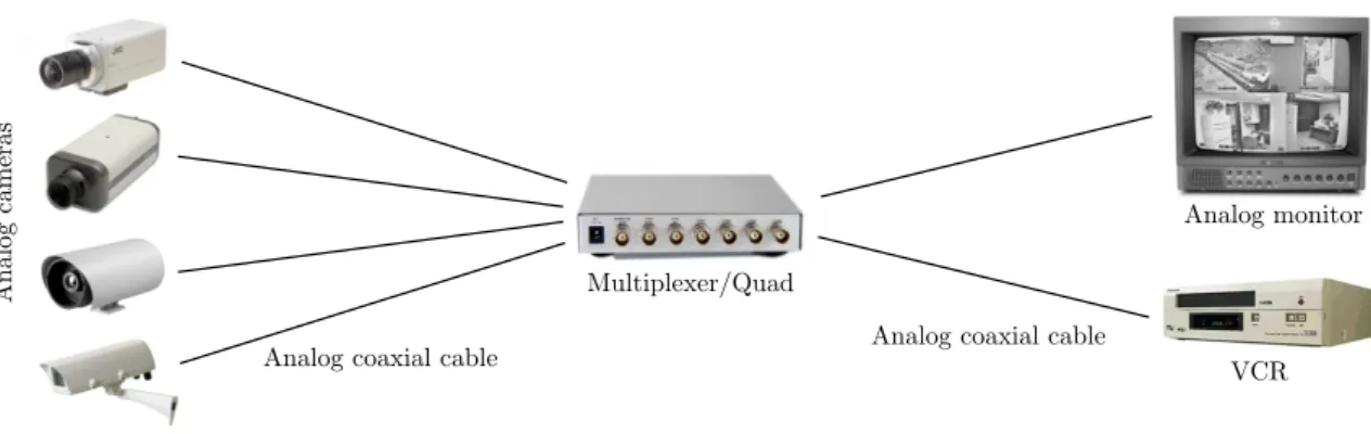
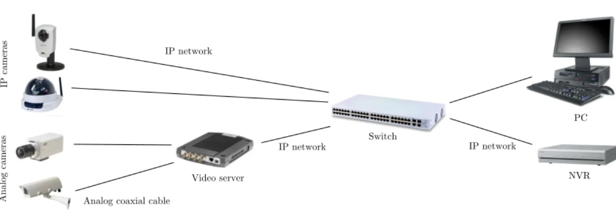
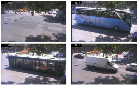
1.1 Architecture of a fully analog surveillance system. . . 13 1.2 Architecture of a partly digital surveillance system. . . 13 1.3 Architecture of a fully digital surveillance system. . . 14 3.1 Signicant changes in the visual content of the monitored outdoor scene. The four
frames were captured by the same camera at dierent times. . . 35 3.2 Observations are generated by smoothing and resizing the grayscale input video frame. 37 3.3 Oine recognition result: recognized camera positions as a function of time. The
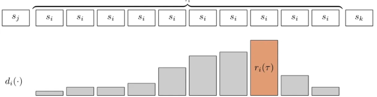
recognition rate is100%. . . 38 3.4 Denition of the maximum state durationτˆiand the remaining duration probability
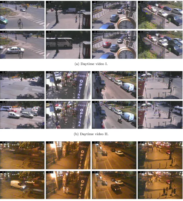
ri(τ). . . 40 3.5 Example frames from the camera scenes of the test videos we used in our experi-
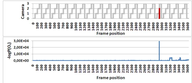
ments. The top rows contains the frames we used to initialize the models. . . 44 3.6 Anomalous camera order in Daytime video I (Fig. 3.5a) detected by HMM-based
detector. Top: detected camera sequence, unusual event marked with red color;
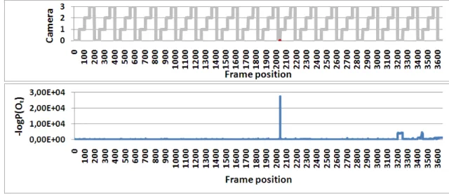
bottom: event probabilities on logarithmic scale. . . 45 3.7 The HSMM-based detector successfully detected the unusually short camera period
in the Daytime video I (Fig. 3.5a) video stream. Top: detected camera sequence (unusual event marked with red color); bottom: event probabilities on logarithmic scale. . . 46 3.8 Detecting manual PTZ control in the Daytime video I (Fig. 3.5a) using HMM-
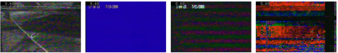
based detector. Top: detected camera sequence (unusual event marked with red color); middle: event probabilities on logarithmic scale; bottom row: example frames detected as unusual. . . 46 3.9 Example frames from video segments we used to simulate device malfunction in our
experiments. . . 47 4.1 Visual comparison of one frame from the Wallower dataset [55]. . . 56 4.2 Comparison of classical MoG-based foreground-background separation and the pro-
posed method. No morphological post-processing step was performed on the output. 57
IV
5.1 Typical practical problems of the object tracking based approaches: in (a) the tracker lost the highlighted vehicle and found another one with similar color; in (b) two vehicles were treated as a single object, after these vehicles separated the tracker found other two similar vehicles; in (c) the tracker grouped two vehicles entering the scene, but later the two cars moved in dierent directions. In our ex- periments we used a Mean Shift based tracker [13] and a Kalman [34] post-processing lter. . . 60 5.2 General architecture of the proposed system. Dashed lines denote processing steps
in the training phase only. . . 64 5.3 Typical output of the foreground-background separation using the MoG method
of [51]. . . 64 5.4 Motion vector directions are classied into eight predened direction classes. . . 65 5.5 (a) sample frame from the One-Way video; (b) pixel-wise motion direction statis-
tics; (c) Mean Shift segmented statistics; coloring is done by Eq. 5.2; (d) an object is moving against the trac in a one-way street; red overlay is used for representing the unusually moving object detected by the Mean Shift based method, this object is also marked with a yellow rectangle. . . 66 5.6 Anomaly detection results for the frames of the One-Way sequence. (a) Empir-
ical probability; (b) Mean Shift probability; (c) Mixture of Gaussians by EM; (d) Adaptive Mixture of Gaussians. Red dashed line: without Markovian extension (PUx(·|θ)). Blue solid line: with Markovian extension (PUMx (·|θ)). . . 70 5.7 (a) sample frame from the input video; (b) motion direction statistics; (c) Mean Shift
segmented statistics, coloring is done by mixing eight distinct colors proportionally to the occurrence of the motion directions as in Sec. 5.3.1; (d) moving blobs resulted by change detection, selected region is marked with red. . . 71 5.8 Probabilities of two observations by the number of test samples. In both (left and
right) examples our method converges signicantly more slowly to zero. Original emission of Eq. 5.13 is marked with yellow and the proposed relative emission of Eq. 5.15 is marked with black color. Three steps of the iterative training process are selected: initial estimate is marked with dotted, rst iteration with dashed and nal step with continuous lines. . . 75 5.9 Top: examples of the four detected states. Bottom: the state sequence of highlighted
ROI represented by the mean angles (hue) of the state MoG in HSV color space.
The rhythm of trac is clearly visible. . . 76 5.10 Experiment I. Top: Example frames detected by the low-level HMM detector.
Anomalously moving vehicle is marked with yellow contour. Bottom: the prob- ability of unusual events. The low-level detector detects the 2695th video frame as the beginning of the unusual event. . . 77
V
5.11 Experiment II. Top: Example frames detected by the low-level HMM detector.
Anomalously moving vehicle is marked with yellow contour. Bottom: the probability of unusual events. The low-level detector detects the 1681st video frame as the beginning of the unusual event. . . 77 5.12 Typical example frames for the seven states of the high-level HMM. Main directions
of the states are marked with yellow arrows while no motion state is marked with circles. . . 79 5.13 Top: Example frames detected by the high-level HMM unusual event detector.
Anomalously moving vehicle is marked with yellow contour. Bottom: the prob- ability of unusual events. The unusual event starts at the 2681th frame of the video. 79 I.1 Blooming eect: too much charge of a given pixel causes overow to pixels in its
neighborhood. . . 84 I.2 Thermal noise generated by the agitation of electrons inside the sensor. . . 84 I.3 Smear eect: vertical white stripes caused by the read out process of the CCD are
clearly visible. . . 85 I.4 Aliasing error at patterns containing high spatial frequencies. . . 85 I.5 Hot pixels are permanent and can be found in almost all image sensors. . . 85 I.6 Interlaced videos displayed on a progressive scan device. Artifacts are visible at the
location of moving objects. . . 86 I.7 Comatic aberration: beams from o-axis objects produce comet-like shapes. . . 86 I.8 Chromatic aberration: color fringes are present around the image. . . 86 I.9 (a) Barrel distortion: the straight lines bulge outwards at the center. (b) Pincushion
distortion: the aberration is the opposite of the barrel distortion. . . 87 I.10 Vignetting: (a) does not show any notable vignetting artifact, but the reduction of
brightness at the corners of (b) is signicant. . . 87 I.11 Compression artifacts: (a) blocking; (b) mosquito noise; (c) chroma subsampling
error. . . 87 I.12 Real-life outdoor recordings might contain: (a) rain and reections; (b) multiple
illumination sources, e.g. headlights; (c) cast shadow and occlusion. . . 88 I.13 Example video frames from real-life outdoor recordings demonstrating practical
problems in urban environment: (a) cluttered scenes; (b) dirt; (c) multiple illu- mination sources in nighttime videos. . . 88
VI
List of Tables
4.1 Misclassied pixels using the original MoG-based method and our extended model on the frames of Fig. 4.2. . . 57 6.1 Contributions by theses. . . 82
VII
1. Introduction 1
Chapter 1
Introduction
In the recent decade visual surveillance systems have improved rapidly, while the costs of such systems have decreased signicantly, which has made them appear on the streets of most cities or inside buildings where security is crucial, and visual surveillance has become important in several applications such as trac monitoring, license plate recognition, anomaly detection, trac jam detection, vehicle counting, crowd detection, human activity recognition. High resolution devices have appeared on the market, analog communication has given place to digital IP-based (Internet Protocol) and wireless networks, smart cameras provide built-in processors for distributed data processing, multi-camera systems have become available, and automatic storage and retrieval have become basic functions in such systems. These are just a few examples of the latest improvements by the device manufacturers. However, in most of the systems where real-time interaction is needed, human work still remains essential. The increased number of surveillance cameras produce so tremendous amounts of data that humans cannot cope with its processing, therefore automatic methods are required to substitute human work. In recent years a wide range of applications has been developed to address the problems of automatic detection and recognition in visual surveillance.
In this work we present our contribution in the eld of automatic visual surveillance. During the development of the presented methods we concentrated on two crucial aspects: robustness and real-time processing capability. Before presenting our methods, in the rest of this chapter we give a short introduction to surveillance systems. In Sec. 1.1 we present the commercially available products from the early analog devices to modern digital equipments. The device improvements and the increasing performance of computer CPUs have inuenced the development of visual
1.1. Commercial Products Available 2
surveillance applications, which are discussed in Sec. 1.2. Additionally, in these sections we discuss the practical problems and noise sources that surveillance applications have to cope with. In Appendix I we collected some example images to illustrate dierent aberrations, distortions, noise sources, and practical problems of real-life outdoor surveillance recordings.
1.1 Commercial Products Available
In this section, we briey introduce the devices mentioned above, starting from early analog equip- ments to modern wireless sensor networks and smart cameras. We start with the introduction of dierent surveillance cameras and their elements, then we give a brief discussion of the evolution of surveillance systems. Besides the brief introduction, we point out the practical problems and limitations of these devices. Our overview is limited to conventional surveillance devices, and does not include special sensor technologies (e.g. terahertz imaging, or LIDAR), which are used for special tasks, such as airport security, or military applications.
1.1.1 Surveillance Cameras
A typical surveillance camera contains an image sensor to generate a spatial, two-dimensional electronic signal from physical measurement. Most of these sensors operate in the visible spectrum, but recently other sensor types have become commercially available (e.g. thermal camera). The objective of the camera contains the lens elements, which capture the photons and focus it on the image sensor. Moreover, depending on the buildup of the objective, the camera can also provide optical zooming functionality. Most surveillance cameras oer both day and night functionality.
During the day when the illuminance level is high, the infrared light is ltered out by using an IR- cut lter to prevent unwanted color distortions. In night mode when the illuminance level is low, the IR-cut lter is removed to make use of near infrared light to deliver black and white images.
The objective is attached to the camera body, which contains the image sensor and other elements.
The body can also be attached to a base, where a small motor is used for orientation-positioning the camera. The analog and digital input/output and external synchronization interfaces are also integrated into the body.
1.1.1.1 Image Sensors
The objective of the camera focuses the light on the camera's sensor. The image sensor consists of picture elements (pixels). From the input optical image the sensor's pixels produce electronic
1.1.1.1. Image Sensors 3
signal. The two most commonly used technologies for image sensors are the CCD (charge-coupled device) and the CMOS (complementary metal-oxide semiconductor). In case of CCD sensors the charge of the pixels are transported line by line through the sensor into a charge amplier to convert the charge into voltage, which is the analog output electronic signal. Then an analog-to- digital converter turns each pixel's value into a digital number. In case of CMOS each single pixel has an integrated complementary transistor circuit which amplies the signal and assigns a digital value to it, i.e. each pixel can be accessed individually. This technology enables the integration of complex circuitry on the sensor (e.g. ampliers, noise-correction, or digitization circuits). If camera functions are implemented, each pixel can be optimized regarding e.g. brightness, range of contrast and white balance. In most single-sensor cameras a color lter array (CFA) is placed in front of the sensor's pixels to capture color information. The CFA is a mosaic of color lters in a regular pattern (e.g. Bayer lter).
The list below summarizes the practical problems of image sensors that should be considered from the image processing point of view:
• Due to the complex architecture, the light sensitivity of a CMOS chip tends to be lower than that of a CCD sensor.
• Compared to the traditional CMOS chips, the manufacturing process of a CCD sensor leads to a high quality chip in terms of light sensitivity, and CCD cameras create somewhat less noisy images than CMOS sensors.
• Smear eect: When a bright light source is present in the eld of view, a vertical white stripe appears on the image. This eect can only appear when a CCD sensor is used. The problem originates from the read out process of the sensor: the lines are shifted across the sensor to the bottom, therefore the electrical charges passing the bright light source are raised. In case of CMOS sensors the charge is read out from the pixel, hence this eect cannot appear.
• Blooming eect: In case of CCD sensors there is a limit on how much charge a pixel can store.
Too much charge can cause an overow to the neighboring pixels which is called blooming.
The overow can also spread to the neighboring elements.
• Quantization error: The sensed image is an analog signal, and an analog-to-digital converter is used to map the analog values to discrete levels. The information loss during this conversion is called quantization error.
• Aliasing error: This type of error occurs when the sampling frequency is less than twice the
1.1.1.2. Image Scanning Techniques 4
highest frequency of the signal. In digital imaging this eect becomes visible at patterns containing high spatial frequencies. In most cameras anti-aliasing lters can be found in front of the sensor to eliminate this error.
• Thermal noise: The thermal agitation of electrons in a conductor generates electronic noise, and is called thermal noise.
• Hot pixels: Almost all CCDs and CMOS chips contain sensor elements with abnormally high rate of charge leakage. As a result small bright points will appear in the image.
1.1.1.2 Image Scanning Techniques
For today's cameras two techniques are available for reading out the information from the image sensors. Interlaced scanning, mainly used in CCD sensors, produces the image from two separate elds: the rst displays the odd, the second displays the even horizontal lines. The sensor updates each eld of a video frame separately: it rst updates the odd eld, and in the next cycle the even eld. Therefore, the full frame is not available until after two cycles. In case of the progressive scan of a video the sensor progressively scans all the lines of an image, producing a full frame image at every time step.
When an interlaced video is displayed on progressive scan monitors (e.g. modern CRT or LCD computer monitors), which scan the lines of an image consecutively, the delay of the even and odd lines cause visible artifacts, for example when a fast moving target is present. Moreover, a second artifact can be noticed when the video frame contains patterns having high vertical frequency (e.g. a person's cloth containing stripes) which approach the horizontal resolution of the video format. This artifact is called interline twitter, and such patterns are twittering when displayed.
1.1.1.3 Active Infrared Technology
Ordinary CCD cameras can be combined with infrared illumination of the target to get an eective night time imaging device which operates under low illuminance levels. Near-infrared light is within the 700-1000 nm wavelength range, and although it is not visible for the human eye, it can be detected by most image sensors. Most active infrared cameras produce a monochrome image as an output. A camera that operates both in day and night conditions typically includes an IR-cut lter, which lters out the IR light in the day mode so that the colors will not get distorted.
1.1.1.4. Thermal Imaging 5
1.1.1.4 Thermal Imaging
The main disadvantage of the active infrared technology is the limited operating distance, which usually does not exceed 150 meters. Thermal imaging devices measure thermal radiation, therefore they require no active illumination. Unlike active infrared devices, thermal cameras can have a range up to 500 meters, which makes them suitable for outdoor surveillance tasks. On the other hand, the resolution of the thermal sensors is usually lower than that of ordinary image sensors.
Thermal devices are mainly used in military applications, but the price of these devices has started to drop recently, and they have become commercially available.
1.1.1.5 Lenses
The main function of the lens elements in the camera is to focus the light on the image sensor.
Besides that the lens assembly is responsible for the correct exposition by controlling the amount of light reaching the sensor. Finally, the angle of view is also dened by the lens assembly. According to the angle of view, lenses can be classied into the following classes:
• Normal lenses (25◦ -50◦): same angle of view as that of the human eye;
• Wide-angle lenses (60◦-100◦): large angle of view with good low-light performance, provides less detail than the normal lens;
• Fisheye lenses (up to180◦): extremely large angle of view;
• Telephoto lenses (10◦ -15◦): narrower angle of view, provides ne details and is used when the object is located far from the camera;
• Omnidirectional vision: captured images usually depict the full360◦angle of view (horizontal, vertical or hemispherical).
Using lenses in cameras will introduce some degree of aberration in the process of image formation.
Therefore the manufacturers design their products with care to minimize these aberrations. The list below summarizes the typical aberrations caused by the lenses.
• Spherical aberration: Lenses used in cameras usually have spherical shape, which is relatively easy to manufacture. However, light beams parallel to the optic axis of the lens but at dierent distances from the axis are focused at dierent place. In case of beams distant from the axis this eect can be signicant. The result will be a blurry image. In high quality cameras usually aspheric lenses are used to compensate the spherical aberration.
1.1.1.6. Camera Types 6
• Comatic aberration (Coma): This aberration occurs when an o-axis object is imaged. Beams passing through the outer margins of the lens are focused at a dierent position than the beams passing the center and will produce in ring-shaped patterns, also known as comatic circles. These circles form a comet-like shape.
• Chromatic aberration: Lenses focus dierent wavelengths of light to a dierent distance.
This will result in fringes of color around the image, which is most notable along sharp edges and boundaries.
• Barrel distortion: This distortion is caused by the spherical shape of the lens and deforms the whole image. The further we go from the axis the less magnication is achieved. The straight lines are rendered as curves on the image sensor and the resulting image will appear as if it was mapped around a barrel.
• Pincushion distortion: This aberration is the opposite of the barrel distortion.
• Vignetting: Vignetting is the reduction of brightness at the corners compared to the center of an image. This is usually caused by the physical size of multiple lens elements.
• Astigmatism: Rays from a point far away from the axis are not focused into one point, but form two focal lines. If an optical system with astigmatism is used to form an image of a cross, the vertical and horizontal lines will be in sharp focus at two dierent distances.
Professional camera and lens manufactures provide complex lens assemblies for correcting the various aberrations. Moreover, commercial software tools are also available for correcting dierent geometrical distortions.
1.1.1.6 Camera Types
Surveillance cameras can be categorized into the following classes.
Fixed camera: The xed camera has a lens with xed angle of view. Therefore, this category has the simplest mounting, and usually one cable is enough for the access. When they are used in outdoor environment, xed cameras can be installed in housings.
Pan-Tilt-Zoom (PTZ) camera: A PTZ camera can be controlled (pan, tilt and zoom) manually by the operator or automatically by external devices. There are two possibilities to send the control commands: over the cable used for video transmission (used for digital PTZ cameras), or by using separate serial RS-232/422/485 type wire (used for analog PTZ cameras). When the zoom factor is high, outdoor PTZ cameras are sensitive to the vibrations caused by weather conditions or by
1.1.2. Network Technologies 7
the trac (e.g. large vehicles). Therefore, several vendors implement electronic image stabilization (EIS) in the camera to reduce the eects of these vibrations. In case of PTZ cameras, the operator can program preset camera positions, which can be used in automatic patrol or guard tour mode, in which the camera visits the selected positions in sequential order.
Dome: When used in outdoor environment, xed and PTZ cameras can be installed in hous- ing, which makes them resistant to weather conditions (temperature, wind, rain, snow etc.) and vandalism and prevents them from getting sabotaged.
The following list summarizes the noise sources and problems that should be considered from the image processing point of view when using the dierent camera types.
• Outdoor scene: The outdoor scene usually contains a large number of disturbance sources, including shadows, rain, snow, clouds, dirt, and small living creatures (e.g. bugs).
• Vibrations, movements: The EIS system of the camera is limited to small movements and vibrations. Therefore, in extreme conditions (e.g. strong wind, or unstably xed housing) the EIS will fail to stabilize the image.
• Mechanical positioning: Most PTZ cameras contain mechanical parts for moving (pan and tilt) the camera. Therefore, while returning to a preset position from another one, there is always some inaccuracy present.
• Lack of position information: Most multi-camera surveillance systems transmit and store the video signal only, without any metadata (e.g. camera view change). Since most automatic machine vision methods require still images as input, surveillance applications have to apply a camera or scene change detection preprocessing step rst, otherwise the methods will not work correctly.
1.1.2 Network Technologies
Regarding the video transmission, present day cameras can be classied into two groups: analog or IP-based (digital). However, most modern surveillance systems use digital techniques to store, analyze, or annotate the camera images. Hence, the analog camera signals have to be converted to digital format. In this section we present briey the pros and cons of the two technologies, and the additional devices used for creating a network.
1.1.2.1. Analog Networks 8
1.1.2.1 Analog Networks
Most of the currently used cameras transmit the video as an analog signal, typically over BNC (coaxial) cables, that can be received by video monitors or Video Cassette Recorders (VCR).
Advantages
• Analog cameras generally cost less than IP cameras.
• Simple cabling and video signal standards that can be easily connected to most televisions or framegrabbers.
Disadvantages
• Most surveillance systems use digital data, therefore the analog signal has to be converted to digital format. This requires an analog-to-digital converter, which increases the costs of the system.
• Dicult to use in a wireless network. Other wireless devices can cause interference problems to analog systems.
• Analog cameras use an interlaced image scanning technique.
• The resolution of the transmitted video is limited by the analog encoding standard (PAL or NTSC).
1.1.2.2 Digital Networks
Recently IP camera sales have increased signicantly (36.4% growth from 2007 to 2008, while the growth of analog cameras is 6.8% in the same period), and are predicted to overtake the number of analog cameras sold by 2013 [44]. IP cameras use the Internet Protocol to transmit the video data and are equipped with Fast Ethernet link connection.
Advantages
• Existing, standardized network technologies can be used to build a camera network.
• They can be easily used with general IP networking devices, which reduces the costs of the system.
• IP cameras produce digital signals, which can be easily processed (store, analyze) by surveil- lance systems, no analog-to-digital conversion is necessary.
1.1.2.3. Wireless Technology 9
• Digital transmission requires less bandwidth than the analog one. Ecient compression techniques can be used to reduce the bandwidth consumption.
• The use of ecient compression techniques permits the transmission of high resolution videos.
• Both interlaced and progressive image scanning methods can be used.
• Image data and power can be transmitted over the same cable when using Power on Ethernet (PoE) technology.
• PTZ commands can be transmitted over the network cable.
• Wireless communication can be easily achieved by using existing standards.
• IP-based communication oers a wide range of functionalities: encryption, e-mail notication, network security, remote conguration, user authorization etc.
Disadvantages
• In general, the cost of an IP camera is higher, than that of an analog camera.
• Dierent IP cameras may use dierent encoders for video compression, which can cause compatibility problems in complex networks.
• Installation of an IP camera requires the knowledge of network protocols for proper congu- ration (e.g. IP address, routing, port forwarding).
1.1.2.3 Wireless Technology
Wireless technology provides communication without physically connecting the devices by network cable, hence it oers a exible, cost-ecient and quick way to deploy cameras. Some products have a built-in wireless adapter for easy integration into a network, but cameras without this feature can also be integrated by using a wireless bridge.
1.1.2.4 Video Servers
As already mentioned in the previous section, the signal of analog devices has to be converted to digital format for making it readable for surveillance systems. Video servers (or video encoders) enable existing analog xed or PTZ cameras to be integrated with IP-based digital networks by converting the signal from the coaxial cable of the camera into a digital video stream which can
1.1.3. Compression 10
be transmitted over an IP-based network. Video servers are usually equipped with serial RS- 232/422/485 ports for controlling analog PTZ cameras, and PoE is used to pass electrical power to the device. The servers are also responsible for forwarding the PTZ commands, sent over the Ethernet cable, to the analog cameras over the serial port, that is they enable analog PTZ cameras to be controlled over the Internet. Additionally one- or two-way audio ports and I/O ports for external devices (e.g. other sensors) can be integrated in the servers. Some vendors also provide built-in event management and intelligent video processing functions (e.g. motion detection or tampering alarm).
1.1.3 Compression
Ecient data transfer on a camera network requires video compression to reduce the size of the data by removing redundancy. By using an ecient compression technique signicant reduction can be achieved without any notable eect to the image quality. Most of the camera manufacturers use standard compression techniques to ensure compatibility. Two main compression types can be distinguished: still image and video compression. Most of the vendors support the following three compression techniques: Motion JPEG (MJPEG), MPEG-4 Part 2 (also known as MPEG- 4 Visual), MPEG-4 Part 10 (also known as ITU-T H.264, or MPEG-4 AVC). From these three formats the MPEG-4 AVC can achieve the highest data reduction rate, while the least compromis- ing the video quality. The transmitted video streams are often recompressed to dierent formats depending on the application.
High compression rate of the video data can result in visible compression artifacts. These artifacts typically originate from the quantization (color, etc.) errors, the block-based coding, or the motion compensation between video frames. The following list summarizes the most prominent artifacts, a detailed discussion can be found in [69,73].
• Blocking: Most compression techniques work with blocks (typically4×4,8×8, or16×16 pixels) instead of the whole image. This leads to the well-known artifact in compression:
borders between adjacent blocks can appear all over the images.
• Mosquito noise: The mosquito noise is a consequence of the varied coding of the same area of a scene in consecutive frames of a sequence, and is visible near the outline of sharp objects on homogeneous plain backgrounds. It appears as inappropriately-colored blotchy pattern over the object.
• Ringing: This eect can appear at sharp transitions, and is the result of the loss of high-
1.1.4. Smart Cameras 11
frequency components. The visible appearance of this eect is fake rings around strong edges.
• Subsampling error: During the compression one luminance and two chrominance channels are used, instead of the three color channels (R, G, and B). Human eye is less sensitive to color than to brightness. Hence, during video compression more chrominance than luminance information can be omitted. This technique is called chroma subsampling, and the chroma channels are stored at a lower resolution, whereas the luma channel is kept in the original form. This results in less brilliant colors in the image.
• Blurring: Most compression techniques suppress the high-frequency components of the signal by coarse quantization, which causes loss of spatial detail and a reduction of edge sharpness.
• Flicker: Image blocks are compressed with varying quantization factors over time, which can result in a visible ickering eect.
• Motion estimation error: Motion estimation is applied by modern video compression tech- niques, however only on the luminance component is used for the estimation. The resulting vectors are used for the chrominance channels, which causes mismatch.
• Aliasing error: This error can be noticed when the spatial or temporal sampling rate of the scene does not follow the Nyquist sampling theorem.
1.1.4 Smart Cameras
There is no strict denition of a smart camera, but it can be considered as an intelligent vision system that, in addition to image capturing, provides distributed local (in-camera) processing of the image data to extract application-specic features and to perform automatic event description or annotation, and alarming functionality to the end-user, thereby reducing the total amount of data transmitted through the network. Local processing may involve low and high-level image processing tasks (e.g. noise ltering, background-foreground separation, feature extraction) as well as complex machine vision tasks (e.g. object recognition and classication, activity recognition, behavior analysis). A smart camera has one image sensor in an ordinary camera housing and it includes a dedicated processor (e.g. PC architecture, or FPGA) for machine vision tasks. Addi- tionally, it may contain memory modules, digital signal processors, communication interfaces, and an operating system. Smart cameras can be extended with applications made by the manufacturer
1.1.5. Surveillance Systems 12
or by third parties. Some manufacturers also provide a full SDK for developing custom applica- tions in various programming languages. For developing smart camera applications the following limitations should be considered:
• Limited electrical power: The power coming from the power supply over the Ethernet cable is limited to maximum 15.4 W (or 25 in case of the PoE+ standard). This limitation signi- cantly restricts the number of devices (e.g. memory modules) and the computing performance of the processors used in smart cameras.
• Real-time processing: The image processing and machine vision algorithms require real-time performance. However, the processors of smart cameras have less processing power and functionalities (e.g. parallel computing) than modern PC architectures (e.g. multi-core CPU, parallel GPU) can provide.
• Constrained memory: The amount of memory of a smart camera is limited, that is storing large numbers of images and image processing results in the memory may lead to out of memory errors.
1.1.5 Surveillance Systems
Early systems used only analog techniques for communication and data storage. In the rst systems the output of the analog cameras was connected by a coaxial cable to a VCR for recording the camera images. The raw video signal was recorded on the tape without any compression. In case of multiple cameras a multiplexer or a quad was integrated into the system. The quad creates one output image from the images taken from e.g. four cameras by simply merging the downscaled images. A multiplexer takes the images from several cameras and combines them into a multiplexed video stream, which is usually performed by using time-division multiplexing (TDM) to output only one video channel at a time. A fully analog system is demonstrated in Fig. 1.1.
As a result of technical improvements, the analog VCR of the surveillance system was changed to a digital storage solution, hence partly digital systems appeared. The Digital Video Recorder (DVR) is a device capable of recording the images of analog cameras in digital format.
Instead of a videotape, DVRs use hard drives to store the video data. Therefore, the analog video signal is digitized, and then compressed to achieve ecient storage. Most DVRs have multiple video inputs and have multiplexing or quad functions integrated.
Improvements of network technology aected the surveillance systems and Network Video Recorders (NVR) have become commercially available. These devices have all the functionalities
1.1.5.1. Visual Management Systems 13
Multiplexer/Quad
Analog monitor
VCR
Analog cameras
Analog coaxial cable Analog coaxial cable
Figure 1.1: Architecture of a fully analog surveillance system.
of a traditional DVR, but they are additionally equipped with an Ethernet port for transporting the stored recordings or the live view over the IP network. Usually a custom client is provided by the manufacturer for accessing the video, but many systems can be used with standard web browsers. Fig. 1.2 demonstrates a partly digital surveillance system.
Recent technological improvements have enabled manufacturers to build fully digital surveil- lance systems. In such systems the communication is IP-based and ecient compression techniques are used for video data transmission and storage. The main advantage of a fully digital system is that standard network devices can be used to build the infrastructure and an ordinary PC can be used both for managing the camera network and for storing video recordings. Analog cameras can be easily integrated into the system by using video servers (see Sec. 1.1.2.4). Fig. 1.3 presents the architecture of a fully digital system.
1.1.5.1 Visual Management Systems
The large amount of video and audio data produced by the cameras of a modern IP-based surveil- lance network requires a video management system to store, process and retrieve/playback the data automatically. Most of these systems are either built on PC platform or by using an NVR.
Analog cameras
Analog coaxial cable
DVR
IP network IP network
Switch
PC
Figure 1.2: Architecture of a partly digital surveillance system.
1.1.5.1. Visual Management Systems 14
IP cameras IP network
Switch
PC
NVR IP network
Analog cameras
Analog coaxial cable
IP network
Video server
Figure 1.3: Architecture of a fully digital surveillance system.
PC platforms involve PC servers and other computer data storage solutions (e.g. Network-attached Storage) to achieve a high performance system. The main advantage of this approach is that it can be easily extended by additional functionalities (e.g. increased storage, device upgrade/expansion, automatic video processing, or security improvements). Hence, the system becomes fully scal- able and exible. Network video recorders have built-in management functionalities and extension is usually not allowed. The main advantage of an NVR-based management system is the easy installation process. A typical video management system has the following functionalities:
• Viewing: To provide a user interface for viewing the recorded and live video of multiple cameras. Some systems have multi-screen viewing functionalities.
• Recording: To record and store videos manually, either continuously (scheduled) or triggered by events.
• Query/retrieve: To query (e.g. by date or by event) the recorded videos and to display the query results.
• Event management: To create and identify events triggered by external entities (e.g. barcode reader, camera tampering or motion detection software). For the dierent events the sys- tem can produce dierent responses (e.g. video recording, audio/siren alarm, SMS or e-mail notication).
• Camera management: To provide a user interface for conguring the camera settings (e.g.
frame rate, resolution, compression format, or PTZ preset positions).
1.2. Visual Surveillance Applications 15
1.2 Visual Surveillance Applications
The improvements of surveillance devices has inspired the development of methods for automatic analysis of the visual data, and they are becoming essential element of modern surveillance systems.
The following list summarizes the applications of surveillance systems, including the non-complete list of functionalities that today's commercial systems can provide to the end-user.
• Transportation (highway monitoring): vehicle/pedestrian counting, speed estimation, for- bidden zone monitoring, license plate recognition, trac jam detection, wrong-way alerting, accident prevention, vehicle/pedestrian tracking, line crossing detection, vehicle tailgating, trac obstacle detection, accident alerting, abandoned vehicle warning.
• Transport hubs (e.g. airport, harbor, railway station): running human detection, crowd de- tection, crime prevention, abandoned object detection, dangerous item recognition, suspicious object detection, person tailgating.
• Public institutions (e.g. school, hospital): remote monitoring, slip and fall detection.
• Banking (nancial institution): ATM transaction monitoring, face detection, restricted area monitoring, suspicious behavior detection, detecting human entrance.
• Industrial (e.g. warehouse, factory): quality monitoring, production jam, re detection.
• Trade (retail): robbery/theft detection, loitering detection.
The manufacturers usually provide robust, stable and highly optimized algorithms for these methods. However, there are several conditions that can restrict their usability. The following list contains these usability conditions.
• Camera: most of the methods usually assume a single camera, and require xed position for the camera.
• Video: these methods require high resolution and quality, while the frame rate must be constant.
• Scene: most of these methods provide a good solution for less complex tasks, but fail with complex scenes with complex rules (e.g. crowded scenes, urban road systems, moving back- ground elements) and high occlusion rate. Moreover, nighttime recordings usually contain large number of illuminating sources (e.g. glare headlights), which makes most of the algo- rithms fail.
1.3. New Scientic Results in this Work 16
• Methodology: some methods require manual settings, ne tuning and camera calibration, while others assume preset conditions and do not adapt to the situation.
While the rst two conditions of the algorithms can easily be met by using modern high quality equipment and IP-based network, they are usually not met during the analysis of videos produced by traditional analog systems and archived data, where large amounts of noise and practical problems are present. Moreover, in an urban environment the last two conditions usually cannot be met, as the scenes are complex and the manual calibration of existing analog camera systems is dicult, costly and labor intensive. Incorrect calibration may cause faulty operation and make the intelligent functions useless, or might even result in wrong decision making. Besides these problems, in most cases intelligent surveillance tasks require real-time methods to allow immediate alarms and fast interactions. Currently the number of worldwide used digital IP cameras is still signicantly lower than the number of analog cameras [44], and a considerable proportion of the systems is said to be hybrid. As a consequence, video streams available at the monitoring oces are often multiplexed spatially or temporarily, resulting in poor spatial resolution or in unsegmented time-multiplexed videos.
1.3 New Scientic Results in this Work
As we discussed in the introduction, the processing of large amount of video data originating from multiple sources requires automatic surveillance tools to aid or substitute human work. In most cases the real-time processing capability is a mandatory condition for the application. However, the video recordings contain a signicant amount of noise originating from large numbers of dif- ferent noise sources, especially in case of outdoor scenes, and it is obvious that they cannot be completely removed in real-time. Therefore, robustness is another key attribute for automatic visual surveillance methods. All our probabilistic methods presented in this work have these two key properties and have been tested in urban scenes. We have developed novel techniques in three main elds: scene recognition in multi-camera environment, background-foreground separation for nding moving objects, and unusual event detection for nding trac anomalies.
Automatic scene recognition is a prerequisite task when the images of multiple cameras are multiplexed into one stream and the multiplexer is not synchronized with the video recorder.
Therefore, the correspondences between video segments and the dierent camera locations are unknown. Our method provides an eective solution for this task, and can be used for both oine (on archived data) and online (real-time) analysis. Our probabilistic method diers from
1.4. Outline 17
other approaches since it considers the periodicity of scenes in the multiplexed stream, the visual similarity of the images of the same scene, and the regularity and uncertainty of the segments' duration.
In background-foreground separation we examined the foreground aperture problem, which is usually not handled correctly by motion detection algorithms. We extended the most widely used adaptive mixture of Gaussians based technique with one dedicated foreground model, and dened simple rules among the foreground and background models. The numerical comparison between the original and the extended method has showed signicant decrease in the number of falsely classied pixels.
Finally, we have created a multi-level system to nd anomalous trac events in single camera videos, and included two dierent approaches to accomplish this task, both using pixel- wise optical ow information only and applying no object tracking. The rst method builds probabilistic models at each pixel, and includes temporal support to increase the dierence between normal and abnormal motion vectors, and spatial support to eliminate observation noise. The second approach constructs continuous hidden Markov models (HMM) on the noisy optical ow vectors in dierent image regions, and an anomalous event is characterized by observing unusual motion directions or unusual state changes. To solve a numerical precision problem in the model parameter estimation we have included a novel scaling technique into the mathematical formulæ of the estimation procedure. For the analysis of the state conguration of several regions, we have constructed a higher-level discrete HMM on top of several regional models. By using our system we have successfully detected dierent anomalous events, such as driving in wrong direction and crossing the red trac light at a crossroad.
1.4 Outline
After this introductory chapter, in Chapter 2 we briey present the probabilistic models we use in our methods, including the mathematical formulæ of their parameter estimation. In Chapter 3 we present the details of our time-multiplexed video segmentation and scene recognition methods by dening probabilistic detectors on the hidden Markov and semi-Markov models. In Chapter 4 the foreground aperture problem in the background-foreground separation is discussed, and we present our extension to the most widely used method to eliminate this problem. Chapter 5 presents the architecture of our unusual event detection system, and our two dierent detectors. Chapter 6 concludes our work, followed by the appendices, the bibliography and the thesis groups.
2. Mathematical Tools and Formulæ 18
Chapter 2
Mathematical Tools and Formulæ
This chapter briey introduces the statistical models and tools used in our methods. First we give the typesetting conventions of the mathematical formulæ, then we describe the statistical models and their parameter estimation procedures.
2.1 Notations
In this work the mathematical formulæ follow the conventions given below.
Variables. Variables are denoted with upper-case letter from the Latin alphabet, e.g.X,Y. In most cases the symbol is the rst letter of the variable's name. However, in some special cases we also use letters from the Greek alphabet.
Values, states. We denote the value or state of a corresponding variable in lower-case, e.g.x,y. Collections: sets, lists, sequences, and arrays. A collection of variables is denoted by bold-face upper-case letter, e.g. X = {X1, . . . , XN}. A particular assignment of value or state to each variable in the collection is denoted by bold-face lower-case letter, e.g.x={x1, . . . , xN}. Finally, a collection of collections is denoted by Calligraphy typeface, i.e.X. The elements of a set are placed in braces (i.e. {. . .}), for lists and sequences we use parentheses (i.e. (. . .)), and array elements are placed in brackets (i.e.[. . .]).
Indices. In most cases a subscript is used to reference an item in a given set, list, or array. We use the following notation:
• General indices: thei,j,k andlsymbols are used to reference an element.
• Temporal dimension: to express the temporal property of a collection thet symbol is used
2.2. Mixture of Gaussians 19
in the subscript, which takes values on the[1, T]range.
• Spatial dimension: thexandysymbols are used to reference an element in a 2-D pixel lattice of an image. Moreover, we also use the x= (x, y) notation to reference a pixel in thex, y position.
• Iteration: in iterative formulæ the iteration steps are in parentheses and appear in super- script, e.g.µ(i).
Model parameters. For the notation of model parameters we use the symbols of the Greek alphabet in most cases. Both upper and lower case letters are used, e.g.π, µ, or Σ. The set of model parameters is denoted byθ.
Probability distribution. The probability density and mass function of a distribution parame- terized by theθ set is denoted byp(x|θ), or byp(x)as a shorthand.
2.2 Mixture of Gaussians
The mixture of Gaussians model (MoG, also know as Gaussian mixture model) is a parametric probability density function represented as a weighted sum of M Gaussian components and is commonly used to model the distribution of continuous measurements (observation). The MoG is dened as
p(o) =
M
X
k=1
ωkN(o|µk, Σk) , (2.1)
where ωk are the weights, N(·|µk, Σk) denotes the normal distribution with µk mean and Σk
covariance, i.e.
N(o|µk, Σk) = 1
(2π)D/2|Σk|1/2exp
−1
2(o−µk)TΣk−1(o−µk)
, (2.2)
whereD is the dimension. Thus the MoG model is parameterized by theθ ={ωk, µk, Σk}1≤k≤M set.
2.2.1 Parameter Estimation
Letθ denote the parameters of a MoG model, i.e. it contains theωk weights, theµk means, and theΣk covariances. Leto={o1, . . . , oN} denote a particular incomplete observation sample set generated by the model, where the variables that determine the mixture component from which a
2.3. Bayes Rule 20
given observation originates are latent. The Expectation Maximization (EM) algorithm [19] can be used to compute the maximum likelihood estimates ofθgiven the observation sequenceo. The EM is an iterative method, and performs the expectation (E) step, and the maximization (M) step. The E-step computes the expected value of the log-likelihood under the current estimate of θ. In the M-step, the parameters maximizing the expected log-likelihood are computed. Finally, the new parameter estimates are used in the next E-step.
In case of a MoG model the EM has the following iterative formulæ. Let p(i)(k|n)denote the membership probability, i.e. the conditional probability of having selected the kth component given that on was observed. In the E-step of the ith iteration the membership probabilities are calculated using the current parameter estimatesθ(i)as
p(i)(k|n) =
ω(i)k N
on|µ(i)k , Σk(i)
M
P
l=1
ω(i)l N
on|µ(i)k , Σk(i) . (2.3) The membership probability values are used in the M-step to re-estimate the parameters:
ωk(i+1)= 1 N
N
X
n=1
p(i)(k|n), (2.4)
µ(i+1)k =
N
P
n=1
p(i)(k|n)on
N
P
n=1
p(i)(k|n)
, (2.5)
Σk(i+1)=
N
P
n=1
p(i)(k|n)
on−µ(i+1)k on−µ(i+1)k T N
P
n=1
p(i)(k|n)
. (2.6)
The algorithm is stopped when it has converged, i.e. when the dierence between log-likelihoods logP O|θ(i+1)andlogP O|θ(i)is suciently small. More details can be found in [19].
2.3 Bayes Rule
Most of the methods presented in this work use the Bayes rule to nd the conditional probability of a discrete random variableC(class variable) given the observation dataO. Let us assume that
2.4. Hidden Markov Models 21
Ctakes values on the nite set{c1, . . . , cN}, then by using Bayes rule we can write
P(ci|O) = P(O|ci)·P(ci)
N
P
j=1
P(O|cj)·P(cj)
=P(O|ci)·P(ci)
P(O) , (2.7)
whereP(ci) is the prior probability,P(O|ci)is the likelihood, i.e. the conditional probability of observingO given the classci, andP(ci|O) is the posterior probability, i.e. the probability ofci given thatO was observed. TheP(O)marginal probability in the denominator is a normalizing constant and is usually not evaluated. As a result the above equation simplies to
P(ci|O)∝P(O|ci)·P(ci) . (2.8) Using Eq. 2.8 we construct a classier by selecting thec?argument maximizing the posterior, i.e.
c?= argmax
ci
[P(O|ci)·P(ci)] . (2.9)
2.4 Hidden Markov Models
The name Hidden Markov Model (HMM) originates from L. P. Neuwirth, but the theoretical description of HMMs was already introduced in the late 1960s and early 1970s in the works of [25].
In this section we briey overview the theoretical background of HMMs and some related problems.
A more comprehensive tutorial on HMMs can be found in [48].
A HMM is a probabilistic model, which originates from discrete rst-order Markov processes.
LetS= {s1, . . . , sN} denote the set of N states of a system. In each t time step this system is described as being in one Qt ∈ S state, where t = 1,2, . . . , T. Between two steps the system undergoes a change of state according to a set of transition probabilities associated with each state. The transition probabilities have rst-order Markov property, i.e.
P(Qt=si|Qt−1=sj, Qt−2=sk,· · ·) =P(Qt=si|Qt−1=sj) . (2.10) Furthermore, we only consider the processes, where the Eq. 2.10 transitions are independent of time. Thus we can dene the set of transition probabilities in the form
aij =P(Qt=si|Qt−1=sj) , (2.11)
2.4.1. Discrete Density HMMs 22
where aij ≥ 0, and for a given state PN
j=1aij = 1 holds. The transition probability matrix is denoted byA={aij}1≤i,j≤N. We also dene the initial state probabilities:
πi=P(Q1=si) , (2.12)
andπ={πi}1≤i≤N. In the following part of the dissertation theiandj indices refer to a state of the HMM.
Considering the above Markov model, the states of the process are assumed to be directly observable at each instant of time. Now we extend this model to include the case, where the obser- vation is a probabilistic function of each state. Thus the underlyingQ= (Q1, . . . , QT)stochastic process (state sequence) is hidden, but it generates another observableO= (O1, . . . , OT)stochastic process (observation sequence). The emission probability (also known as output probability) of a particularotobservation for statesi is dened as
bi(ot) =P(Ot=ot|Qt=si) . (2.13) The set of all emission probabilities is denoted byB={bi(·)}1≤i≤N. The complete set of param- eters of a given HMM is described byλ= (π,A,B).
2.4.1 Discrete Density HMMs
In case of discrete HMMs we assume that the observations are symbols from a discrete V = {v1, . . . , vM}alphabet. The symbols correspond to the physical output of the system. In this case the emission probability for a givenot=vk observation is
bi(ot) =P(Ot=vk|Qt=si) . (2.14) TheBset of emission probabilities can easily be implemented as a 2-D array of size N×M.
2.4.2 Continuous Density HMMs
Many applications have to work with continuous signals, and MoG (see Sec. 2.2) is a widely used representation of the emission probability. In this work we use MoG emission probabilities only, which is dened as
bi(ot) =
M
X
l=1
ωilN(ot|µil, Σil) , (2.15)