COMPUTER AIDED DESIGNING AND MODELLING OF SPUR GEAR PAIRS HAVING NORMAL AND MODIFIED STRAIGHT TEETH
Dr. Sándor Bodzás
Ph.D., Associate Professor, Vice Head of Department, bodzassandor@eng.unideb.hu University of Debrecen, Department of Mechanical Engineering,
Debrecen, Ótemető str. 2-4., H – 4028
Abstract: The aim of this publication is to show the process of computer aided designing of the spur gear pairs having normal and modified straight teeth. For designing, the determination of the geometrical parameters is needed. Computer programs have been developed with which gear pairs having normal and modified teeth, with any arbitrary parameters can be analysed, designed and modelled. With these programs gear pairs having concrete geometry have been designed and CAD models have also been drawn to have further meshing, geometrical and TCA (Tooth Contact Analysis).
Keywords: spur gear having normal straight teeth, modified teeth, model, gear
1. INTRODUCTION
During machining of the tooth surfaces of the gear pair, tooth surfaces are cut by the tool base profile. The reference line of the tool can differ from the datum line, since the pitch circle of the gear can be rolled down not only on the datum line of the tool but any perpendicular pitch circles (Figure 1) [5, 8].
a) negative profile shift
b) positive profile shift Figure 1
Mating of the tool base profile with the tooth of the gear
x
1m
Tool datum line
Tool reference line
h
ah
ax
1m
Tool datum line Tool reference line
h
ah
aIf during cutting, the reference line of the tool does not overlap the datum line of the tool then we call it shifted cutter machining. The method can also be called ’addendum modification’ where the datum line of the tool is shifted outward the pitch circle of the generated gear wheel. The value of the shift is given as a function of the module (xm), where x is the so called profile shift coefficient. This (x) is positive if the base profile is shifted outward from the shaft, it is negative when the base profile is shifted towards the shaft [2, 5, 8]. If the profile shift coefficient is zero, then the reference line of the tool is the same as the datum line of the tool which touches the pitch circle of the gear. This wheel is called a spur gear having standard teeth [1, 2, 5, 8].
2. DESIGNING SPUR GEAR PAIR HAVING NORMAL STRAIGHT TEETH
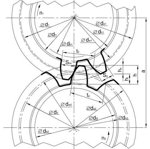
Profile shift is applied on the contact gears for designing the spur gear pair having normal straight tooth. In this case the meshing of the tooth of the mating gears is not along the pitch circle but along the working pitch circle (Figure 2) [5, 8].
Figure 2 The parameters of the spur gear pair having normal straight teeth Table 1: Main parameters of the gear pair
Notation Nomination Notation Nomination
d1, d2 Pitch circle diameter hf Dedendum
df1, df2 Root circle diameter ha Addendum
da1, da2 Tip circle diameter h Whole depth
dh1, dh2 Base circle diameter tg Circular pitch dw1, dw2 Working pitch circle diameter Sax Tooth thickness
d1 df1
da1
da2 df2 d2
dh1
dh2
db1
db2
ha hf h
Sax
n2
n1
t0 dw1
dw2
aSg
tg
c Bottom clearance m Module
hw Working depth z Number of teeth
a Centre distance js Backlash
db1, db2 Involute base circle diameter α0 Base profile angle tg Circular pitch along working pitch
circle Sg Tooth thickness along
working pitch circle
The m module is given, the z1, z2 number of teeth, α0 base profile angle and αg angle of contact. Correlations used for designing the gear pair based on Figure 2 are the following [8]:
1. Pitch circle diameters (d1, d2):
d1,2 =z1,2⋅m (1) 2. Involute base circle diameters (db1, db2):
db1,2 =d1,2⋅cos
α
0 (2) 3. Working pitch circle diameters (dw1, dw2):g b w
d d
cos
α
2 , 1 2
,
1 = (3)
4. The sum of profile shift coefficients (∑x):
0 2 0
2 1
1 2 α
α α
tg inv z inv
x z x
x g −
+ ⋅
= +
∑ = (4)
5. Centre distance (a):
2
2
1 g
g d
a d +
= (5)
6. Standard centre distance (a0):
2
2 0 1
d a d +
= (6)
7. Centre distance larger than standard (y):
m a y a− 0
= (7)
8. Mutual working depth (hw):
( )
[
x y]
mhw = 2− ∑ − ⋅ (8)
9. Addendum (ha1,2):
1,2 2
k a
h = h (9)
10. Bottom clearance (c):
m c
c= *⋅ (10) where: c* =0,25
11. Dedendum (hf1, hf2):
hf1,2 =ha1,2 +c (11) 12. Whole depth (h):
2 , 1 2 , 1 2 ,
1 ha hf
h = + (12) 13. Circular pitch (t0):
π
⋅
=m
t0 (13) 14. Circular pitch along working pitch circle (tg):
0 0
cos cos t t
g
g = ⋅
α
α (14)
15. Tip circle diameter (da1, da2):
da1,2 =d1,2 +2⋅ha1,2 (15)
16. Root circle diameter (df1, df2):
df1,2 =d1,2 −2⋅hf1,2 (16) 17. Backlash (j):
20
j = p (17)
18. The x1 profile shift coefficient:
* 1 1
1 1
1 2 2 c
m z h m
d h
x f
f g
+ +
−
−
= (18)
19. The x2 profile shift coefficient:
1
2 x x
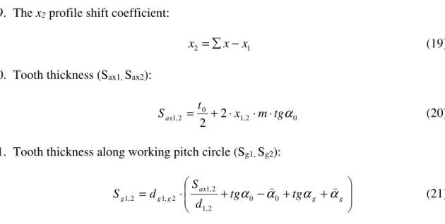
x =∑ − (19) 20. Tooth thickness (Sax1, Sax2):
0 2
, 1 0
2 ,
1 2
2 x m tgα
Sax =t + ⋅ ⋅ ⋅ (20)
21. Tooth thickness along working pitch circle (Sg1, Sg2):
+ − + +
⋅
= g g ax g g
g tg tg
d d S
S α0 α)0 α α)
2 , 1
2 , 1 2 , 1 2 ,
1 (21)
3. DESIGNING OF SPUR GEAR PAIR HAVING MODIFIED STRAIGHT TEETH The spur gear pairs having modified straight teeth are given as a borderline case when the spur gears mesh on the standard centre distance (a0) but the teeth of the gears are made by profile shift. Due to this fact the gear wheels contact along the pitch circle and the addition of the profile shift coefficient is x1+x2 =0, that is x1 =−x2. If we modify the tooth on one of the gear wheels then with the same value but with different indication you should correct the other gear wheel as well (Figure 3) [5, 8].
Figure 3 Parameters of the spur gear pair having modified straight teeth d1
df1
da1
da2
df2
a0
d2
dh1
dh2 db1
db2
ha2
hf2 h2
Sax
n2
n1
t0
hf1ha1
h1
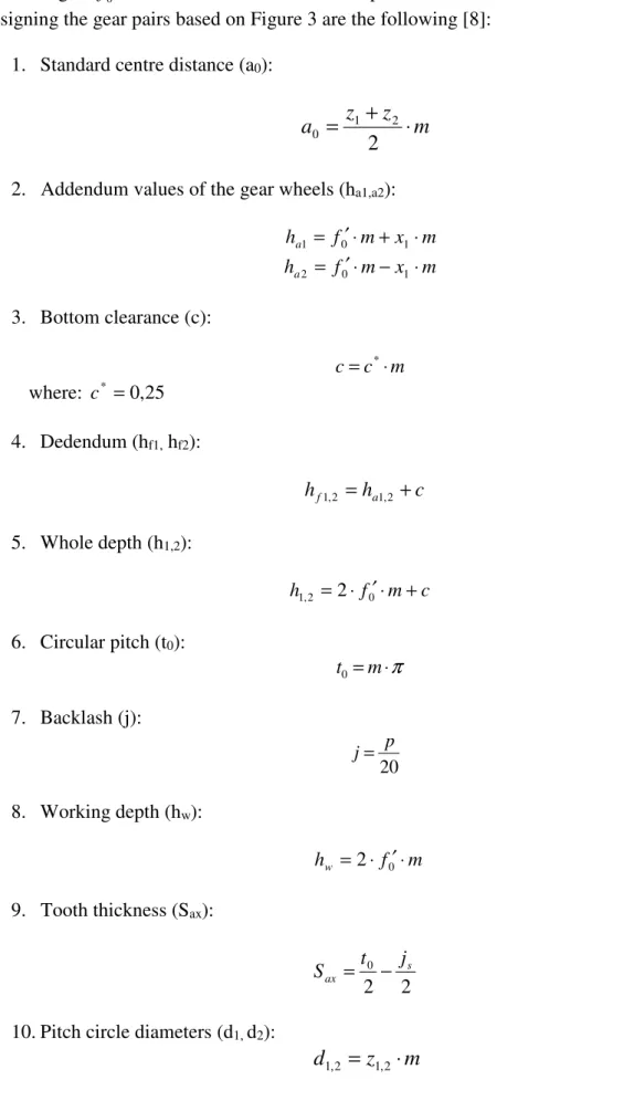
Table 1 contains the applied signs. The m module is given, z1, z2 number of teeth, α0 base profile angle, f0′ addendum coefficient, and x1 profile shift coefficient. Correlations used for designing the gear pairs based on Figure 3 are the following [8]:
1. Standard centre distance (a0):
z m a z + ⋅
= 2
2 1
0 (22)
2. Addendum values of the gear wheels (ha1,a2):
ha1 = f0′⋅m+x1⋅m
ha2 = f0′⋅m−x1⋅m (23) 3. Bottom clearance (c):
m c
c= *⋅ (24) where: c* =0,25
4. Dedendum (hf1, hf2):
hf1,2 =ha1,2 +c (25) 5. Whole depth (h1,2):
c m f
h1,2 =2⋅ 0′⋅ + (26) 6. Circular pitch (t0):
t0=m⋅π (27) 7. Backlash (j):
20
j= p (28)
8. Working depth (hw):
hw =2⋅ f0′⋅m (29) 9. Tooth thickness (Sax):
2 2
0 s
ax
j
S =t − (30)
10. Pitch circle diameters (d1, d2):
d1,2 =z1,2⋅m (31)
11. Tip circle diameters (da1, da2):
da1,2 =d1,2 +2⋅ha1,2 (32)
12. Root circle diameters (df1, df2):
df1,2 =d1,2 −2⋅hf1,2 (33) 13. Involute base circle diameter (db1, db2):
db1,2 =d1,2⋅cos
α
0 (34)4. MATHEMATICAL MODELLING
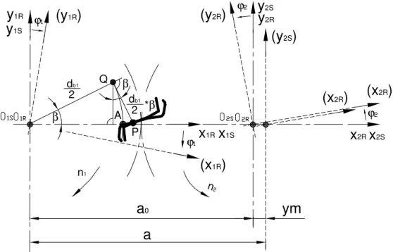
For the modelling and contact analysis of the drive pair we draw the necessary coordinate system layout (Figure 4) [1, 3, 4, 7].
Figure 4 The coordinate system used for modelling the contact analysis of the gear pair The profile of the gear pair, i.e. the equation of the involute of a circle, in K1R (x1R, y1R) coordinate system (Figure 4):
( )
(
β β β)
β β β
cos 2 sin
sin 2 cos
1 1
1 1
⋅
−
⋅
=
⋅ +
⋅
=
ak R
ak R
y d x d
(35) db1 Q
*β P A
β ϕ
ϕ
y
1R(y
1R)
x
1Sx
1Ry
2Rx
2Rn1
n2
y
2Sϕ
ϕ
x
2Sy
1S(x
1R) (y
2R)
(x
2R)
a
0β
2 db1
2
(y
2S)
(x
2R)
a
ym
We are looking for the tooth curve connected to K2R that mates with rr1R rr1R(β)
= tooth curve.
We use the fact that the 2 teeth surfaces during moving are overlapping each other and if we take into consideration the following correlation:
1 21
2 ϕ
ϕ =i ⋅ (36) then we can state that the overlapping movement can be described with a movement
parameter (φ1) [3, 4, 7]. The transformation matrix between K1R and K2R rotating coordinate systems is the following:
( )
( )
⋅
⋅
⋅ − +
⋅
−
⋅ +
⋅
⋅
⋅
−
⋅ − +
⋅
⋅
−
⋅
=
1 0
0
cos sin cos
sin sin
cos sin
cos sin
cos cos sin
sin cos
sin sin
cos cos
2 1
2 1 2
2 1
1 2
2 1
2 1 2
1 2
1 2
1 ,
2 ϕ
ϕ ϕ
ϕ ϕ
ϕ ϕ
ϕ ϕ
ϕ ϕ ϕ
ϕ ϕ
ϕ ϕ
ϕ ϕ
m y a
m y a
M R R (37)
On the tooth surfaces of the contact members, as a contact line on overlapping surfaces, it can be described by solving both the contact equation – which expresses the I. Law of Contact
2 2(12) (12) 0
) 12 ( 1
1 ⋅v =n ⋅v =n ⋅v =
nvR rR v R r R r r
(38) and the vector-scalar function - which expresses the tooth surface (Figure 4) [3, 4, 7].
The equations of the tooth surfaces of the second member, created as the overlapping surface of the contact line group in K2R coordinate system are the following[3, 4, 7]:
) 0
12 ( 1 1R⋅vR = nv r
rr1R rr1R(β)
= . (39) rr2R M2R,1R rr1R
⋅
=
Where the equation of the normal vector is:
β β
β β 2 sin 2 cos
1 1
1 1
⋅
⋅
=
⋅
⋅
=
ak R
ak R
n d n d
. (40)
5. MODELLING BY COMPUTER
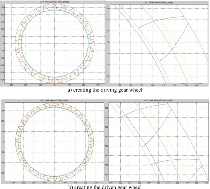
With the help of the mathematical correlations mentioned above, computer programs were developed for designing the spur gear pairs having normal and modified teeth. The program calculates the significant parameters of the drive pair (centre distance, typical circles etc.) and it draws the gear wheels. The profile points of the wheel can be saved in txt file format and can be imported into 3D engineering design software (Figure 5 and 6).
a) creating the driving gear wheel
b) creating the driven gear wheel
c) creating the CAD model
Figure 5 Modelling of spur gear pair having normal, straight teeth (m=10, z1=25, z2=35, α0=20°, αg=23°)
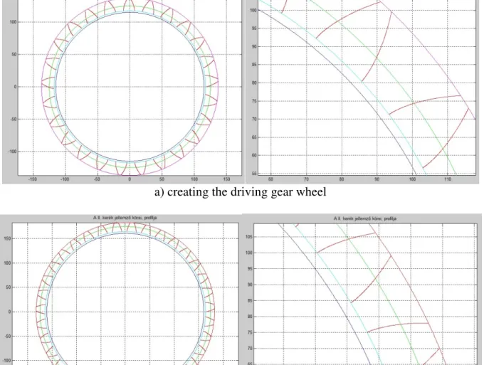
a) creating the driving gear wheel
b) creating the driven gear wheel
c) creating the CAD model
Figure 6 Modelling of the spur gear pair having modified straight teeth (m=10, z1=25, z2=35, α0=20°, f0′ =1, x1=0,2)
The interpolating, B spline surface is matched to the given profile points [6]. From the involute tooth we made body elements by extruding, which is modelled along a circumference of a given wheel appropriate for the number of teeth (Figure 5.c. and 6.c.).
SUMMARY
Geometrical correlations have been shown for designing the spur gear pairs having normal and modified straight teeth. The tooth surface of the driven gear wheel mating the driver gear has been determined by direct kinematic method.
For designing and modelling of the gear pairs computer programs have been created. The softwares calculate the dimensions of the gear pairs from the input data and they draw the model of the gear pairs.
By importing the involute profile curve points into 3D designing program and match the points with the interpolating, B spline surface, the CAD model of the drive pair has been created. This process has been applied for modelling drive pairs having concrete geometry.
With the help of our gear designing softwares - by changing the input data – any kind of geometrical spur gear pairs having standard, normal and modified straight teeth can be designed then modelled. With the use of the CAD models further contact-, geometrical- and TCA analyses can be made.
ACKNOWLEDGEMENT
This research was supported by the János Bolyai Research Scholarship of the Hungarian Academy of Sciences.
BIBLIOGRAPHY
[1] Bodzás, S.: Computer aided designing and modelling of x-zero gear drive, International Review of Applied Sciences and Engineering, Volume 8, Number 1, Akadémiai Kiadó, 2017, pp. 93-97, ISSN 2062-0810, DOI 10.1556/1848.2017.8.1.13
[2] Dudás, I.: Gépgyártástechnológia III., A. Megmunkáló eljárások és szerszámaik, B.
Fogazott alkatrészek gyártása és szerszámaik, Műszaki Kiadó, Budapest, 2011.
[3] Dudás, I.: The extension of the general mathematical model developed for helical surfaces to the whole system of manufacturing technology and production geometry (ProMAT), International Journal of Advenced Manufacturing Technology, Springer, ISSN 0268-3768 (Online), 2016. 01. 12. (Online), Volume 82, Number 1 – 4. (2016), (IF 1.458), DOI 10.1007/s00170-015-8233-5
[4] Dudás L.: Kapcsolódó felületpárok gyártásgeometriai feladatainak megoldása az elérés modell alapján, Kandidátusi értekezés, Budapest, TMB, 1991., p.144., 2005. 06. 29.
[5] Erney Gy.: Fogaskerekek, Műszaki Könyvkiadó, Budapest, 1983., p. 460.
[6] Juhász, I.: Számítógépi geometria és grafika, Miskolci Egyetemi Kiadó, Miskolc, 1993., 1995., p. 220
[7] Litvin, F. L., Fuentes, A.: Gear Geometry and Applied Theory, Cambridge University Press, 2004., ISBN 978 0 521 81517 8
[8] Terplán Z.: Gépelemek IV., Kézirat, Tankönyvkiadó, Budapest, 1975., p. 220.