Reconstruction and profile analysis of a used straight spur gear
S Bodzás1, G Balogh2
1,2University of Debrecen, Faculty of Engineering, Department of Mechanical Engineering, 4028 Debrecen, Ótemető Str. 2-4., Hungary
E-mail: bodzassandor@eng.unideb.hu
Abstract. The topic of this publication is the reconstruction and measuring process of a used straight spur gear. The tooth number, the tip circle diamater and the tooth length have to be measured for the reconstruction. Based on these parameters the type of the straight spur gear has to be determined. For the designing of the gear a new computer program is created. Based on the calculated parameters the CAD model of the gear could be designed. The profile of the real spur gear is measured by a microscope having computer controlled. The real and the theoretical involute profile curve will be analysed.
1.Introduction
The aim of the publication is the reconstruction and measuring process of a straight spur gear. In universal case a straight spur gear is given.
Figure 1. The parameters of the spur gear pair having normal straight teeth
d1 df1
da1
da2 df2 d2
dh1
dh2 db1
db2
ha hf h
Sax
n2 n1
t0 dw1
dw2
aSg
tg
The profiles are worn that is why the tooth thickness is changing and different for every tooth. The first step of the reconstruction is the determination of the standard module. The module is the basic parameter of a spur gear [2, 4, 5, 6, 7].
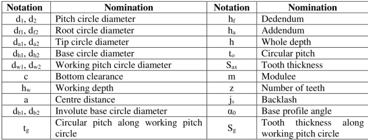
The main parameters of a connecting gear pairs could be seen on Figure 1 and Table 1.
Table 1. Main parameters of the spur gear pair
Notation Nomination Notation Nomination
d1, d2 Pitch circle diameter hf Dedendum
df1, df2 Root circle diameter ha Addendum
da1, da2 Tip circle diameter h Whole depth
dh1, dh2 Base circle diameter to Circular pitch dw1, dw2 Working pitch circle diameter Sax Tooth thickness
c Bottom clearance m Modulee
hw Working depth z Number of teeth
a Centre distance js Backlash
db1, db2 Involute base circle diameter α0 Base profile angle tg Circular pitch along working pitch
circle Sg Tooth thickness along
working pitch circle
The number of teeth could be counted. The tip circle diameter (da) of the spur gear is not worn because it is not a connecting surface. This diameter could be measured by a vernier caliper. Knowing of this dimension the module could be calculated [2, 5]:
2
The mcalc calculated module has to be rounded for the nearest and higher module (m) from the module standard [6].
a) negative profile shift b) positive profile shift Figure 2. Mating of the tool base profile with the tooth of the gear [5]
The addendum modification is given as a function of the module (xm), where x is the profile shift coefficient. This (x) is positive if the base profile is shifted outward from the shaft, it is negative when the base profile is shifted towards the shaft (Figure 2) [2, 5].
The sum of profile shift coefficients (∑x):
0 2 0
1 2
1 2 α
α α
tg inv z inv
x z x
x g
−
⋅ +
= +
∑ =
Where: α0 – base profile angle, αg – drive connection angle, which could be selected by the function of the base profile angle from the standard.
x1m
Tool datum line
Tool reference line haha x1m
Tool datum line Tool reference line
haha
(1)
(2)
The x1 profile shift coefficient:
* 1 1
1 1
1 2
2 c
m z h m
d h
x f
f g
+ +
−
−
=
The x2 profile shift coefficient:
1
2 x x
x =∑ −
The backlash between the teeth could be calculated by the following suggested formula [5]:
20 2.Calculation of the main parameters of a spur gear
After the determination of the standard module all parameters of the spur gear could be calculated by the mathematical formulas [1, 2, 5, 6, 7].
Figure 3. Creation of the mathematical model of the measured spur gear Table 2. The calculated parameters of the created spur gear
Parameter Nomination Value
Module m 1.75 mm
Number of teeth z 25
Addendum ha 1.75 mm
Clearance c 0.437 mm
Dedendum hf 2.187 mm
Circular pitch t0 5.497 mm
Backlash js 0.274 mm
Whole depth h 3.937 mm
Working depth hw 3.5 mm
Tooth thickness Sax 2.611 mm
Pitch circle diameter d0 43.75 mm Tip circle diameter da 47.25 mm Root circle diameter df 39.375 mm Basic circle diameter db 41.111 mm
(3)
(4)
(5)
A computer software was worked out to calculate the necessary parameters of a connecting gear pairs [1]. The following parameters are given: the m module, the z1, z2 number of teeth, α0 base profile angle and αg angle of contact.
The program calculates the significant parameters of the drive pair (centre distance, typical circles etc.) and it draws the spur gears. The profile points of the wheel can be saved in txt file format and it could be imported into 3 dimensional SolidWorks engineering design software. B – spline surface was fitted on the received tooth surface points [3].
The analysed spur gear having concrete geometry was created by this software (Figure 3, Table 2.).
After the calculation the computer aided model (CAD) of the spur gear was designed by SolidWorks designer software (Figure 4).
Figure 4. The CAD model of the spur gear 3.Profile measurement of the used gear
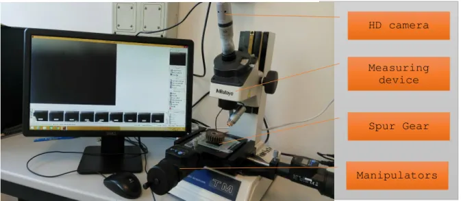
The first problem that we have to solve is to transform the measured parameters to a CAD model. We have to measure with high precision. For that reason we started the measurements on a Mitutoyo Industrial tool which is a combination of a microscope and a profile projector. We have an X-Y moveable base for the measurement with 1µm accuracy.
Originally these microscopes not fitted for digital measurement, so we have to install an HD resolution camera for the measurement. The camera was placed to the original viewing slot as it presented on the figure below (Figure 5).
Figure 5. Measuring device
HD camera
Measuring device
Manipulators Spur Gear
After we have the right measurement tool we have to create the method for rebuild the curvature of the spur gear. Our basic conception was that to create sequential images of the object with overlapping and then we can rebuild the image in really good quality and accuracy.
We have to fix the spur gear to the table we used graphite plastic for that. It’s important to avoid image processing problems because we have to handle 2070 pictures for one profile. To get the base point of the image creation process we have to define a base frame on the table. Currently we solved this with tapes. Basically we started the image creation process from the left upper corner of the imaginary matrix.
We have reset the spindles that move the tray as they are equipped with digital tripometers with µm accuracy. We determined the scale by 1 mm. This is sufficient distance to avoid being too large or too small overlap between the images to be made. We have saved the pictures numbered to make it easier and safer. Due to the size of the captured frame and the size of the scale, 45 lines and 46 columns were taken. So we thought it was expedient to use not only numbers but also have to apply letters when naming pictures. The lines are low case letters in the English alphabet, and columns are numbered.
Later there are not only one letter, but two, so the line "z" follows the "z" line, enabling the computer to simply sort the images.
These conditions make the images simple, systematizing and later assisting in the compilation. Each photo has useful resolution of 640x480 pixels. Overlapping between images in pixels is 180x135, so the useful interface that I can use for each image is the 460x345pixel. We cut this area out of each photo taken from the bottom right corner. After that, only the first and the last row or column had to be put together next to each other. The figure below represent a part of the assembly of the spur gear (Figure 6).
Figure 6. Partial image of the assembly of the spur gear profile 4.Reconstruction of used gear in CREO
Figure 7. Reconstructed 3D model of the spur gear
As a result of the measurement we get the profiles of the spur gear from both side. From this images the 3D reconstruction of the spur gear was made in CREO 3D designing system which is available at our university by the support of BOSCH group. The result of the reconstruction is represents on the figure below. At the bottom image the mass of the spur gear can see in kg. The weight of the real part
was measured later and the differences between the reconstructed and real data was 0.002 kg (Figure 7).
5.Evaluation of the measurement
After the measurement and the reconstruction process the theoretical and the reconstructed 3D model of the spur gear were fitted (Figure 8).
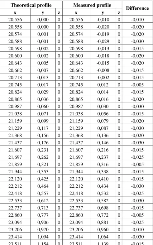
Table 3. Evaluation of one involut profile difference
Theoretical profile Measured profile
Difference
x y z x y z
20,556 0,000 0 20,556 -0,010 0 -0,010 20,558 0,000 0 20,558 -0,020 0 -0,020 20,574 0,001 0 20,574 -0,019 0 -0,020 20,588 0,001 0 20,588 -0,029 0 -0,030 20,598 0,002 0 20,598 -0,013 0 -0,015 20,600 0,002 0 20,600 -0,018 0 -0,020 20,643 0,005 0 20,643 -0,015 0 -0,020 20,662 0,007 0 20,662 -0,008 0 -0,015 20,713 0,013 0 20,713 -0,002 0 -0,015
20,745 0,017 0 20,745 0,012 0 -0,005
20,824 0,029 0 20,824 0,014 0 -0,015
20,865 0,036 0 20,865 0,016 0 -0,020
20,987 0,060 0 20,987 0,030 0 -0,030
21,038 0,071 0 21,038 0,056 0 -0,015
21,159 0,099 0 21,159 0,079 0 -0,020
21,229 0,117 0 21,229 0,087 0 -0,030
21,368 0,156 0 21,368 0,136 0 -0,020
21,437 0,176 0 21,437 0,146 0 -0,030
21,607 0,231 0 21,607 0,216 0 -0,015
21,697 0,262 0 21,697 0,237 0 -0,025
21,859 0,321 0 21,859 0,316 0 -0,005
21,944 0,353 0 21,944 0,338 0 -0,015
22,120 0,425 0 22,120 0,410 0 -0,015
22,212 0,464 0 22,212 0,434 0 -0,030
22,418 0,557 0 22,418 0,532 0 -0,025
22,533 0,612 0 22,533 0,582 0 -0,030
22,737 0,713 0 22,737 0,698 0 -0,015
22,860 0,777 0 22,860 0,772 0 -0,005
23,094 0,906 0 23,094 0,881 0 -0,025
23,206 0,970 0 23,206 0,960 0 -0,010
23,414 1,094 0 23,414 1,064 0 -0,030
23,511 1,154 0 23,511 1,139 0 -0,015
The differences between the theoretical profile and the real profile could be determined from this fitting (Figure 8, Table 3). On Table 1 one concrete profile measurement could be seen. The differences between the real and the theoretical profile was determined.
The prescribed profile tolerance is ±0,003 mm [6]. Based on this tolerance value the profile of the worn spur gear is not on the prescribed tolerance. That is why the analyzed spur gear is too worn. It could not be used further.
Figure 8. Fitting of the theoretical (grey) and the real (green) spur gear by SolidWorks software 6.Further development of measurement
The possible development of the measurement could be the multi-focus imaging, which means that we have to measure i.e. five different focus to get more complex result and more accurate image of the profile. To get the data from five layer we need to take 5x2070 images. If we want to be more accurate we have to increase this number! Because of that we have to build up an automated measuring system with motoric drive for tripometers. To solve this task and apply the image creation and processing task we have to create a complex measurement software. This could be the possible way to improve the measurement accuracy.
7.Conclusion
We had a used spur gear for the examination. Our purpose was to prepare the theoretical model of this gear and the determination of the differences between the real and the theoretical tooth profile.
If we have a used spur gear the first step is to determine the standard module. Knowing of this the calculation of the main parameters and the computer aided model (CAD) could be generated by our developed computer program.
Using of the profile microscope the profile shape of the worn tooth profile could be measured particularly. After the measurement the CAD model of the real spur gear could be generated.
Finally we could evaluate the profile differences between the real and the theoretical profile. Based on our results we could decide the other utility of the given gear by the profile standard.
The overall reconstruction and measuring process was introduced a spur gear having concrete geometry. Certainly this process is used and adapted for many type of gears.
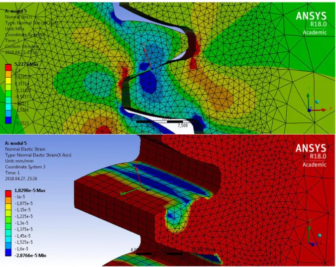
8.Tooth contact analysis researches
We do tooth contact analysis (TCA) researches for different gears in the function of the geometric parameters and the material type. We analyse the contact zone between the teeth which is established by the effect of the load.
Some results could be seen on Figure 9.
Figure 9. TCA analysis of a given geometric spur gear (m=5 mm, z1=25, z2=35) 9.References
[1] Bodzás, S., Computer aided designing and modelling of x-zero gear drive, International Review of Applied Sciences and Engineering, Volume 8, Number 1, Akadémiai Kiadó, 2017, pp.
93-97, ISSN 2062-0810, DOI 10.1556/1848.2017.8.1.13
[2] Erney, Gy., Fogaskerekek, Műszaki Könyvkiadó, Budapest, 1983., p. 460.
[3] Juhász, I., Számítógépi geometria és grafika, Miskolci Egyetemi Kiadó, Miskolc, 1993., 1995., p. 220
[4] Litvin, F. L., Fuentes, A., Gear Geometry and Applied Theory, Cambridge University Press, 2004., ISBN 978 0 521 81517 8
[5] Terplán Z., Gépelemek IV., Kézirat, Tankönyvkiadó, Budapest, 1975., p. 220.
[6] MSZ szabványgyűjtemények 91. Fogaskerékhajtások, Szabványkiadó, Budapest, 1985.
[7] Erney, Gy., A fogaskerekek mérése és gyártásellenőrzése, Műszaki Könyvkiadó, Budapest, 1959
Acknowledgement
This research was supported by the János Bolyai Research Scholarship of the Hungarian Academy of Sciences.
The work/publication is partly supported by the EFOP-3.6.1-16-2016-00022 project. The project is co-financed by the European Union and the European Social Fund.