Tooth Contact Analysis of Straight Bevel Gears in the Function of the Modification of Number of Teeth of the Driving Gear
S. Bodzás
Department of Mechanical Engineering, University of Debrecen, 4031 Debrecen, Ótemető str. 2-4., Hungary
*Email: bodzassandor@eng.unideb.hu
ABSTRACT
The bevel gear is widely used in mechanical structures if we want to change the shaft positions, the transmission ratio and the rotation direction. The aim of the publication is the analysis of the TCA (Tooth Contact Analysis) parameters in the function of the modification of the number of teeth of the driving gear. This analysis is actually a finite element analysis with which the developing normal stress, normal strain and normal deformations could be determined on the contact zone of the gear pairs. This analysis is important for the purpose of the judgment of the goodness of the gear drive. Previously the exact CAD (Computer Aided Designing) modelling of the tested gear drive is needed and after that the exact assembly is necessary. In this publication we want to determine the correlations among the TCA parameters and the number of teeth of the driven gear.
Keywords: TCA, CAD, bevel gear, number of teeth
1. INTRODUCTION
Straight bevel gears are applied widely in machinery (in vehicles, tool machines, robots, for medical tools etc.). They are used to connect shafts whose axes intersect in some angle, thus the meshing surfaces form a cone on which teeth are shaped (Figure 1, 2) [1, 2, 3, 5, 6, 7, 9, 10, 11, 12].
Figure 1. The application of straight bevel gear in case of moving of molding vat
2
Figure 2. The main parameters of bevel gear pairs
Based on Figure 2 it is visible that many parameters are needed for the exact description of the bevel gear. In case of this type the teeth are situated parallel with the rotation axis of the cone body [2, 9, 10, 11, 12].
The aim of the TCA is the analysis of the developed mechanical parameters which have to be analyzed on the gear connection. The main TCA parameters are the normal stress normal strain and normal deformation values which are determined perpendicularly to the gear surface [1, 6, 8, 9, 13].
The production cost is very expensive because of the complex geometry, the tool costs, device cost, etc. That is why the real production has to be followed after the designing, the CAD modelling and the TCA analysis.
2. DESIGNING OF GEAR PAIRS
We have worked out a computer program because of the simplification of the geometric designing process. Previously the suggestions of the references have to be read [4, 9, 10, 11, 12]. Knowing of the designing formulas the computer program could be written.
b
d02
l2
d01
l1
1
01
02
2
C Re
C
b
Re
df d0
l0 f0
f
0
l
0
0
f
E
f
dl
3
Figure 2. The profiles of bevel gear pairs on the main diameters (m=10, z1=20, z2=30)
Input data for designing the drive pair are: m module, z1 number of teeth of the driver bevel gear wheel, z2 number of teeth of the driven gear wheel, c* root clearance factor and the α0 angle of contact [4, 9, 10, 11, 12]. Knowing of them the program is calculated all necessary geometric parameters of the gear pairs and drawn the profile curves on the highest and the lowest diameters (Figure 2).
a) z1=20 b) z1=21 c) z1=22
d) z1=23 e) z1=24 Figure 3. The type of the CAD models of the designed gears
4
After the geometric calculation the CAD models of the bevel gears could be created by SolidWorks software (Figure 3). Interpolation B-spline has to be fit on the profile points.
Knowing of the necessary profile curves the teeth could be created by extrusion.
Table 1. The calculated parameters of the designed bevel gear pairs
The main parameters of the bevel gear pairs
Gear drive I.
Gear drive II.
Gear drive III.
Gear drive IV.
Gear drive V.
Number of teeth of the driving gear (z1) 20 21 22 23 24
Number of teeth of the driven gear (z2) 30
Module (m) [mm] 10
The largest pitch circle diameter of the driving gear (d01) [mm]
200 210 220 230 240
The largest pitch circle diameter of the driving gear (d02) [mm]
300 Half pitch angle of the pitch circle of the
driving gear (𝛿01) [°]
56.309 55.008 53.746 52.523 51.340 Half pitch angle of the pitch circle of the
driven gear (𝛿02) [°]
33.69 34.992 36.253 37.476 38.659 Effective pitch surface radius (Re) [mm] 180.277 183.098 186.01 189.01 192.093 Addendum on the largest diameter (f0) [mm] 10
Dedendum on the largest diameter (l0) [mm] 12 The largest tip circle diameter of the
driving gear (df1) [mm]
211.094 221.469 231.827 242.168 252.493 The largest tip circle diameter of the
driven gear (df2) [mm]
316.641 316.384 316.128 315.872 315.617 The largest root circle diameter of the
driving gear (da1) [mm]
186.687 196.236 205.807 215.397 225.007 The largest root circle diameter of the driven
gear (da2) [mm]
280.03 280.338 280.646 280.953 281.259
Face width (b) [mm] 51.507 52.313 53.145 54.003 54.883
Dedendum angle (λ) [°] 3.808 3.749 3.691 3.632 3.574
Tip cone angle of the driving gear (𝛿𝑓1) [°] 60.118 58.757 57.437 56.156 54.914 Tip cone angle of the driven gear (𝛿𝑓2) [°] 37.498 38.741 39.945 41.108 42.234 Root cone angle of the driving gear (𝛿𝑙1) [°] 52.501 51.258 50.055 48.891 47.765 Root cone angle of the driven gear (𝛿𝑙2) [°] 29.881 31.242 32.562 33.843 35.085 Circular pitch on the largest pitch circle
diameter (t) [mm]
31.415
Clearance at flank (js) [mm] 1.570
Pitch circle tooth thickness on the largest diameters (Sax) [mm]
17.278
Transmission ratio (i) 1.5 1.428 1.363 1.304 1.25
5
On Table 1 the calculated parameters of the bevel gears could be seen. After the geometric designing the TCA could be followed.
3. TCA ANALYSIS OF CONNECTING BEVEL GEAR PAIRS 3.1. The adoption of the finite element mesh
The appropriate selection of the finite element mesh is the basis of the calculation process [8, 13]. One of the main property of the bevel gear is the teeth are continuously narrows from the highest cone’s diameters to the lowest cone’s diameters. Because of this property the equable mesh subdivision could not be applied.
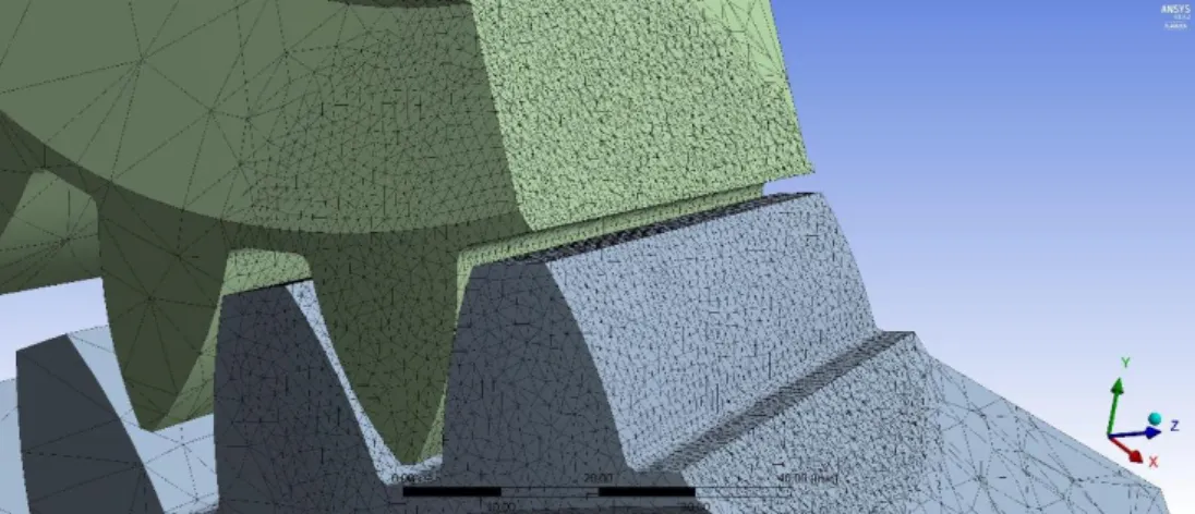
We have adopted a coordinate system in the middle of the teeth connection zone (Figure 4).
Figure 4. The adoption of the coordinate system into the middle of the connection zone
The x axis of the adopted coordinate system is shown into the normal direction of the connecting surfaces (Figure 4).
Sphere of influence meshing has been applied on the contact zone. The mesh shape is dense triangles. The density is 1.5 mm and the sphere radius is 38 mm. Automatic meshing has been applied in the outside of the contact zone (Figure 5).
Figure 5. The adoption of the finite element mesh The type of the applied material has been structural steel (Table 2).
6
Table 2. The properties of the applied material
Density 7850 kg/m3
Yield limit 250 MPa
Ultimate strength 460 MPa
The driving bevel gear has been loaded by 600 Nm moment. Five degrees of freedom have been fixed on the driving gear only the turning motion around the axis of rotation has been let. The driven gear has been totally fixed.
3.2. Analysis of the normal stress
The normal stress is interpreted on perpendicular direction of the tooth surface [8, 9, 13].
These direction is the most determinative in aspect of tooth deformation. This normal stress has been calculated for the tooth contact zone (Figure 6).
Driving gear Driven gear
𝜎𝑛
̅̅̅ = −5.753 MPa 𝜎̅̅̅ = −6.104 MPa 𝑛 z1=20
𝜎𝑛
̅̅̅ = −5.888 MPa 𝜎̅̅̅ = −4.417 MPa 𝑛 z1=21
𝜎𝑛
̅̅̅ = −5.075 MPa 𝜎̅̅̅ = −4.906 MPa 𝑛 z1=22
7 𝜎𝑛
̅̅̅ = −4.267 MPa 𝜎̅̅̅ = −5.125 MPa 𝑛 z1=23
𝜎𝑛
̅̅̅ = −4.035 MPa 𝜎̅̅̅ = −5.043 MPa 𝑛 z1=24
Figure 6. Normal stress results for every bevel gear pairs
Based on the calculations the normal stresses could be seen in the function of the number of teeth of the driving bevel gear on Figure 7.
Based on the results the minimum normal stress of the surface of the driving bevel gear is developed in case of z1=24 number of teeth in absolute value. The minimum normal stress of the surface of the driven bevel gear is developed in case of z1=21 number of teeth in absolute value (Figure 7).
a) driving bevel gear -5,753
-5,888 -5,075
-4,267 -4,035
-6,5 -6 -5,5 -5 -4,5 -4 -3,5
19 20 21 22 23 24 25
Normal stress (MPa)
Number of teeth of the driving gear
Number of teeth of the driving gear - Normal stress (driving gear)
8
b) driven bevel gear
Figure 7. The developed normal stresses in the function of the number of teeth 3.3. Analysis of the normal elastic strain
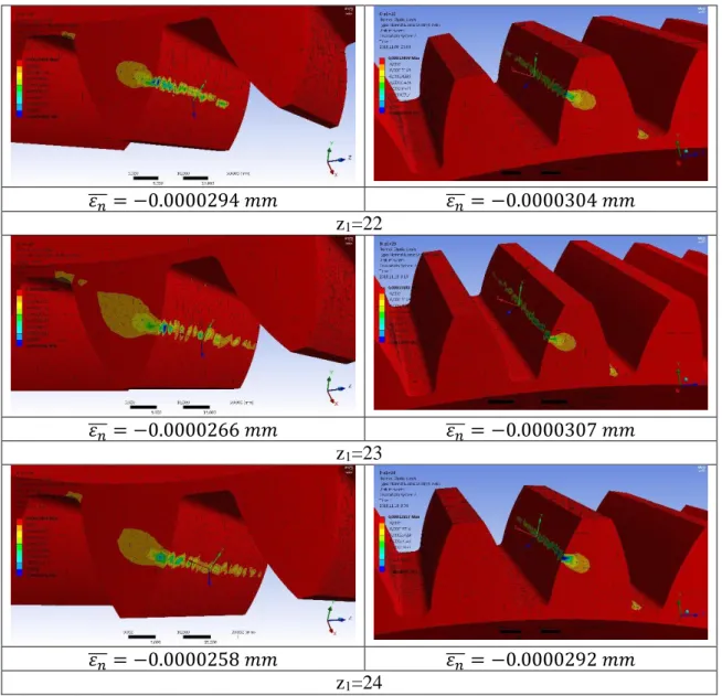
The normal elastic strain has been calculated for the tooth contact zone (Figure 8). It is defined on perpendicular direction for the tooth surface [8, 9, 13].
Driving gear Driven gear
𝜀𝑛
̅̅̅ = −0.0000334 𝑚𝑚 𝜀̅̅̅ = −0.000036 𝑚𝑚 𝑛 z1=20
𝜀𝑛
̅̅̅ = −0.0000274 𝑚𝑚 𝜀̅̅̅ = −0.0000333 𝑚𝑚 𝑛 z1=21
-6,104
-4,417
-4,906
-5,125 -5,043
-7,5 -7 -6,5 -6 -5,5 -5 -4,5 -4
19 20 21 22 23 24 25
Normal stress (MPa)
Number of teeth of the driving gear
Number of teeth of the driving gear - Normal stress (driven gear)
9 𝜀𝑛
̅̅̅ = −0.0000294 𝑚𝑚 𝜀̅̅̅ = −0.0000304 𝑚𝑚 𝑛 z1=22
𝜀𝑛
̅̅̅ = −0.0000266 𝑚𝑚 𝜀̅̅̅ = −0.0000307 𝑚𝑚 𝑛 z1=23
𝜀𝑛
̅̅̅ = −0.0000258 𝑚𝑚 𝜀̅̅̅ = −0.0000292 𝑚𝑚 𝑛 z1=24
Figure 8. Normal elastic strain results for every bevel gear pairs
a) driving bevel gear -0,0000334
-0,0000274
-0,0000294 -0,0000266
-0,0000258
-3,41E-05 -3,21E-05 -3,01E-05 -2,81E-05 -2,61E-05 -2,41E-05 -2,21E-05
19 20 21 22 23 24 25
Normal elastic strain (mm)
Number of teeth of the driving gear
Number of teeth of the driving gear - Normal elastic strain (driving gear)
10
b) driven bevel gear
Figure 9. The developed normal elastic strain in the function of the number of teeth
Based on the calculations the normal elastic strain could be seen in the function of the number of teeth of the driving bevel gear on Figure 9.
Based on the results the minimum normal elastic strain of the surface of the driving bevel gear is developed in case of z1=24 number of teeth in absolute value. The minimum normal elastic strain of the surface of the driven bevel gear is developed in case of z1=24 number of teeth in absolute value (Figure 9). That is why the increasing of the number of teeth of the driving gear the normal elastic strain will be increased in case of both connecting tooth surfaces.
3.4. Analysis of the normal deformation
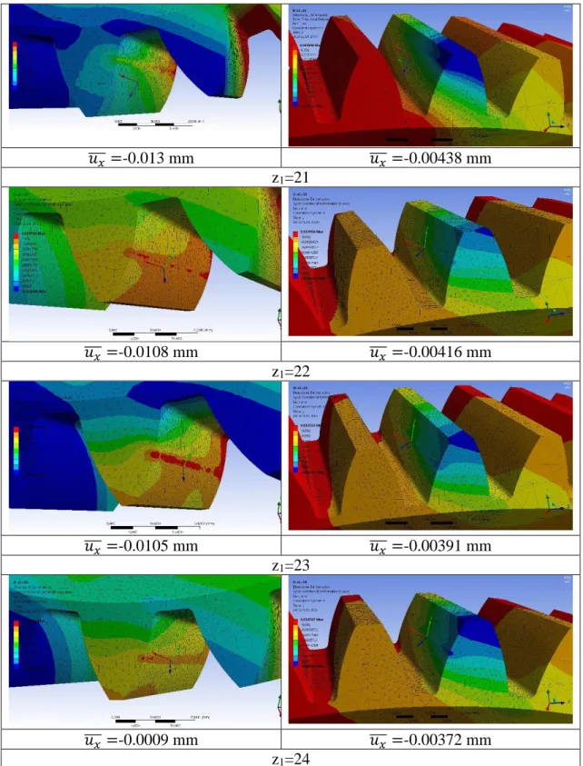
The normal deformation has been analyzed into the x direction which is perpendicular for the contact surfaces [8, 9, 13]. This direction is the most determinative because the main deformation is applied into the perpendicular direction of the contact surfaces (Figure 10).
Driving gear Driven gear
𝑢𝑥
̅̅̅ =-0.011 mm 𝑢̅̅̅ =-0.00476 mm 𝑥 z1=20
-0,000036
-0,0000333 -0,0000304
-0,0000307
-0,0000292
-0,000038 -0,000036 -0,000034 -0,000032 -0,00003 -0,000028 -0,000026
19 20 21 22 23 24 25
Normal Elastic strain (mm)
Number of teeth of the driving gear
Number of teeth of the driving gear - Normal elastic strain (driven gear)
11 𝑢𝑥
̅̅̅ =-0.013 mm 𝑢̅̅̅ =-0.00438 mm 𝑥 z1=21
𝑢𝑥
̅̅̅ =-0.0108 mm 𝑢̅̅̅ =-0.00416 mm 𝑥 z1=22
𝑢𝑥
̅̅̅ =-0.0105 mm 𝑢̅̅̅ =-0.00391 mm 𝑥 z1=23
𝑢𝑥
̅̅̅ =-0.0009 mm 𝑢̅̅̅ =-0.00372 mm 𝑥 z1=24
Figure 10. Normal deformation results for every bevel gear pairs
Based on the calculations the normal deformation could be seen in the function of the number of teeth of the driving bevel gear on Figure 10.
Based on the results the minimum normal deformation of the surface of the driving bevel gear is developed in case of z1=24 number of teeth in absolute value. The minimum normal deformation of the surface of the driven bevel gear is developed in case of z1=24 number of teeth in absolute value (Figure 11). That is why the increasing of the number
12
of teeth of the driving gear the normal deformation will be increased in case of both connecting tooth surfaces.
a) driving bevel gear
b) driven bevel gear
Figure 11. The developed normal elastic strain in the function of the number of teeth CONCLUSION
The aim of the research is the analysis of the modification of the number of teeth of the driving gear in the function of the TCA parameters (normal stress, normal, elastic strain and normal deformation).
Before the TCA the determination of the geometric parameters is needed. We have worked out a new-type computer aided software which is helped us for the facilitation of the calculation process. This software is determined the necessary geometric parameters
-0,011 -0,013
-0,0108
-0,0105
-0,0009
-0,014 -0,012 -0,01 -0,008 -0,006 -0,004 -0,002 0
19 20 21 22 23 24 25
Normal deformation (mm)
Number of teeth of the driving gear
Number of teeth of the driving gear - Normal deformation (driving gear)
-0,00476
-0,00438
-0,00416 -0,00391
-0,00372
-0,0049 -0,0046 -0,0043 -0,004 -0,0037 -0,0034 -0,0031
19 20 21 22 23 24 25
Normal deformation (mm)
Number of teeth of the driving gear
Number of teeth of the driving gear - Normal deformation (driven gear)
13
and the profile curves of the bevel gear pairs. After the process the CAD models of the designed gears have to be created. Knowing of the profile curves an interpolation B-spline is fitted into the calculated points.
Based on the CAD models of the analyzed gears the TCA analysis could be done. We have designed five types of bevel gear pairs. We have done the TCA analysis for every gear pairs.
The effect of the normal stress, normal elastic strain and the normal deformation has been analyzed between the contact surfaces. After the analysis we have evaluated the received results and created the functions separately for the driving gear and the driven gear. We could determine the consequences from this functions.
ACKNOWLEDGEMENT
This research was supported by the János Bolyai Research Scholarship of the Hungarian Academy of Sciences.
REFERENCES
[1] Argyris, J., Fuentes, A., Litvin, F. L.: Computerized integrated approach for design and stress analysis of spiral bevel gears, Computer methods in applied mechanics and engineering, Elsevier, 2002, pp. 1057 - 1095
[2] Dudás, I.: Gépgyártástechnológia III., A. Megmunkáló eljárások és szerszámaik, B.
Fogazott alkatrészek gyártása és szerszámaik, Műszaki Kiadó, Budapest, 2011.
[3] Dudás, L.: Kapcsolódó felületpárok gyártásgeometriai feladatainak megoldása az elérés modell alapján, Kandidátusi értekezés, Budapest, TMB, 1991., p.144., 2005.
06. 29.
[4] Dudley, D. W.: „Gear Handbook”, MC Graw Hill Book Co. New York-Toronto- London, 1962.
[5] Erney, Gy.: Fogaskerekek, Műszaki Könyvkiadó, Budapest, 1983., p. 460.
[6] Fuentes, A., Iserte J. L., Gonzalez – Perez, I., Sanchez – Marin, F. T.: Computerized design of advanced straight and skew bevel gears produced by precision forging, Computer methods in applied mechanics and engineering, Elsevier, 2011, pp. 2363 - 2377
[7] Goldfarb, V., Trubachev, E., Barmina, N.: Advanced Gear Engineering, Springer, 2018, p. 197., ISBN 978-3-319-60398-8
[8] Kozák, I., Szeidl, Gy.: Fejezetek a szilárdságtanból, Kézirat, 2008 – 2012, Miskolci Egyetem, p. 284. elektronikus jegyzet
[9] Litvin, F. L., Fuentes, A.: Gear Geometry and Applied Theory, Cambridge University Press, 2004., ISBN 978 0 521 81517 8
[10] Litvin, F. L.: A fogaskerékkapcsolás elmélete. Műszaki Könyvkiadó, Budapest, 1972.
[11] Rohonyi V.: Fogaskerékhajtások. Műszaki Könyvkiadó, Budapest, 1980.
[12] Terplán Z.: Gépelemek IV., Kézirat, Tankönyvkiadó, Budapest, 1975., p. 220.
[13] Páczelt, I., Szabó, T., Baksa, A.: A végeselem módszer alapjai, Miskolci Egyetem, p. 243.