77
2019, VOL. 3, NO:4, 77-83
www.dergipark.gov.tr/ijastech
Tooth contact analysis of x-zero helical gears by the modification of the tooth trace
Sándor Bodzás
0000-0001-8900-2800
Department of Mechanical Engineering, Faculty of Engineering, University of Debrecen, Debrecen, 4028, Hungary
---
1. Introduction
The helical gears are used very frequently in many me- chanical constructs [6, 8, 9, 10, 11, 12, 13]. The one of the main applications is on the gear transmissions of vehicles (Figure 1).
Fig. 1. A Volkswagen gear transmission [14]
Fig 2. The derivation of the involute surface [1, 6]
The teeth are picked up the loads at the same time and ceased at the same time. The connection is continuously. The force effects from the friction are worked into two directions on the same tooth. Based on this the helical gear is run more Abstract
The helical gear pairs are widely used in different mechanical constructs. The main advantage is the good efficiency and the low noise during the connection.
We have worked out a computer software with which the designing process of the helical gears could be eased. Based on the calculated gear parameters the CAD models of the elements could be prepared. Knowing of the geometries the assem- bly could be created based on the fixed freedom degrees and the elementary centre distance. We have designed five types of gear pairs. The differences are only the different tooth traces. All of other parameters have not been modified.
The aim of this research is the function between the tool trace and the mechan- ical parameters. Using of the TCA the mechanical parameters of the connecting elements on the contact zone could be analyses by different loads.
We have done this analysis which means we have analyzed the effect of the modified parameter for the normal stress, normal deformation and the normal elastic strain on the contact zone. Based on the results we have prepared diagrams for the analysis of the correlations between the changing parameters.
Before the real production the TCA is suggested because of the determination of the estimated mechanical parameters. If these parameters would not give re- quired results it could be possible to return to the geometric designing process and modify the geometric parameters.
Keywords: Helical gear, tooth trace, TCA, CAD, normal
* Corresponding author Sándor Bodzás
bodzassandor@eng.unideb.hu Address:Department of Mechanical Engineering, University of Debrecen, Debrecen, 4028, Hungary
Tel: +36706002846
Researh Article
Manuscript Received 13.02.2019 Revised 10.09.2019 Accepted 14.11.2019
Doi: 10.30939/ijastech..526392
a
a
y1S
x1S
z1S
y1R
x1R
z1R
78 silently [2, 3, 5, 6, 11].
The disadvantage is the axial force which could be com- pensated by Herringbone gear [6].
Based on Figure 2. a tangential plane is turned around the basic cylinder on the K1R rotation coordinate system. The basic cylinder is situated on the K1S standing coordination system. This is the derivation of the involute helical surface (Figure 2.). [1, 6] An arbitrary oblique line of this tangential plane is describe an involute helical surface. Every planar section of this is verdant involute. The tangential plane of the basic cylinder is the connection plane (Figure 3) [3, 5, 6].
Fig. 3. The basic cylinders of the involute helical surfaces [1, 6]
The generator of the tooth surface is closed βa angle with the axis of the basic cylinder. The (90°- βa) is the helix angle of the involute helical surface [3, 5, 6, 7].
2. Designing of the x-zero helical gear pairs
The basic property of the x-zero gear drives is the con- nection is done on the pitch circle diameter, that is why the pitch circle diameter and the rolling circle diameter are the same [3, 5, 6]:
𝑎𝑜=𝑑1+ 𝑑2 2 𝑑1= 𝑑𝑤1
𝑑2= 𝑑𝑤2
Knowing of the geometric parameters from the refer- ences we have worked out a computer software because of the facilitation of the designing process [1].
We have designed five types of helical gears based on
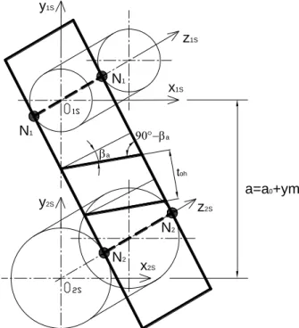
the modification of the tooth trace (Table 1). All of other parameters has been the same, only the tooth trace has been modified on the pitch cylinder (β0) (Figure 4):
𝛽𝑎= asin(𝑐𝑜𝑠𝛼0∙ 𝑠𝑖𝑛𝛽0)
Fig. 4. The position of the β0 angle The involute profile angle on the pitch circle:
𝛼𝑜ℎ= acos(𝑡𝑎𝑛𝛽𝑎/𝑡𝑎𝑛𝛽0)
a) The profiles of the pinion
b) The profiles of the driven gear
Fig. 5. The calculated gear profiles in the function of the tooth trace
Fig. 6. The CAD models of the designed gear pairs y2S
x2S
z2S
1S
z1S
x1S N1
N1
N2
N2
a
a
toh
a=a0+ym
a0
0 0
Od1 Od2
(1) (2) (3)
(5) (4)
79 Table 1. The parameters of the designed helical gear pairs
Gear drive I.
Gear drive II.
Gear drive III.
Gear drive IV.
Gear drive V.
Axial module (m) [mm] 10
Number of teeth of the pinion (z1) 20
Number of teeth of the driven
gear (z2) 30
Tooth trace (β0) [°] 15 17 19 21 23
Profile angle (α0) [°] 20
Axial pitch (t0h) [mm] 32.524 32.851 33.226 33.651 34.129
Addendum (ha) [mm] 10
Bottom clearance (c) [mm] 2.5
Dedendum (hf) [mm] 12.5
Whole depth (h) [mm] 22.5
Pitch circle diameter of the pinion (d
1) [mm] 207.055 209.138 211.524 214.229 217.272
Pitch circle diameter of the driven
gear (d2) [mm] 310.582 313.707 317.286 321.343 325.908
Elementary centre distance (a0)
[mm] 258.819 261.422 264.405 267.786 271.590
Tip circle diameter of the pinion
(da1) [mm] 227.055 229.138 231.524 234.229 237.272
Tip circle diameter of the driven
gear (da2) [mm] 330.582 333.707 337.286 341.343 345.908
Root circle diameter of the pinion (df
1) [mm] 182.055 184.138 186.524 189.229 192.272
Root circle diameter of the driven
gear (df2) [mm] 285.582 288.707 292.286 296.343 300.908
Backlash (js) [mm] 1.626 1.642 1.661 1.682 1.706
Working depth (hw) [mm] 20
Tooth thickness (Sax) [mm] 15.449 15.604 15.782 15.984 16.211
Basic circle diameter of the pinion (da
1) [mm] 193.756 195.460 197.403 199.596 202.050
Basic circle diameter of the driven ge
ar (da2) [mm] 290.634 293.190 296.105 299.394 303.076
Transmission ratio (i) 1.5
The calculated profiles of the pinion and the driven gear could be seen in the function of the modification of the tooth trace on Figure 5. The involute profile is changed in the func- tion of the modification of the tooth trace.
Knowing of the calculated parameters of the designed gear pairs the CAD (Computer Aided Designing) models of the elements could be prepared by Solidworks software (Fig- ure 6).
Our developed program can export the profile curves of the elements in txt format. Based on this points interpolated B-spline [4] could be fitted for the points by Solidworks soft- ware. After that the CAD models could be built up [1].
3. Tooth contact analysis (TCA)
The aim of the TCA is the analysis of the established mechanical parameters of the gear pairs before the produc- tion. If the analyzed mechanical parameters are not appro- priate there are possibilities for the modification of the ge-
ometric parameters of the gears for the better working con- ditions [5, 7, 8].
Fig.7. The adoption of the FEM mesh
Face sizing type meshing has been used on the contact zone around a sphere having 35 mm. The type of the plane figure has been a triangle. The applied density of the meshing has been 2 mm (Figure 7). The meshing has been handed out equally along the tooth length.
80 The applied material has been structural steel (Table 2).
Table 2. The parameters of the applied materials
Density 7850 kg/m3
Yield limit 250 MPa Ultimate strength 460 MPa 3.1 Defining of the load and boundary conditions
During the analysis, 3 coordinate systems have been de- fined: two standing coordinate systems on the middle rota- tion axes of the gear pairs (K1S, K2S), one coordinate system
on the contact zone of the gears.
All freedom degrees of the driven gear have been fixed.
Five freedom degrees of the pinion have been fixed, only the rotation around the axis of rotation has been permitted.
The pinion has been loaded by 500 Nm moment. The contact tooth surfaces of the gear pairs have been analyzed.
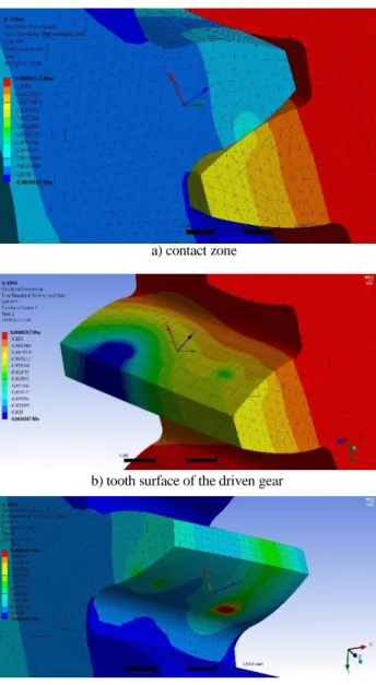
3.2 Analysis of the normal stresses on the tooth surfaces The normal stress is defined perpendicularly for the tooth surfaces on the coordinate system on the contact zone of the gears. These direction is the most determinative in aspect of tooth deformation.
a) contact zone b) tooth surface of the driven gear
c) tooth surface of the pinion
Fig. 8. Normal stress distribution (m=10 mm, z1=20, z2=30, β0=15°)
a) pinion b) driven gear Fig. 9. The normal stress results in the function of the tooth trace
81 3.3 Analysis of the normal elastic strain on the tooth surfaces
a) contact zone b) tooth surface of the driven gear
c) tooth surface of the pinion
Fig. 10. Normal elastic strain distribution (m=10 mm, z1=20, z2=30, β0=15°) The normal elastic strain is determined perpendicularly
for the tooth contact surface. This direction is the most de- terminable in the tooth connection.
a) pinion
b) driven gear
Fig. 11. The normal stress results in the function of the tooth trace
3.4 Analysis of the normal deformation on the tooth sur- faces
The deformation could be determinable to many direc- tions. In case of the tooth connection the main direction is the normal direction which is perpendicular for the contact sur- faces. It could be determined by the help of the coordinate system on the contact zone of the gears (Figure 12.a).
The normal stress results in the function of the tooth trace could be seen on Figure 9.
A little fluctuation could be seen on the pinion side (Fig- ure 9.a). The lowest normal stress in absolute value could be achieved in case of Gear drive I.
The normal stress is increased until β0=19° tooth trace.
After that the normal stress is started decreasing (Figure 9.b) on the driven gear side. The lowest normal stress in absolute value could be achieved in case of Gear drive I.
According to the normal stress distribution the Gear drive I has better stress results.
The normal elastic strain results in the function of the tooth trace could be seen on Figure 11.
The lowest result could be found in case of β0=15° in ab- solute value on the pinion (Figure 11.a). The highest result could be found in case of β0=23° in absolute value.
The lowest result could be found in case of β0=15° in ab- solute value on the driven gear (Figure 11.b). The highest re- sult could be found in case of β0=19° in absolute value.
According to the normal elastic strain distribution the Gear drive I has better results beside the constancy of the other gear parameters (Figure 11).
The normal deformation results in the function of the tooth trace could be seen on Figure 13.
82 The lowest result could be found in case of β0=21° in ab-
solute value on the pinion (Figure 13.a). The highest result could be appeared in case of β0=17° in absolute value. This value is outstanding high than the other deformation values.
The lowest result could be found in case of β0=15° in ab- solute value on the driven gear (Figure 13.b). The highest re- sult could be appeared in case of β0=19° in absolute value.
a) contact zone
b) tooth surface of the driven gear
c) tooth surface of the pinion
Fig. 12. Normal deformation distribution (m=10 mm, z1=20, z2=30, β0=15°)
a) pinion
b) driven gear
Fig. 13. The normal deformation results in the function of the tooth trace
4. Conclusions
The helical gear pairs are used in many mechanical con- structions for instance vehicle’s gear transmissions or work- ing machines. The TCA is important because of the achieve- ment of better mechanical conditions during the working.
The modification of the geometric parameters of the gear pairs is important due to the optimized TCA’s results.
Five types of x-zero helical gear pairs have been designed.
Only the tooth trace has been modified during the designing process. We have worked out a computer program with which the designing process could be easier. After the de- signing process the CAD models and the assembly construc- tion could be created for the TCA.
TCA has been done for the analysis of the normal stresses, normal deformations and normal elastic strains. Our purpose is the comparative analysis of the TCA’s results in the func- tion of the modification of the tooth trace on the tooth contact zone. After that the correlations between the modified gear parameters and the TCA results could be determinable.
Based on our results we could achieve better TCA’ re- sults if we apply lower tooth trace beside the constancy of other gear parameters.
83 Acknowledgment
„ SUPPORTED BY THE ÚNKP-18-4NEW NATIONAL EXCELLENCE PROGRAM OF THE MINISTRY OF HUMAN CAPACITIES”
This research was supported by the János Bolyai Re- search Scholarship of the Hungarian Academy of Sci- ences.
Nomenclature
β0 : the tooth trace on the pitch cylinder (°)
βa : the tooth trace on the basic cylinder (°)
KS(xS, yS, zS) : the stationary coordinate sys- tem of the helical gear
KR(xR, yR, zR) : the stationary coordinate sys- tem of the helical gear
φ1 : angular displacement (°) a : centre distance (mm)
a0 : elementary centre distance (mm) y : specific increase of centre distance m : axial module (mm)
α0 : profile angle (°) t0h : axial pitch (mm)
ha : addendum [mm]
hf : dedendum [mm]
h : whole depth [mm]
d1,2 : pitch circle diameters (mm) da1,2 : tip circle diameters (mm) df1,2 : root circle diameters (mm)
dw1,2 : rolling circle diameters (mm)
js : backlash (mm)
hw : working length (mm) Sax : tooth thickness (mm)
da1,2 : basic circle diameters (mm)
i : transmission ratio z1,2 : number of teeth References
[1] Bodzás, S. (2018). Ferde fogazatú fogaskerékpárok számítógéppel segített tervezése és modellezése, Műszaki Tudomány az Észak – Kelet Magyarországi Régióban 2018 Konferencia Előadásai, Debreceni Akadémiai Bizottság, Műszaki Szakbizottság, 25-41, ISBN 978-963-7064-37-1 [2] Dudás, I. (2011). Gépgyártástechnológia III., A. Megmunkáló
eljárások és szerszámaik, B. Fogazott alkatrészek gyártása és szerszámaik, Műszaki Kiadó, Budapest, 2011.
[3] Erney, Gy. (1983). Fogaskerekek, Műszaki Könyvkiadó, Bu- dapest, p. 460.
[4] Juhász, I. (1995). Számítógépi geometria és grafika, Miskolci Egyetemi Kiadó, Miskolc, p. 220
[5] Litvin, F. L., Fuentes, A. (2004). Gear Geometry and Applied Theory, Cambridge University Press, ISBN 978 0 521 81517 8
[6] Terplán, Z. (1975). Gépelemek IV., Kézirat, Tankönyvkiadó, Budapest, p. 220.
[7] Litvin, F. L., Fuentes, A., Gonzalez-Perez, I., Carnevali, L., Sep, T. M. (2002). New version of Novikov-Wildhaber, helical gears: computerized design, simulation of meshing and stress analysis, Computer Methods in Applied Mechanics and Engi- neering, Elsevier, 5707 – 5740
[8] Fuentes, A., Ruiz-Orzaez, R., Gonzalez Perez, I. (2014). Com- puterized design, simulation of meshing and finite element analysis of two types of geometry of curvilinear cylindrical gears, Computer Methods in Applied Mechanics and Engi- neering, Elsevier, 321 – 339.
[9] Jing, W., Aiqiang, Z., Gangqiang, W., Datong, Q., Teik, C. L., Yawen W., Tengjiao L. (2018). A study of nonlinear excitation modeling of helical gears with Modification: Theoretical analysis and experiments, Mechanism and Machine Theory, Elsevier, 314-335
[10] Mo, S., Ma, S., Jin, G., Gong J., Zhang, T., Zhu, S. (2018).
Design principle and modeling method of asymmetric involute internal helical gears, Journal of Mechanical Engineering Science, 1-12, DOI: 10.1177/0954406218756443 [11] Yanjun, P., Ning, Z., Pengyuan, Q., Mengqi, Z., Wang, L.,
Ruchuan, Z. (2018). An efficient model of load distribution for helical gears with modification and misalignment, Mechanism and Machine Theory, Elsevier, 151-168
[12] Radu George C., Sorin C. (2018). Contact analysis of helical gears by using finite element method, Proceedings of 2018 International Conference on Hydraulics and Pneumatics, Băile Govora, Romania, 172-176, ISSN 1454 – 8003 [13] Yifan H., Kangkang C., Hui M., Linyang C., Zhanwei L.,
Bangchun W. (2019). Deformation and meshing stiffness analysis of cracked helical gear pairs, Engineering Failure Analysis, 30-46
[14] https://www.kisspng.com/png-mechanical-gear-2649/
![Fig 2. The derivation of the involute surface [1, 6]](https://thumb-eu.123doks.com/thumbv2/9dokorg/1067204.70877/1.892.85.429.893.1059/fig-derivation-involute-surface.webp)