Fast DRR generation for 2D to 3D registration on GPUs
Gábor János Tornai and György Cserey
Faculty of Information Technology, Pázmány Péter Catholic University, Práter u. 50/a, H-1083, Budapest, Hungary
Ion Pappasa)
General Electric Healthcare, Akron u. 2, H-2040, Budaörs, Hungary
(Received 2 May 2012; revised 22 June 2012; accepted for publication 25 June 2012; published 19 July 2012)
Purpose: The generation of digitally reconstructed radiographs (DRRs) is the most time consuming step on the CPU in intensity based two-dimensional x-ray to three-dimensional (CT or 3D rotational x-ray) medical image registration, which has application in several image guided interventions. This work presents optimized DRR rendering on graphical processor units (GPUs) and compares perfor- mance achievable on four commercially available devices.
Methods: A ray-cast based DRR rendering was implemented for a 512×512×72 CT volume. The block size parameter was optimized for four different GPUs for a region of interest (ROI) of 400
×225 pixels with different sampling ratios (1.1%–9.1% and 100%). Performance was statistically evaluated and compared for the four GPUs. The method and the block size dependence were validated on the latest GPU for several parameter settings with a public gold standard dataset (512 × 512
×825 CT) for registration purposes.
Results: Depending on the GPU, the full ROI is rendered in 2.7–5.2 ms. If sampling ratio of 1.1%–9.1% is applied, execution time is in the range of 0.3–7.3 ms. On all GPUs, the mean of the execution time increased linearly with respect to the number of pixels if sampling was used.
Conclusions: The presented results outperform other results from the literature. This indicates that automatic 2D to 3D registration, which typically requires a couple of hundred DRR renderings to converge, can be performed quasi on-line, in less than a second or depending on the application and hardware in less than a couple of seconds. Accordingly, a whole new field of applications is opened for image guided interventions, where the registration is continuously performed to match the real-time x-ray.© 2012 American Association of Physicists in Medicine. [http://dx.doi.org/10.1118/1.4736827]
Key words: DRR, GPU, 2D to 3D registration
I. INTRODUCTION
Digitally reconstructed radiographs (DRRs) are simulated x-ray images generated by projecting 3D computed tomogra- phy (CT) images or 3D reconstructed rotational x-ray images.
In particular, DRRs are used in patient position monitoring during radiotherapy or image guided surgery for automatic 2D to 3D image alignment (registration) and overlay. The DRR rendering is usually the most time-consuming step and performance bottleneck in these applications. In this paper, we present a solution to accelerate the 2D to 3D registration performance by implementing and optimizing the DRR exe- cution on state of the art graphical processing units (GPUs).
GPUs have become efficient accelerators of several comput- ing tasks. They are kilo-core devices with high computing ca- pacity and bandwidth.
There are numerous papers1presenting a wide spectrum of results connected to acceleration of DRR generation or reduc- ing the required number of renderings.2These results can be divided into two classes: results relying only on algorithmic improvements implemented on CPU and ones based on GPU computing. TableIpresents a condensed summary of the re-
ported results in acceleration of DRR rendering. In addition, it presents specific results in 2D to 3D registration that are straightforward in the way of DRR rendering, as well. The accurate ROI selection based on a planned target volume to- gether with the DRR rendering performed on the GPU in a recent work3 indicates the viability of quasi real time oper- ability. Therefore, the evaluation presented in this work is nec- essary, to show how fast the DRR rendering can be done on the GPU. All the other results of 2D to 3D registration are performed in 20–1000 s. Furthermore, the rendering time of a single DRR is in the range of 25–70 ms.
II. METHODS II.A. GPU overview
Recent GPU models are capable of nongraphics opera- tions and are programmable through general purpose appli- cation programming interfaces (APIs) like C for CUDA10or OpenCL.11In this paper, C for CUDA nomenclature is used.
The description below is brief overview of GPUs, and only
TABLEI. Summary of published results connected to fast DRR rendering and 2D to 3D registration.
Perf. DRR Perf. Reg.
Hardware Year ROI size (ms) (s) Comments Group
Intel Xeon (2.2 GHz) 2005 256×256 50 ms 100 s SW cache, 0.4-6 h preproc Russakoffet al.(Ref.4) Intel Pentium 4 (2.4 GHz) 2005 200×200 – 160–1100 s SW cache, no preproc Rohlfinget al.(Ref.5)
Intel Xeon 2009 256×256 – 30–120 s ROI randomly sampled (5%) Birkfellneret al.(Ref.6)
Intel Core (1.8 GHz octal) 2009 256×172 50 ms – Multithreaded ray cast Dorgham (Ref.7)
GeForce 7600 GS (12 cores) 2007 512×512 54–74 ms – Voxel based, (6×10⁶voxel) Spoerket al.(Ref.8) GeForce 7800 GS (16 cores) 2008 256×256 73 ms – X-ray postprocessing imitation Kubiaset al.(Ref.9) GeForce 8800 GTS (96 cores) 2012 Task dependent – 0.39–0.74 s Special ROI selection Gendrinet al.(Ref.3)
those notations are summarized that have an impact on the performance of the DRR rendering.
A function that can be executed on the GPU is called a ker- nel. Any call to a kernel must specify an execution configura- tion for that call. This defines not just the number of threads to be launched but the arrangement of groups of threads to blocks and blocks to a grid. The dimensionality of a block can be one, two, or three while the grid is either one- or two- dimensional. The number of threads in a block is referred to as block size. For a given number of threads the block size has a great impact on performance and there are no explicit rules to find its optimal value so far. Threads of a block are orga- nized into warps. Threads in a warp are scheduled physically together on the device. The warp size is 32 on all GPUs that are employed in this work. As a consequence, the vendor ad- vises block sizes that are multiples of 32. The parallel thread execution (PTX) (Ref.12) is an intermediate, device indepen- dent GPU language above assembly. During the compilation, the kernel is translated first to PTX and then compiled to de- vice dependent code.
II.B. Algorithm and implementation rules
A ray is a line segment determined by the virtual x-ray source position and a pixel location on the virtual image plane in the 3D scene (Fig.1). The logarithm of a pixel intensity is the line integral of the ray segment inside the volume. The al- gorithm starts with the calculation of the direction vector of the ray. Then the normalization follows that resizes the direc- tion vector to be equal to a side of a voxel in the 3D volume.
FIG. 1. DRR rendering geometry. Rays are determined by virtual x-ray source and sampling locations on the virtual image plane, inside the ROI.
Pixel intensities are approximated line integrals along the dashed line seg- ments (volume interior). ROI is resampled for each DRR rendering. Simi- larly, the CT position and orientation are varied by uniform distribution.
Once the entry and exit points of the ray are calculated on the volume bounding box, the main loop that approximates the line integral is executed (Listing 1).
The following rules were applied to optimize the code:
(Rule1) Place the volume in a 3D texture memory. It is a spe- cial memory object hidden from direct accesses, cached and capable of different interpolations. (Rule2) Instead of nearest neighbour choose linear interpolation. (Rule3) Slow “if else”
branches shall be replaced with ternary expressions that are compiled to selection PTX instructions that are faster than any kind of branching PTX instructions. (Rule4) Avoid division if possible and use the less precise, faster type. (Rule5) If the de- nominator is used multiple times calculate inverse value and multiply with it.
Listing 1. Main loop inside the kernel: line integral approx- imation along a ray. “integ” is the integral on the voxel inten- sities traversed, “pos” is the actual position inside the volume, its initial value is on the volume surface, “dir” is a voxel sized direction vector. “Image3D” is the 3D texture with linear in- terpolation and “tex3D” is a built in texture reading function.
“C” and “K” are optional scaling constants.
floatinteg=0.0f;
for(int j=0; j<int(ray_length);++j) {
integ+=tex3D(Image3D, pos.x, pos.y, pos.z);
pos.x+=dir.x;
pos.y+=dir.y;
pos.z+=dir.z;
}
PixelValue[threadID]=exp(-C*integ+K);
II.C. Data and measurement
The rendering plane is choosen to be 300 × 300 mm2 with a resolution of 750×750. An ROI size of 16×9 mm2 (400×225 pixels) is selected within it. The ROI is sampled randomly: the locations of the pixels are choosen by a 2D uniform distribution. Seven sampling ratios (1.1%–9.1%) and full sampling are investigated: rendering of 1024, 1536, 2048, 3072, 4096, 6144, 8192, and 90 000 pixels (full sampling, 400× 225 pixels). This last case is referred to as full ROI DRR. Each pixel intensity is calculated by one thread on the GPU. So the number of pixels are equal to the number of threads launched on the device. The block size parameter
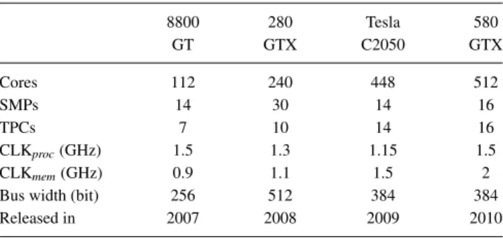
TABLEII. GPUs used in this work. Streaming multiprocessors (SMPs) are a compact group of cores. Texture processing clusters (TPCs) are responsible for texture memory that is a cached read only memory employed in this work.
8800 280 Tesla 580
GT GTX C2050 GTX
Cores 112 240 448 512
SMPs 14 30 14 16
TPCs 7 10 14 16
CLKproc(GHz) 1.5 1.3 1.15 1.5
CLKmem(GHz) 0.9 1.1 1.5 2
Bus width (bit) 256 512 384 384
Released in 2007 2008 2009 2010
was optimized for each number of pixels and GPU pair. This amounts to 32 cases (4 GPUs, 8 thread values). For each block size value, more than 1000 kernel executions were measured. In this work the dimensionality of the block size parameter is one so is the grid size.
The pixel locations were resampled for each kernel execu- tion. Similarly, for each kernel execution the initial reference pose of the CT volume was varied (perturbed) in the range of
±20 mm and ±15◦by uniform distribution. The perturbation of the volume pose and the resampling of the pixel locations mimics the repetitive DRR rendering need of a 2D to 3D reg- istration process. It shall be noted, other results6,13,14showed that 2D to 3D image registration algorithms can robustly con- verge with good accuracy even if only a few percent of the pixels are sampled randomly.
For the execution time measurements a CT scan (manu- factured by GE Healthcare, CT model Light Speed 16) of a radiological torso phantom (manufactured by Radiology Sup- port Devices, Newport Beach, CA, model RS-330) was used.
The resolution of the reconstructed image was 512× 512
×72 with data spacing (0.521 mm, 0.521 mm, 1.25 mm). For validation purposes from the gold standard data set15 a 512
×512 ×825 CT with data spacing (0.566 mm, 0.566 mm, 0.4 mm) was used. Measurements were done on four Nvidia (Santa Clara, CA) GPUs which were state of the art devices (TableII). GPU driver and CUDA toolkit (compilation tools and libraries) were developed by Nvidia, their version were
260.16.21 and 3.2, respectively. The hosting PC contained an Intel Core2 Quad CPU (2.66 GHz) and 4 GB of system mem- ory, running Linux kernel 2.6.32-5-amd64.
III. RESULTS
Table III presents mean and standard deviation of opti- mized execution times together with the optimal block size value. For comparison, the mean of execution times with naive block size value (256) are also presented. As an ex- ample, Fig.2shows the block size dependences of rendering 1024, 1536, and 2048 pixels on a 580 GTX GPU.
Computation time dependence on block size is in the range of 10%–60% on 8800 GT and 280 GTX GPUs in the case of sampled DRRs if optimal execution time is considered as 100%. This variation is in the range of 23%–145% on Tesla C2050 and 580 GTX GPUs. If full ROI DRRs are considered, the variation is in the range of 10%–34% on all devices. The mean of texture cache hit ratio is 15% in the case of sampled DRRs on all devices. However, in the case of full ROI DRRs the hit rate is nearly perfect, so the proportional time to com- pute a pixel intensity is reduced by 90% in average.
Rendering times of full ROI DRRs are comparable with other results from the literature (TableI). In this work ap- proximately 6.3×10⁶ voxels are visited in order to render a full ROI DRR. This is a 7-fold speedup compared to the result of Spoerket al.8(TableI) with similar number of vox- els rendered and normalized by the ROI. Unfortunately, there are no explicit results on sampled DRR rendering. The avail- able ones are implicit and based on 2D to 3D registration performance.6
IV. DISCUSSIONS
In this paper, optimization and measurements of a fast DRR rendering were presented, based on an algorithm imple- mented in C for CUDA executed on four contemporary GPUs.
In our implementation the 3D texture memory is used to gain advantage of the caching mechanism and the linear interpola- tion. Furthermore, the block size parameter was optimized for 32 different cases (4 GPUs, 8 thread values). These optimized values differ from values suggested by the vendor in many
TABLEIII. Optimized execution characteristics. Columns “to” represent the means and standard deviations of optimized execution times of DRR computing kernel. Columns “bs” show optimized block sizes for device and thread number pairs. Columns “tn” present mean of execution times with naive block size of 256.
8800 GT 280 GTX Tesla C2050 580 GTX
No.of pixels to(μs) bs tn(μs) to(μs) bs tn(μs) to(μs) bs tn(μs) to(μs) bs tn(μs)
1024 1257±122 160 1404 547±66 96 882 417±39 10 1020 297±22 8 727
1536 1588±137 10 1978 826±110 160 1080 510±21 14 1006 342±18 16 709
2048 2128±183 14 2923 1144±150 12 1258 690±11 32 1000 391±17 16 697
3072 3016±223 8 4056 1480±112 8 1934 886±46 32 1705 550±21 192 677
4096 3922±338 10 6126 1922±149 10 2536 1159±81 64 1818 700±37 128 702
6144 5815±488 16 9270 2641±188 10 3992 1508±96 64 2478 1006±56 192 1307
8192 7300±637 32 7972 3424±222 10 4667 2222±242 128 2907 1290±80 256 –
full ROI 5269±575 128 7060 4545±425 32 5963 3989±628 128 4382 2666±600 128 3131
FIG. 2. Block size dependence of average execution time of rendering 1024, 1536, and 2048 pixels from the 400×225 ROI on 580 GTX GPU from the 72 slice and the gold standard 825 slice CT, respectively. The block size dependence is nearly identical in the two cases.
cases. The execution time depending on the block size varies in the range of 20%–100%. It is a major optimization factor and there are no reported results concerning this fact from the field of DRR rendering or registration.
The ray cast algorithm is embarassingly parallel: the pixels are independent from each other and similarly, integrals of all disjoint segments of a ray are independent too. Another advantage of the algorithm is its independence from the pixel and virtual x-ray source locations. The performance bottleneck of the algorithm is its bandwidth limited nature.
For each voxel read instruction there are only four floating point additions.
However, the rendering time of a sampled DRR is remark- ably shorter than full ROI DRRs, the texture cache hit is only 15% in average in the former case thanks to the random di- rections of the rays, which cannot be captured efficiently by a cache optimized for locality.
The mean execution time is heavily block size dependent on all devices. The optimal block size values on the two older GPUs are unexpected and small (mostly 8–16). Their values are even smaller than a warp. However, the vendor suggests block sizes to be a multiple of 32 and at least 128. The two newer GPUs show a different characteristics. On Tesla GPU the optimal block sizes keep the number of active blocks on an SMP between 4–7. The best executions are achieved on 580 GTX when the number of launched blocks is multiple of the number of its SMPs. The optimal number of launched blocks per SMP varies from 1 to 8. Measurements suggest that two launched blocks per SM is optimal in a few cases (thread numbers: 4096, 6144, 8192) and near to the optimum in the other cases (2–15μsslower).
The results have been validated against a publicly avail- able gold standard data set for registration purposes15 on a 580 GTX GPU. The characteristics of the method were nearly identical on the two data set not counting the execution time scaling. This is shown on Fig.2for the following thread num- bers: 1024, 1536, and 2048. This validation indicates that our optimized method will behave similarly on bigger data set with different spacing values.
There are posibilities to improve even further the execution time. Line integral of disjoint segments can be computed in- dependently. This enables the complete integral of one pixel to be calculated by one or more blocks. A block works on a segment that can be either the complete line inside the volume or a fraction of it. In the case of full ROI DRRs the block and grid size can be chosen to be 2D, so a block renders a small rectangle of the ROI. This arrangement may be more effec- tive, since the locality is better than in the 1D case, which was used in this work. Completely different approaches can- not be much faster in the random case because rendering is bandwidth limited.
V. CONCLUSIONS
To automatically register the content of an x-ray projection to a 3D CT, 20–50 iteration steps are required. For each itera- tion, 10–20 DRRs are computed depending on the registration procedure. On the whole this amounts to 200–700 DRRs to be rendered for a registration to converge. DRR rendering is the most time consuming part of the 2D to 3D registration. Fol- lowing our implementation rules, the time requirements of a registration process can be decreased to 0.6–1 s if full-ROI DRRs are applied. If random sampling is used the time re- quirement of registration can be further reduced to 0.1–0.7 s resulting in quasi real-time operability.
ACKNOWLEDGMENTS
The Öveges Scholarship of GE, the professor partnership program of NVIDIA corporation, the Bolyai Janos Research
Scholarship of the Hungarian Academy of Sciences, and the support of Grants Nos. TÁMOP-4.2.1.B-11/2/KMR-2011- 0002 and TÁMOP-4.2.2/B-10/1-2010-0014 are gratefully acknowledged. The authors would like to thank Mátyás Letonay providing a glsl version of a naive DRR sampling algorithm and András Lassó encouraging the early steps of this work. Special thanks goes to Martin Tornai.
a)Electronic mail: ion.pappas@ge.com
1P. Markelj, D. Tomazevic, B. Likar, and F. Pernus, “A review of 3D/2D registration methods for image-guided interventions,”Med. Image Anal.
16, 642–661 (2012).
2B. P. Selby, G. Sakas, S. Walter, W. D. Groch, and U. Stilla, “Selective x-Ray reconstruction and registration for pose estimation in 6 degrees of freedom,” Int. Arch. Photogramm. Remote Sens. Spat. Inf. Sci.37, 799–
804 (2008).
3C. Gendrin, H. Furtado, C. Weber, C. Bloch, M. Figl, S. A. Pawiro, H. Bergmann, M. Stock, G. Fichtinger, and D. Georg, “Monitoring tumor motion by real time 2D/3D registration during radiotherapy,”Radiother.
Oncol.102, 274–280 (2012).
4D. Russakoff, T. Rohlfing, K. Mori, D. Rueckert, A. Ho, J. Adler, and C. Maurer, “Fast generation of digitally reconstructed radiographs using attenuation fields with application to 2D–3D image registration,” IEEE Trans. Med. Imaging24, 1441–1454 (2005).
5T. Rohlfing, D. B. Russakoff, J. Denzler, K. Mori, and C. R. Maurer, “Pro- gressive attenuation fields: Fast 2D–3D image registration without precom- putation,”Med. Phys.32, 2870–2880 (2005).
6W. Birkfellner, M. Stock, M. Figl, C. Gendrin, J. Hummel, S. Dong, J. Ket- tenbach, D. Georg, and H. Bergmann, “Stochastic rank correlation: A ro- bust merit function for 2D/3D registration of image data obtained at differ- ent energies,”Med. Phys.36, 3420 (2009).
7O. Dorgham, M. Fischer, and S. Laycock, “Accelerated generation of dig- itally reconstructed radiographs using parallel processing,” inProceedings of Medical Image Understanding and Analysis(Kingston University, UK, 2009), pp. 238–243.
8J. Spoerk, H. Bergmann, F. Wanschitz, S. Dong, and W. Birkfellner, “Fast DRR splat rendering using common consumer graphics hardware,”Med.
Phys.34, 4302–4308 (2007).
9A. Kubias, F. Deinzer, T. Feldmann, D. Paulus, B. Schreiber, and T. Brun- ner, “2D/3D image registration on the GPU,”Pattern Recog. Image Anal.
18, 381–389 (2008).
10NVIDIA, “CUDA c programming guide” (2011) .
11“OpenCL,” seehttp://www.khronos.org/opencl/(2011).
12NVIDIA, “Parallel Thread Execution ISA Version 3.0” (2012).
13L. Zollei, E. Grimson, A. Norbash, and W. Wells, “2D–3D rigid registra- tion of x-ray fluoroscopy and CT images using mutual information and sparsely sampled histogram estimators,” inProceedings of the 2001 IEEE Computer Society Conference on Computer Vision and Pattern Recogni- tion 2001(IEEE Computer Society, Kauai, HI, 2001), Vol. 2, pp. II–696–
II–703.
14L. Zollei, J. Fisher, and W. Wells, “A unified statistical and informa- tion theoretic framework for multi-modal image registration,” inInforma- tion Processing in Medical Imaging, Lecture Notes in Computer Science, Vol. 2732, edited by J. Noble, and C. Taylor (Springer, Berlin/Heidelberg, 2003), pp. 366–377.
15S. A. Pawiro, P. Markelj, F. Pernus, C. Gendrin, M. Figl, C. Weber, F. Kainberger, I. Nobauer-Huhmann, H. Bergmeister, M. Stock, D. Georg, H. Bergmann, and W. Birkfellner, “Validation for 2D/3D registration I: A new gold standard data set,”Med. Phys.38, 1481 (2011).