CHAPTER 5
Mechanically Aided Heat Transfer
Vincent W. Uhl Department of Chemical Engineering,
University of Virginia, Charlottesville, Virginia
I. Introduction 279 II. Heat Transfer in Agitated Vessels 280
A. Nonproximity Agitators 280 B. Proximity Agitators 297 III. Heat Transfer Resistance of Heating and Cooling Media 311
A. Heat Transfer in Jackets 311 B. Heat Transfer in Coils 314 IV. Design Considerations 315
A. Scale-up : 315 B. Heat Transfer on Vessel Side 317 C. Jacket and Coil Heat Transfer Rates and Construction 321
V. State of Knowledge and Problems to Be Solved 323
A. Nonproximity Agitators 323 B. Proximity Agitators 324 List of Symbols 325 References 327
I. Introduction
It is established practice to aid heat transfer to process materials with applied motion b o t h within the bulk of the material and proximate to the heat transfer surfaces. T h e applied motion enhances the rate of heat transfer beyond that provided by natural convection in the case of mobile fluids and that provided by conduction in the case of granular solids a n d very viscous materials. F o r most process situations this motion is promoted by either pumping or displacement by agitators of the material past fixed surfaces. F o r the case where the motive agency, such as a p u m p , is exterior to the heat exchanger, the heat transfer area can be predicted for surface geometries found in practice by the use of well-established relations to be found in works such as M c A d a m s (M5) a n d K e r n (K2). This chapter is concerned exclusively with heat transfer where agitation is provided by mechanical devices, viz., agitators, within the unit. Progress in this area has been considerable, especially
279
280 Vincent W. Uhl
for heat transfer to mobile fluids, despite the many variables required to describe the geometry of a typical agitated system.
II. Heat Transfer in Agitated Vessels
T o facilitate the organization of this subject, the types of agitators are categorized as proximity1 when the blades sweep close to or scrape the vessel wall and as nonproximity when the outer edge of the agitator blades rotate some distance from the wall. By far the greater proportion of the published investigations a n d the industrial applications are for the nonproximity types, viz., propellers, turbines, and paddles, which are ordinarily used for mobile to medium-viscous (0.1 to 1000 cp.) fluids. These smaller, generally higher speed agitators also facilitate heat transfer to the surfaces of coils immersed in the vessel as well as in jacketed vessel walls. The proximity type can either be close clearance as in the anchor or a wall scraping design; and these are used for very viscous, non-Newtonian, semisolid or granular solid materials.
A . NONPROXIMITY AGITATORS
The nonproximity agitators which are selected for heat transfer are the propeller, the various turbines, and the paddles, all of which provide a high circulation rate and allow a minimum of energy to be dissipated initially by shear forces in the vicinity of the impeller. Heat is transferred to either the vessel wall which is jacketed or t o the walls of an immersed tube coil. The term
"jacketed" will be considered to include a variety of constructions such as coils or half-coils welded to the vessel wall and coils cast in the wall. These will be discussed in Section IV,C a n d are illustrated in Fig. 16.
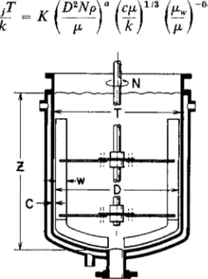
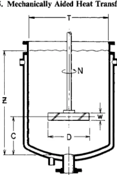
1. Heat Transfer to Jacketed Vessel Walls
Typical equipment is presented in Fig. 1, which also serves to present the symbols for the geometric parameters. A summary of conditions used in tests where paddles, turbines, and propellers were used t o p r o m o t e heat transfer is presented in Table I. Correlation constants from the results of these tests are given in Table II. These tables should be carefully studied; particular atten- tion should be accorded information such as vessel sizes, range of fluid viscosity, and the range of Reynolds numbers, so that the scope of work to date can be fully comprehended.
Dimensional analysis has provided a basis for successful correlations. F o r purposes of this development, the general case will be first presented and then the simplifications will be introduced which are needed to reduce the relation t o the form of the available correlations. As might be expected, the general
1 Although the word "proximity" is a noun, it and "nonproximity" are used here as adjectives, e.g., in "proximity fuse."
5. Mechanically Aided Heat Transfer
h τ i
281
il
Ν ΖC
FIG. 1. Jacketed vessel with pitched-blade turbine.
case is expressed by an equation similar to that used for forced convection heat transfer to conduits. However, in addition to the Nusselt, Reynolds, Prandtl, and "viscosity r a t i o " numbers, the general equation will contain a great number of ratios of linear dimensions to describe the effect of the com- plex geometry on the fluid m o t i o n . Such an equation, ascribed to Pursell (P6), for a given type of impeller and t a n k geometry is
However, it can be seen from a careful perusal of Table II, that almost all the studies listed were successfully correlated by a relation of the form
N o t e that despite differences in impeller and t a n k geometry for Eq. (2), the values of Κ fell within the relatively n a r r o w range of 0.36 to 0.74. This fact demonstrates that for the nonproximity impellers, the critical dimensions are the impeller diameter, D, and the tank diameter, T.
N o w a development will be undertaken which will yield the desired relation.
The reader should be prepared to expect a design relation of the form shown in Eq. (2) but with different exponents. In earlier correlations, adherence to precedent was more of a factor in determining the exponents a9 b9 and c (see Table II) t h a n the best representation of the data. Although the data indicated an absolute value of c larger t h a n 0.14, Chilton et al. (C2) admittedly applied 0.14 in deference to the well-known use of this value for forced convection in conduits in the classic work of Sieder and Tate (SI). Then hjT _
ÏÎD
2Np\
ÎCJA ίμΛ /T\ Îw\ ίΖ\ /C\/Β\
ίηΛ / « A LJ Nk [\ μ /, \ k )9\ μ )9 \DJ9 \D)9 \D), \DJ, \D), \ X )9 \y)r }
(2)
282 Vincent W. Uhl
Impeller Vessel
Investigators Description Diam.,
Z)(in.) w/D C\D
Speed,
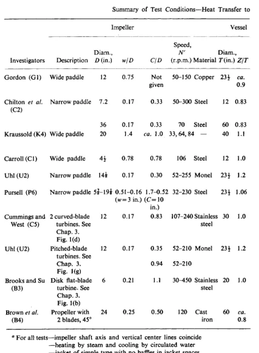
N' Diam., (r.p.m.) Material Γ (in.) Ζ/Γ Gordon (Gl) Wide paddle 12 0.75 Not 50-150 Copper 23i ca.
given 0.9
Chilton et al. Narrow paddle 7.2 0.17 0.33 50-300 Steel 12 0.83 (C2)
36 0.17 0.33 70 Steel 60 0.83 Kraussold (K4) Wide paddle 20 1.4 ca. 1.0 33,64,84 — 40 1.1
Carroll (CI) Wide paddle 41 0.78 0.78 106 Steel 12 1.0 Uhl (U2) Narrow paddle 14έ 0.17 0.30 52-255 Monel 23i 1.2 Pursell (P6) Narrow paddle 5 i - 1 9 i 0.51-0.16 1.7-0.52 32-230 Steel 23i 1.06
(w = 3in.) (C=10 in.)
Cummings and 2 curved-blade 12 0.17 0.83 107-240 Stainless 30 1.0
West (C5) turbines. See steel
Chap. 3.
Fig. 1(d)
Uhl (U2) Pitched-blade 12 0.17 0.35 52-210 Monel 23i 1.2 turbines. See
Chap. 3. 0.94 52-210
Fig. 1(g)
Brooks and Su Disk flat-blade 6 0.21 1.1 30-450 Stainless 20 1.0
(B3) turbine. See steel
Chap. 3.
Fig. 1(b)
Brown et al. Propeller with 24 0.25 0.50 120 Cast 60 ca.
(B4) 2 blades, 45° iron 0.8
a For all tests—impeller shaft axis and vertical center lines coincide
—heating by steam and cooling by circulated water
—jacket of simple type with no baffles in jacket spaces.
See Fig. 1. for representation of symbols.
Table I Summary of Test Conditions—Heat Transfer to
5. Mechanically Aided Heat Transfer
Jacketed Walls with Nonproximity Agitatorsa
283
Type bottom
Heating
and/or Type of cooling tests
Test liquids (no. of test runs with each liquid where reported given in parentheses)
Appurtenances in vessel Dished
Dished
Dished Dished
Flat Dished Dished
Dished
Dished
Dished
H Batch6 SAE10 oil (9); water (9)c SAE30 oil (8); kerosene ( l )c; SAE50 oil (8)
H + C Steady state Water (21); A-12 oil (12); 92%
glycerol (6); LM oil (11);
Batch* water (21); A-12 oil (11) H Batch6 Water (1) ; w-phenylene diamine (1) H Steady state Water and 3 oils with μ = 50, 220,
4000 cp. at20°C.
Batch6 Oil with μ = 220 cp. at 20°C.
Steady state Water (10)c; 4 aqueous glycerol solutions (20)
Cylinder oil (20); bodied linseed oil (19)
Water; 96% glycerol;
72% glycerol Η
H + C Batch6 H + C Batch6
None
Coil None and coil
None Coil None
Coil None and
baffles None
Η Steady state Water (4); toluene (1); ethylene glycol (1) ; mineral oil (4) ; glycerol (4)
Η Batch6 Bodied linseed oil (6) H + C Bodied linseed oil (19)
H + C Batch6 Water; SAE30 oil; SAE50 oil;
43 Bé corn syrup
Coil
None None None and
1,2, and 4 baffles Hemispherical C Steady state Nitration liquor (32) Blowpipe
6 Unsteady state.
c Reported results for high Reynolds numbers from these tests appear to be somewhat in error; see text.
Table II
Summary of Test Results—Heat Transfer to Jacketed Walls with Nonproximity Agitators Constants for heat transfer
equation0 Range
Investigators Impeller of Comments
type Κ a b c
Gordon (Gl)* Paddle 0.17 0.66 1/2 — 600-6 x l O5
Gordon ( G l )c Paddle 0.40 2/3 1/3 - 0 . 1 4 600-6 x l O5 Chilton et al. (C2) Paddle 0.36 2/3 1/3 - 0 . 1 4 300-3 χ 1 05 Kraussold (K4) Paddle 0.36 2/3 1/3 - 0 . 1 4 1 03- 6 x l 05 Carroll (CI) Paddle 0.60 2/3 1/3 — 0.14 1 . 5 x l 04- 7 x l 04
Uhl (U2) Paddle 0.415 2/3 1/3 — 0.24 20-4000 Baffled and unbaffled
Pursell (P6)d Paddle 0.112 3/4 0.44 — 0.25 600-5 χ 1 05 Cummings and West (C5)/Two curved-blade turbines6 0.60 2/3 1/3 - 0 . 1 4 2 x l 03- 8 x l 05
Uhl (U2) Pitched-blade turbine6 0.44 2/3 1/3 - 0 . 2 4 80-200 Low position, C = 4£ in.
0.53 2/3 1/3 - 0 . 2 4 20-120 Intermediate position, C = 11 in.
Brooks and Su (B3) Disk flat-blade turbine6 0.54 2/3 1/3 — 0.14 40-3 χ 105 Unbaffled 0.74 2/3 1/3 - 0 . 1 4 300-3 χ 105 1, 2, or 4 baffles Brown et al. (B4) Propeller 0.54 2/3 1/4 - 0 . 1 4 2 x 10³ 1 point
b Per Gordon (Gl), and for oil data only.
0 Per Cummings and West correlation (C5), and for oil data only.
d For complete equation correlating PurselFs data (P6), see Eq. (4) in text.
e For description of turbines, see Chapter 3, Fig. 1.
f Interpretation of Κ = 0.60 is by author.
284 Vincent W. Uhl
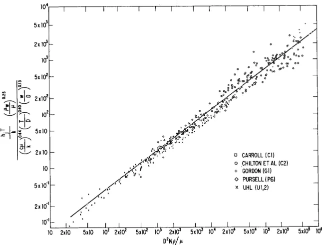
5. Mechanically Aided Heat Transfer 285 Kraussold (K4), Cummings and West (C5), Carroll ( C I ) , a n d Brown et al (B4) did likewise, all m o r e or less influenced by Chilton et al Uhl ( U I , U2) found that c should be —0.24 for nonproximity impellers and this has been confirmed by the considerable work of Pursell. The precedent of 2/3 for a a n d 1/3 for b was certainly due to Chilton etal. Pursell recorrelated all paddle d a t a readily available, namely, Carroll ( C I ) , Chilton et al (C2), G o r d o n ( G l ) , Uhl ( U I ) , along with fresh data of his own t o produce this general relation which is considered t o represent more closely the test d a t a from available sources.
k
F u r t h e r support for an exponent, a, greater t h a n 2/3 was given by Kraussold whose work indicated a to be 0.72.
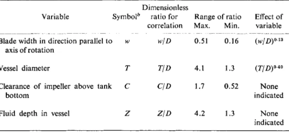
Pursell's work further included the effect of four of the dimensional variables in Eq. (1) which have been tabulated with his results in Table III.
Table III
Effect of Dimensional Variables on Rate of Heat Transfer in Jacketed Agitated Vessels*
Dimensionless
Variable Symbol6 ratio for Range of ratio Effect of correlation Max. Min. variable Blade width in direction parallel to w w/D 0.51 0.16 (w/D)013
axis of rotation
Vessel diameter Τ T/D 4.1 1.3 (Γ/Ζ))0 40
Clearance of impeller above tank C C\D 1.7 0.52 None
bottom indicated Fluid depth in vessel Ζ Z/D 4.2 1.3 None
indicated
a From Pursell (P6).
b See Fig. 1 for representation of symbols.
N o t e from Table I that he used only one size kettle and although he varied the paddle diameter, D, the paddle width, w, was fixed at 3 in. His work resulted in this correlation
'f-«»(T'r(?)irr(?) j " <«
Pursell also recalculated the d a t a of all work used to establish Eq. (3) t o the
Ί Γ Ί Γ Ί Γ
/χ χ
J I L J L
α CARROLL (Cl) ο CHILTON ETAL (C2) + GORDON (Gl) O PURSELLÎP6) x UHL (U1.2)
J I L
10 2x10 5x10 ΙΟ2 2xl02 5xl02 ΙΟ3 2xl03 5 x l 03 ΙΟ4 2 x l 04 5 x l 04 ΙΟ5 2xl05 5x10* 106 D2N/>//i
FIG. 2. Heat transfer correlation for paddles using basis established by Pursell (P6).
286 Vincent W. Uhl
5. Mechanically Aided Heat Transfer 287 form of Eq. (4) as shown in Fig. 2. This scheme provides for somewhat im- proved correlation in the lower Reynolds number range. It is felt that the high values of the ordinate at large values of the Reynolds number from both Carroll and G o r d o n could be explained by the enhancement of the film coefficient by surface boiling since steam was being used t o heat water or kerosene at atmospheric pressure.
Some of the other variables which have been investigated are commented on below.
Type of Impeller. With all variables the same b u t the impeller type, turbines were found to provide rates of heat transfer (as gaged by value of K's listed in Table II) a b o u t 3 0 % greater t h a n the paddle of the same diameter, D [Uhl ( U l , U2) a n d Brooks a n d Su (B3)].
More Than One Impeller. T h e heat transfer rates from Cummings and West (C5) for two curved-blade turbines running on a single shaft are a b o u t
1 5 % greater t h a n the rates for single turbines found by other investigators.
Clearance between Impeller and Tank Bottom. Pursell found n o effect for paddles as indicated in Table I I I , however, Uhl found for a pitched-blade turbine, t h a t a near-central location gave 2 0 % better rate of heat transfer than a near-bottom location. Similarly, Rushton et al. (R2) found t h a t a central location was optimum for a disk-type flat-blade turbine for heat transfer t o vertical pipes. This p h e n o m e n o n is commented u p o n again under heat trans- fer t o coils.
Baffles. Brooks a n d Su (B3) found that with a disk-type flat-blade turbine, vertical baffles improved thermal transfer rates 3 7 % for Reynolds numbers from 1000 to 300,000. The improvement appeared to diminish from 3 7 % to negligible as the Reynolds number was reduced from 1000 to 200. These results of Brooks and Su held for one, two, or four paddles. They appear somewhat contradictory to test data by Uhl (U2) with a flat-blade paddle, with a n d without four baffles for Reynolds numbers from 3000 t o 300, which showed no improvement with baffles. The discrepancy may be explained by the difference in flow patterns produced by the agitators used in each case.
Certainly these limited data suggest baffles as an expedient to p r o m o t e heat transfer with turbines, with no increase in speed for cases where the Reynolds numbers are greater than 1000. Of course this improvement would be at the expense of considerably greater power input (see Chapter 3).
Gassing. Kraussold and Pursell both found, as would be expected, that the dispersion of considerable quantities of gas in the fluid reduced the rate of heat transfer. Kraussold found the gassed condition from air induced by the vortex gave rates of heat transfer a b o u t one-third of those in nongassed condi- tion. The effect of gassing is also discussed later under heat transfer to coils.
2. Heat Transfer to Immersed Coils
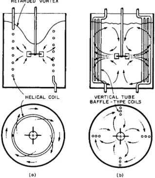
A n immersed coil in an agitated vessel for heat transfer is generally in one of two forms, the helical shown in Fig. 3 or the vertical baffle type depicted in
288 Vincent W. Uhl
FIG. 3. Agitated vessel with immersed helical coil for heat transfer. [After Oldshue and Gretton (01).]
FIG. 4. Agitated vessel with vertical baffle-type coils for heat transfer.
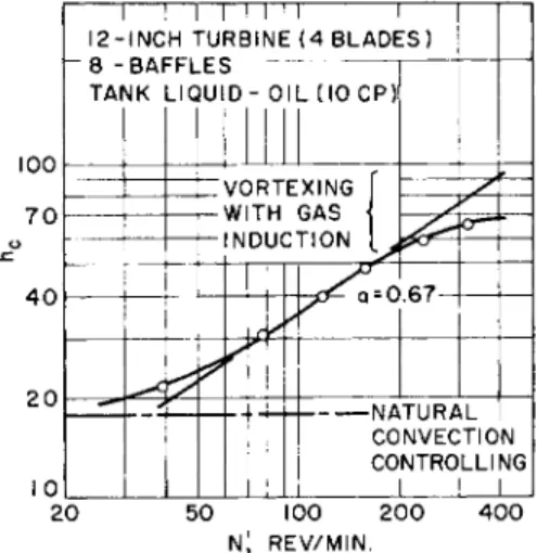
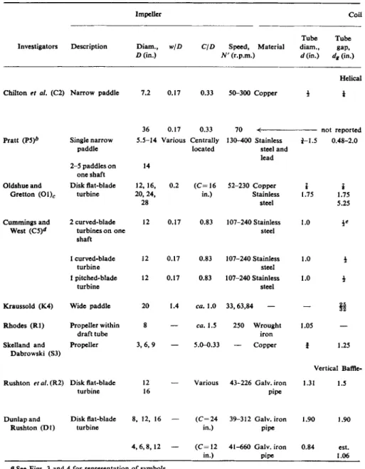
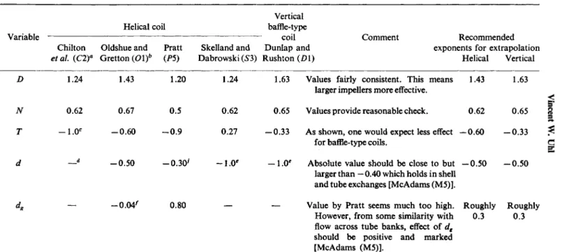
Fig. 4. The known heat transfer data for both forms of coils are summarized in Table IV. The manner of presentation of this subject takes into account b o t h t h a t there is n o over-all correlation of the available d a t a a n d there are fragments of information giving the effects of many variables which need to be summarized. The correlating equations of each separate work are tabulated in Table V. Here note that in general the Nusselt number used by Rushton and associates ( O l , D l ) is hcdjk, whereas that used by other workers is hcT/k, where d is coil diameter and Τ is vessel diameter. Table VI presents the re- ported and recommended effects of key variables which were included in the equations presented in Table V.
The range of test conditions in Table IV yields several items of special interest. The size range of vessels varies from 12 in. to 48 in. diam. with one point for a 60-in. vessel. Although Pratt's (P5) work embraced a wide range of dimensional variables, the unlikely values for some of the exponents in Eqs.
( 6 ) and (7) introduce some question concerning the advisability of using his
5. Mechanically Aided Heat Transfer 289
1 1 1 1 1 I 1 1 1 1 2 - I N C H TURBINE ( 4 BLADES)
" 8 - TAf
BAr MK
-hi.
LIC HJI D - O I L ( I O C P )
VORTEXING WITH GAS NDUCTION
à * VORTEXING
WITH GAS NDUCTION VORTEXING y WITH GAS NDUCTION VORTEXING WITH GAS NDUCTION
—
VORTEXING WITH GAS NDUCTION
—
= 0 67
£f— Q = 0
NATURAL CONVECTIO CONTROLLI 1 !
Ν NG N A T U R A L CONVECTIO CONTROLLI 1 !
Ν NG 2 0 5 0 100 2 0 0 4 0 0
n; REV/MIN.
FIG. 5. Plot of test data from Dunlap and Rushton ( D l ) which shows limiting heat trans- fer rates at higher speeds due to vortexing with gas induction and at lower speeds where natural convection is controlling.
can be overshadowed by free convection a n d with increasingly higher speeds the heat transfer rates will level off because of the induction of gas from vortex formation, as demonstrated in Fig. 6(a). This latter effect was noted by m a n y investigators. Vortices can be effectively minimized by the use of vertical baffle-type coils [Figs. 4 and 6(b)] or plate baffles (Fig. 3). Oldshue and G r e t t o n ( O l ) have shown t h a t the vertical baffle-type coil will have a value of hc 1 3 % higher than for a helical coil in a baffled t a n k at conditions of comparable power input. In this connection, Oldshue and Gretton report t h a t the baffle- type coil draws 7 5 % the power of the helical coil with plate baffles (Fig. 3) at the same impeller diameter and speed. This and other power information for systems with immersed coils are given in Chapter 3.
Some analogy can be drawn between the fluid regime with immersed coils and the shellside of baffled shell a n d tube heat exchangers. F o r the latter case the magnitude of the fluid velocity varies over a wide range with position in the shell a n d the velocity direction ranges from normal to parallel with the tubes.
F o r coils in vessels these velocity and direction range variations are indicated by the streamlines shown in Figs. 6(a) a n d 6(b). T h e i m p o r t a n t difference relations directly. Very little of the other work was directed toward finding the effect of dimensional variations. This is very apparent, from some of the studies (see Table V) where not even the coil tube diameter, d, was included in some of the correlations. Of the dimensional parameters only the effect of D, Γ, and to an extent, d, were indicated (see Table VI) and none could be considered t o be firmly established.
Figure 5 demonstrates that at low impeller speeds, the effect of agitation
290 Vincent W. Uhl
Impeller Coil
Tube Tube Investigators Description Diam., w/D C\D Speed, Material diam., gap,
Z>(in.) N' (r.p.m.) </(in.) <^(in.)
Helical Chilton et al. (C2) Narrow paddle 7.2 0.17 0.33 50-300 Copper i i
36 0.17 0.33 Pratt (P5)*
Oldshue and Gretton ( 0 1 )c
Single narrow paddle 2-5 paddles on
one shaft Disk flat-blade
turbine
70
5.5-14. Various Centrally 130-400 Stainless located steel and
lead 14
12,16, 0.2 ( C = 1 6 52-230 Copper 20, 24,
28
in.) Stainless steel
not reported 2-1.5 0.48-2.0
î
1.75
* 1.75 5.25 Cummings and
West (C5)<*
2 curved-blade turbines on one shaft
12 0.17 0.83 107-240 Stainless steel
1.0
1 curved-blade 12 0.17 0.83 107-240 Stainless 1.0 i
turbine steel 1 pitched-blade 12 0.17 0.83 107-240 Stainless 1.0 \
turbine steel Kraussold (K4)
Rhodes ( R l ) Skelland and
Dabrowski (S3)
Wide paddle Propeller within
draft tube Propeller
Rushton etal.(Rl) Disk flat-blade turbine
20 1.4 ca. 1.0 33,63,84 — 8 — ca. 1.5 250 Wrought
iron 3 , 6 , 9 — 5.0-0.33 — Copper
12 — Various 43-226 Galv. iron
16 pipe 1.05
Î 1.25
Vertical Baffle- 1.31 1.5
Dunlap and Rushton ( D l )
Disk flat-blade turbine
8, 12, 16 ( C = 2 4 39-312 Galv. iron in.) pipe
1.90 1.90
4 , 6 , 8 , 1 2 — ( C = 1 2 41-660 Galv. iron in.) pipe
0.84 est.
1.06
a See Figs. 3 and 4 for representation of symbols.
b This work embraces a wide range of size variables: 3 square tanks, 2 cylindrical tanks, 3 stainless steel coils, 2 lead coils, 10 sizes of single blade paddles, 15 arrangements of more than one 14 in. paddle and with varying paddle widths.
Table IV
Summary of Test Conditions—Heat Transfer to
5. Mechanically Aided Heat Transfer 291
Vessel
Test liquids Coil Coil Heating Type ( N o . o f test runs with each diam., height, Other D i a m . , Type and/or o f liquid where reported Dc (in.) Lc (in.) description Γ (in). Ζ IT bottom cooling tests given in parentheses)
Coils 9.6
7.75 5.75
18-28
Lower edge o f coil 12 0.83 Dished H + C Steady Water (21); A - 1 2 oil (12);
at same level as state 92 % glycerol (6); L M oil
bottom o f straight (11) side o f vessel C Batch Water (5); A - 1 2 oil (5)
60 0.83 Dished C Batch Water (1) Square ( Z = 33-41 Flat C Steady Water; isopropanol
14, 18, 24 in.) state Cylindrical
18, 23.5 Coil centered in
vessel
35.1 34.2
24
24 24
13 31.5 31.5
23
23 23
15
Combination coil with alternate turns for heating and cooling Lower edge o f coil
2 in. above bottom of straight side o f vessel
Vertical helix
Type Coils
— 60 Each baffle c o n - sisted o f 4 sections o f pipe.
See Fig. 4.
— est. 30 Each baffle con- sisted o f 3 sec- tions of pipe.
— est. 15
48
30
30 30
40
21
48
24
1.0 Flat
1.0 Dished
1.0 Dished
1.0 Dished
ca. 1.1 ca. 2.5
( Z - 2 0 in.)
Dished Conical Flat
H + C Steady Water; turbine oil (0.4-400 state cp.)
Steady Water (5); toluene (5);
state isopropanol (1); ethylene glycol (2); mineral oil (4);
glycerol (4) Steady Water (1); toluene (1);
state glycerol (1) Steady Water ( 1 ) ; toluene ( 1 ) ;
state glycerol ( 1 ) ; ethylene glycol(1)
Steady Transformer oil state
Batch Water
Batch Water
1.0 Flat H + C Steady Water state
1.0 Flat H + C Steady Water; 2 oils (0.4-55 cp.) state
1.0 Flat H + C Steady Water; 2 oils ( 0 . 4 - 5 5 cp.) state
c Vessel equipped with four baffles, 4 in. wide (see Fig. 3).
d Test work also includes media consisting of solids suspended
e One coil gap, dg, opposite turbine was 3 in.
in toluene, and water-oil mixtures.
Immersed Coils, Helical and Vertical, in Agitated V e s s e l s0
292 Vincent W. Uhl
Investigators
Impeller
type Correlation
Eq.
no.
Range of
Chilton et al.
(C2) Pratt (P5)
Narrow hcT paddle ~~k
Paddles, Square tanks:
one to hj five on k one shaft
Helical coils
= 0.87(ΛΓΕ β)0 β 2(Λ^ρΓ)^(Κ/5)-0 14
39(ArRe)°-*(iVPr)o-3 ^
-te)'
(5) 300-4 x l O5
2 x l 04- 5 x l 05
Oldshue and Gretton (Ol)
Cummings and West (C5)
Cylindrical tanks:
^ = 3 4 ( ^B e) »5( i V pr) »a
= 0.17(JVEe)°e<
(r(i)"
(6)
0
ία3Γ
¥ = 0 . 1 7 ( ^ ) - ( ^r) » "turbine
2 _Waded" ¥ = 1 . 0 1 ( i VE e)0 6 2( i VP r) H ( ^ ) -0 14 turbines
1-curved- Same as above blade
turbine
1-pitched- Same as above except that value of Κ is blade 0.91
turbine
(7)
400-2 x l O5 (8)
(9) 2 x l 03- 7 x l 05
Kraussold (K4) Skelland and
Dabrowski (S3) Rushton et al.
(R2)
Dunlap and Rushton ( D l )
Paddle Same as Eq. (9)
= 0.345 (ΛΓ^)0·62 ( Γ / Ο0 2 Propeller hcd_
3 χ 1 0 M 05 (9a) 2 . 5 x l 05- 1 06 Vertical Baffle-Type Coils
Disk flat- (D = 16 heating, hc = 0.00285 NRe (10a) blade in.) cooling hc = 0.00265 i VRe (10b) 105-5 x 10s turbine (D = 12 heating, hc = 0.00235 ( J VR e) °7 (10c)
in.) cooling hc = 0.00220 (NRe)°7 (lOd) da t" X = 0'0 9(N* *) 0 65 33 "2 X 1 016 0
Table V
Summary of Correlations—Heat Transfer to Immersed Coils in Agitated Vessel
5. Mechanically Aided Heat Transfer 293
RETARDED VORTEX
(a) (b)
FIG. 6. Liquid motion patterns with: (a) helical coil, but with no baffles; (b) vertical baffle-type coils, adapted from Dunlap and Rushton ( D l ) .
between these related geometries is t h a t one would expect d a n d dg t o have a much greater influence on hc for coils because variations in d and dg affect the flow distribution through a n d a r o u n d the coil or the degree of bypassing, whereas for shellside, variations in d a n d dg do not affect the flow distribution a n d consequently hc to a marked extent. The analogy with shellside flow a n d the qualification of greater potential bypassing for a coil in a vessel were taken into account in making the recommendations in Table VI for the effect of d and dg on hc.
N o w the influence of the other factors which were not included in the cor- relations will be discussed.
Type of Impeller. Cummings and West (C5) demonstrated that when all test conditions are the same, a pitched-blade turbine gave heat transfer rates a b o u t 10% less than a curved-blade turbine.
Number of Impellers. Cummings and West were unable to discern any change in rate of heat transfer with two curved-blade turbines installed on the same shaft as compared with only one turbine. M o r e data are needed to estab- lish more definitely the effect of this variable.
Reverse Direction of Pitched Turbine. Cummings a n d West found that
Table VI
Comparison of Correlations—Heat Transfer to Immersed Coil in Agitated Vessels [Values tabulated are for χ in hc α (variable)*]
Variable
Helical coil Chilton Oldshue and Pratt etal.(C2)a Gretton {0\)b (P5)
Vertical baffle-type
coil Skelland and Dunlap and Dabrowski (53) Rushton (Dl)
Comment Recommended exponents for extrapolation
Helical Vertical D
Ν Τ
1.24
0.62 - 1 . 0e
1.43 1.20
0.67 0.5 -0.60 - 0 . 9
- 0 . 0 4 ' 0.80
1.24
0.62 0.27
- 0 . 5 0 - 0 . 3 0 ' - 1 . 0e
1.63 Values fairly consistent. This means 1.43 larger impellers more effective.
0.65 Values provide reasonable check. 0.62
— 0.33 As shown, one would expect less effect —0.60 for baffle-type coils.
—1.0' Absolute value should be close to but —0.50 larger than — 0.40 which holds in shell and tube exchanges [McAdams (M5)].
— Value by Pratt seems much too high. Roughly However, from some similarity with 0.3 flow across tube banks, effect of dg
should be positive and marked [McAdams (M5)].
1.63
0.65 -0.33
-0.50
Roughly 0.3
294 Vincent W. Uhl
d -d
dg
- 0 . 2 9 - 0 . 1 4
- 0 . 3 0 - 0 . 2 5 '
- 0 . 2 0 — 0.35 All values reasonable.
— 0.14' Comments in notes.
- 0 . 3 0 - 0 . 2 0
- 0 . 3 5 - 0 . 2 0
a These values also hold for Cummings and West (C5) and Kraussold (K4).
b Baffles present besides helical coil.
c Here Τ only used for dimensional consistency, not as a variable.
dO n l y one size coil used; therefore, d introduced only to provide dimensional consistency.
e Here d only used for dimensional consistency. Although two tank sizes were used, geometric similitude was closely approximated.
' A s interpreted by author from data in reference (Ol). However, in view of comment in text, exponent of —0.04 appears unlikely.
* From an interpretation by author of data by Oldshue and Gretton (Ol). They claim hc = Κ'" {μνΙμ)ηι where m varies from 0.2 for high viscosity to 1.0 for water tests. The higher figure of 1.0 is most unlikely and is probably due to strong natural convection effects for the water tests.
h Pratt's correlation, which is Eq. (6), would have satisfactorily correlated the data for higher viscosity fluids from Chilton et al. (C2) if a term for (μ„Ιμ)€ had been included.
'Dunlap and Rushton actually show hc a ^ / f t )- 0*4. However, according to published discussion ( D l )
The exponent of —0.30 for d was deduced as a reasonable value by Pratt (P5).
5. Mechanically Aided Heat Transfer 295
296 Vincent W. Uhl
reversing the rotation of a pitched-blade turbine m a d e no discernible differ- ence on hc.
Agitator Location. Pratt (P5) stated that, for a paddle, vertical displacement between the top and b o t t o m levels of the helical coil had no appreciable effect on the heat transfer coefficient. On the other hand, Rushton et al. (R2) demon- strated conclusively for a disk-type flat-blade turbine with vertical baffle-type coils that the optimum rate of heat transfer occurs when the impeller is located in the center of the coil. It is to be recalled from Table II that with jackets, the pitched-blade turbine was about 2 0 % more effective in an intermediate than in a low position. Obviously, the average circulation past the heat transfer surfaces and hence rate of heat transfer is better for intermediate positions.
Variation in Depth of Liquid. F o r variation of liquid depth from 33 to 41 in., Pratt found no variation in hc. These are the only known data on the effect of depth of liquid and certainly cannot be considered to be conclusive because of the narrow data range.
Shape of Tank. Pratt found that a " s q u a r e "2 t a n k with side dimension, /, gave 1 5 % better heat transfer rates than a cylindrical tank where the vessel diameter, Γ, was the same as /. This was explained by marked observed turbu- lence (baffle effect) for the square t a n k in contrast to practically uniform swirl produced in the cylindrical tank.
Two Insoluble Phases. The effect of the presence of mineral oil in water on the heat transfer rate for two curved-blade turbines run at 182 r.p.m. can be calculated from the data of Cummings and West to be as given in the accom- panying tabulation. The batch temperature was 122°F. for all cases. In the two-phase systems, oil was dispersed in water and water wetted the coil.
Vessel charge hc
Water 600
25% mineral oil, 75% water 360 75% mineral oil, 25% water 190
Mineral oil 60
Effect of Suspended Solids. F o r operating conditions similar to those for the two insoluble phases as noted above, Cummings and West report the data given below for an ion-exchange resin of 16 to 50 mesh suspended in toluene :
Solids content (%) 0 9.8 24.8
hc 291 219 208
2 Often the qualification "square" is applied to a cylindrical tank, where the liquid height, Z, equals the tank diameter, T; viz., Z/T = 1.0. As used above, "square" connotes a vessel having a horizontal cross section which is square in shape.
5. Mechanically Aided Heat Transfer 297 3. Heat Transfer to Particles in Fluids
Hixson and Baum (H3) measured the heat transfer coefficient between liquid and solid phases of the same material in a series of geometrically similar agitated vessels by putting frozen pieces into the liquid and observing the rate of melting. Materials were water, benzene, acetic acid, and nitro- benzene and approximately 1-in. cubes, blocks, and cylinders were used. The vessel size ranged from 6 to 24 in. with a single run in a 47-in. i.d. vessel. The agitator was a pitched-blade turbine, where D = T/3, rotated at speeds from 200 to 400 r.p.m. Reynolds numbers ranged from 2 χ 104 to 106. Based on a method of calculation which allowed for the reduction in size of the melting solids, the data were correlated by
This relation did not correlate the data as well toward the end of a run as at the beginning, probably because of the change in particle shape from the assumed original shape as the process continued.
Hixson and Baum point out t h a t the analogy between heat transfer and mass transfer is direct and therefore data for one process could be used to predict rates for the other.
4. Heat Transfer to Boiling Fluids
The effect of agitation in increasing boiling heat transfer coefficients over nucleate, transition, and film boiling ranges was investigated by P r a m u k and Westwater (P4). Methanol was agitated at 200 to 1000 r.p.m. by a 3-in. diam.
three-blade propeller located 1 in. above the heating element which was a f-in. diam. by 6-in. long horizontal steam-heated copper tube. Their results show that the agitation must be intense to produce even a slight improvement for nucleate boiling. However, speeds of 1000 r.p.m. increased the max- imum film coefficient at the critical temperature difference by 2 5 % and in film boiling speed had a noticeable effect, increasing the flux by up to 100%
at the m a x i m u m 1000 r.p.m. speed. A n interesting point is that agitation did not change the critical temperature difference, which was about 51°F.
B. PROXIMITY AGITATORS
When Metzner and Taylor (M3) rotated a disk-type flat-blade turbine in a viscous corn syrup and an aqueous solution of sodium-carboxy-methyl- cellulose ( C M C ) , they noted, and the photographs of the exposed surface would indicate, that only the material in the vicinity of the impeller was displaced or turned over to any practical extent. This reported information serves to emphasize that the less expensive, more convenient, nonproximity impellers cannot impel or turn over very viscous fluids for any significant (12)
298 Vincent W. Uhl
distance. This example makes evident the role of the slowly rotating, large area agitator, namely, to circulate high-consistency materials to all sections of a vessel by the only practical action, positive displacement. F o r heat transfer operations it is desirable that this displacement be most marked adjacent to the heat transfer surfaces, therefore, the need for the proximity agitator.
Blades which scrape the transfer surface are found to be necessary for the pseudoplastic types of non-Newtonian fluid, which have a flow behavior index3 less than 1.0, and for situations where material accumulates on or tenaciously adheres to the wall surfaces. Besides the proximity sweeping feature, the agitator must generally incorporate blade elements which circulate the bulk of the material to and from the wall essentially by displacement action. The sections below deal with these three functions which pertain to heat transfer to high-consistency materials: close-clearance sweeping, wall scraping, and bulk mixing.
1. Close-Clearance Sweepers
The most c o m m o n form of close-clearance sweeper and that for which data have been obtained is the anchor or horseshoe agitator as shown in Fig. 7. Other forms are the helical ribbon [see Fig. 2(i) in Chapter 3] and the full helix, also called the helical screw, as is found in screw conveyors.
F o r the anchor, the known test conditions and sources are given in Table VII and the experimental data have been correlated satisfactorily by
(13)
FIG. 7. Jacketed vessel with anchor agitator.
3 For an explanation of the use of a flow behavior index to characterize non-Newtonian materials, consult Metzner (M2).
5. Mechanically Aided Heat Transfer 299 where Κ = 1.0; a = | for NRe from 10 to 300 (viscous regime)
Κ = 0.36; α = f for NRe from 300 t o 40,000 (turbulent regime).
This can be seen from the plot of the data in Fig. 8. N o t e that the test equip- ment listed last in Table VII is a flat-bottomed p a n dryer, for which the fluid depth is shallow (Z/T = 0.5). It can be seen from Fig. 8 that despite wide difference in geometries, the correlation used satisfactorily represents the data.
F o r each system tested, the clearance, C, was varied a n d the results unexpectedly show that the film coefficients for the c o m m o n range in practice, namely, CjD of 0.01 t o 0.03, are 20 t o 3 0 % less t h a n at smaller or somewhat greater clearances. N o t e that for the data of Brown et al (B4), CjD are 0.017 and 0.08 with 2 0 % better rate of heat transfer at the larger clearance. This p h e n o m e n o n is considered in detail by U h l a n d Voznick (U4). N o t e that t h e data were n o t obtained for values of CjD greater than 0 Ό 8 . However, at values of CjD greater than 0.08, h} would be expected to again decrease.
Almost all the work in the 23J-in. diam. kettle used by U h l a n d Voznick h a d a blade width of 2 in. However, a few runs made with a 3-in. blade showed n o measurable difference in t h e heat transfer rates, which is n o t surprising.
Published information for other close-clearance sweepers is extremely limited. Over-all coefficients are presented for several materials for straight ribbon, helical screw, plows, a n d varieties of the anchor in Tables VIII a n d I X . N o t e that the services listed in Table VIII are indirect drying, melting,
10
- 1 1 1 !
= _J_
INN I c ζ/τ
I I ! I Μ ! I I Ι I I I I I I I I I I Ι I f Ι Τ
Heating 1 1
or Cooling Reference
1 Mill.
y Ζ
: * 2 4 "
'/4
Η,
3/4" 1.2
H S C U H L 8k VOZNICK <U4) A s' 0 24" Vz" 1.2 Η β C U H L (U2)- Ο | 0 "
- · ΙΟ"
'/ν,'/ζ" 0.5
"/4".ΐ/2" 0.5 5" 0.75
" } U H L a VOZNICK (U4) -
- λ 60"
'/ν,'/ζ" 0.5
"/4".ΐ/2" 0.5
5" 0.75 C BROWN E T A L ( B 4 j ^ / <
=
• 00
Mr*
οΜ^β^-—- NOTE · BREAK IN CURVE
:
• · 0 C F V O X AT NRe = 3 0 0
"Ξ
• · 0 C
:
- ι ·ι ι ι I , ,Μ.Ι , 1 1 1 1 1 1 1 1 1 1 1 I I I 1 1 1 1 M 1 1 l l i I I I I I Γ
10 Ι Ο2 Ι Ο3 ΙΟ4 Ι Ο5
NR .
FIG. 8. Heat transfer correlation for anchor agitators (close-clearance sweepers). The solid line represents Eq. (13). Note that the data from Uhl (U2) and Uhl and Voznick (U4) are representative and not complete, and the manner of plotting does not serve to show vari- ation due to clearance, C, and heating versus cooling. The data from Brown et al. (B4) are for the 5-in. clearance only, which gave 18% better rates of heat transfer than with the 1-in.
clearance.
Table VII
Summary of Test Conditions—Heat Transfer with Anchor Agitator*
Impeller Vessel Diam.,
Investigator D (in.)
H/D w/D C/D
Speed, N' (r.p.m.)
Mat- erial
Diam., Τ (in.)
Z/T
Appur- , * tenances bottom .
in vessel
Heating and/or cooling
Fluid
Brown et al (B4)
49J ~ 0 . 8 8 0.06 0.08 40 Cast iron 60 0.7, 0.85
Hemi- Blowpipe spheric
C Sulfonation liquor μ = 20-200 cp.
58 ~ 0 . 7 6 0.05 0.017 40 Cast iron 60 0.70 Hemi- 6 in. baffle spheric plate hung
from cover
C As above
s
s
Uhl (U2) 22f 0.93 0.09 0.019 50, 75 Monel 2 3 i 1.26 Dished None H + C Bodied linseed oil; s cylinder oil.
μ = 100-10,000 cp.
i
Uhl and —22 J Voznick (U4)
0.93 0.09, 0.13
0.011-0.044 22-75 Monel 2 3 i 1.26 Dished None H + C Cylinder oil.
μ = 100-4000 cp.
Uhl and ~ 9 f Voznick (U4)
0.50 0.10 0.01-0.077 9-66 Steel 10i 0.50 Flat None H + C Cylinder oil.
μ = 100-4000 cp.
a See Fig. 7 for representation of symbols.
300
Table VIII
Over-all Coefficients for Close-Clearance Proximity Agitators
Speed Over-all
Type of agitator Charge Duty Shaft
axis
Agitator diam., D.
range N' (r.p.m.)
coefficient, U
Reference Helical screw,* solid flight type, Not specified Indirect drying6 Hor. 6-24 in. 2-20 2-12 Perry (PI)
jacket only —continuous 200 25-30
Helical screw, hollow-flight type Poor to wet Sensible heat Hor. c c 6-20 Perry et al. (P3) with jacket conductors transfer, granu-
lar to wet solids
Double-shaft helical screws, Sulfur ore Drying Hor. 70 mm. 1.9-20 3-34
hollow shaft with jacket. Sulfur ore Melting Hor. 70 mm. 0.6-20 0-49 Kasatkin et al. ( K l ) Blades of adjacent screws fit Sulfur Melting Hor. 70 mm. 1.5-20 6-55
into space between screws
Plows, T-blades Various, see references
Indirect drying
—continuous
Hor. 4-72 in. 4-140 5-50 Uhl and Root (U3) Anchor modification Various, see
references
Indirect drying
—batch
Vert. 36-96 in. 2-27 10-50 Uhl and Root (U3) Helical screw (screw conveyer) Wax distillate Crystallization
—continuous
Hor. 6 in. c 7-10 Nelson (N2)
Straight ribbon Wax distillate Crystallization
—continuous
Hor. 6 in. c 8-15* Nelson (N2)
None specified Wax distillate Crystallization
—continuous
Hor. c c 4-8
20 max.
Dunstan (D2)
a Screw conveyor design; also termed spiral conveyor.
b In indirect drying, the heat needed to vaporize the water or other liquid is transferred through a wall or barrier, as compared to so-called direct driers where the heat transfer media, usually air or combustion gases, are in direct contact with the surface of the material to be dried.
c Not specified.
d Using direct expansion of ammonia in the annulus.
5. Mechanically Aided Heat Transfer 301
Table ΓΧ
Comparison of Heat Transfer with Scraping vs. Close-Clearance* Agitation*
Operation
Double-motion agitation Av. diameter kettle—2.25 ft.
Material Character
of fluid
Viscosity range for test (cp.)
Speed of outer agitator—15 r.p.m.
Speed of inner agitator—25 r.p.m.
Initial Final Approx. increase condition condition in rate of heat Temp. hj Temp. hj transfer, scraping
(°F) (°F) over close (%) clearance Heating Medium motor oil Newtonian 10-100 Close clearance 100 32 210 24 14
30 p.s.i.g. Scraping 105 43 220 21
steam
Paraffin-base aircraft oil Newtonian 10-300 Close clearance 110 34 255 22 25
Scraping 110 55 252 27
Mixture of aluminum oleate Non-Newtonian 400-2500 Close clearance 110 9 265 1.6 500
and oil Scraping 120 13 260 13
Cooling Chocolate syrupc Assumed
— — —
50Newtonian
N o . 3 cup grease Non-Newtonian
— — —
400a For close clearance, clearance was 7/16 in.
* Data of Huggins (H5) essentially as summarized by Uhl and Voznick (U4)
c Essentially a sugar syrup.
302 Vincent W. Uhl
5. Mechanically Aided Heat Transfer 303 a n d crystallization (wax chilling). F o r indirect drying, the heat transfer mech- anism at the wall is essentially the same as for sensible heat change, however, the material experiences the consistency history from a slurry through a plastic mass to a free-flowing granular solid (U3). Often with crystallization and certainly with wax chilling, solids deposit on the wall a n d provide a more or less continuous resistance layer, which is sometimes limited by attrition.
N o t e that some of the data included in Table I X are for the scraping blades;
this subject is discussed in the next section.
2. Surface Scrapers
T w o types of scrapers attached to a sweep frame are shown in Fig. 9.
F o r hinged, follower-type scrapers, the value of the clearance, C, is a function
FIG. 9. Two typical scraper arrangements. Fluid pressure on the hinged-blade (a) forces the scraper to contact the container wall. Spring action forces blade (b) against the wall.
[From Uhl and Voznick (U4).]
of the fluid viscosity and the pressure exerted by movement on the flat sur- faces of the scraper. Scrapers in the form of spring-loaded flat or slightly helical ribbons are also used in small diameter (6 in. pipe) equipment operated continuously such as wax-distillate chillers and some crystallizers (see Fig. 10).
T h e V o t a t o r4 (Fig. 11) blades are of the "floating" type and are pressed t o the wall by a combination of centrifugal force and fluid kinetic pressure as the shaft revolves.
Huggins (H5) has clearly demonstrated t h a t scraping action is efficacious for very viscous and non-Newtonian materials. His work, which is summarized in Table IX, compared rates of heat transfer for various materials in a D o p p kettle equipped with a double-motion agitator b o t h with and without scrapers.
4 Registered U.S. trade-mark. Votator Division, Chemetron Corp., Louisville, Kentucky.
(a) (b)
FIG. 11. Cross section of Votator unit. Courtesy Votator Division, Chemetron, Corp., Louisville, Kentucky.
304 Vincent W. Uhl
: rh j r ET ι
I BACKER
^ ^ ^ ^ ^ ^ ^ ^
FIG. 10. Spring-loaded scraper for 6-in. pipe shell. Courtesy R . M . Armstrong Co., West Chester, Pennsylvania.
Τ l l l l l l l l l l l l l l i i l l l l T Physical arrangement of equipment
Concentric mounted shaft
5. Mechanically Aided Heat Transfer 305 Without scrapers the agitator might be considered to be equivalent to an anchor, but with good mixing of the entire charge. The clearance without scrapers was 7/16 in., which with an average vessel diameter of 2.25 ft. gives a clearance factor, C/D, of 0.016, which is within the clearance range that gives the minimum rate of heat transfer as noted in the preceding section. The improvement of the rate of heat transfer by the scrapers for the Newtonian fluids was one-seventh to one-half over the rates without scrapers, and as might have been expected, the use of scrapers enhances the rate of heat trans- fer to the non-Newtonian fluids (presumably pseudoplastic; flow behavior index less than 1.0) to a much greater extent, namely, four or five times.
Sufficient information for heating of viscous materials was found in the Huggins article to calculate roughly the film coefficients, hj9 for different temperature ranges. The initial and final values given in Table IX show that in all cases hj decreases as the temperature rises. The explanation may lie in a mitigated shear and reduced radial exchange of material (or mixing) with increased fluidity of the thin layer at the wall. The data from Huggins were also reduced to the correlation basis established for the anchor agitator data and plotted in Fig. 12.
The other scraper designs are long units with relatively small diameter which operate continuously. The only information available for equipment of the type shown in Fig. 10 is the common knowledge that for wax chilling, the over-all coefficients, £7, are in the range of 25 to 35 or over twice the values without scrapers as shown in Table VIII for this service.
The information for high-speed scrapers (Votator) is limited to Houlton
I T T T T T T T j —I I I I M111—I I I IIIIIJ—I I I IIIIIJ—I I I 11 lllj χ VOTATOR WATER HOULTON (H4)
• VOTATOR WATER (SINGLE PT) SKELLAND (S2) Ô NORSTRAPERS M E D I UM M 0 T 0R 0 il HUGGINS(H5)
« SCRAPERS /PARAFFIN BASE\ g i i r n M C,u, , Δ NO SCRAPERSUlRCRAFT OIL I HUGblNb IHDJ . SCRAPERS /ALUMINUM-OLEATEU .r r* (u*\ m
• NO SCRAPERS\0\L MIXTURE JHUGGINS (H5) %^ Ç ^%
NOTE: SOLID LINE IS CORRELATION FROM FIG.8 , EO. (13)
I Mill ι ι ι ι m i l n i l ι i n m i l ι ι 1 ι 1 ι ι ι ι ι II
IO"1 10° 10 I 02 I 03 I 04 I 05 I 06 NR e
FIG. 12. Comparison of scraping agitators with nonscraping (close-clearance sweeping) agitators.
![FIG. 3. Agitated vessel with immersed helical coil for heat transfer. [After Oldshue and Gretton (01).]](https://thumb-eu.123doks.com/thumbv2/9dokorg/1156573.83596/10.648.235.422.79.303/fig-agitated-vessel-immersed-helical-transfer-oldshue-gretton.webp)