SNAP T H E R M O E L E C T R I C SYSTEMS*
A. W. T h i e l e t and M. G. Coombs§
A t o m i c s I n t e r n a t i o n a l
A Division of N o r t h A m e r i c a n Aviation, Inc.
Canoga P a r k , California A b s t r a c t
In the r a n g e of m o d e r a t e e l e c t r i c a l power r e q u i r e m e n t s (approximately 1 kilowatt) t h e r m o e l e c t r i c power c o n v e r s i o n techniques offer m a n y a d v a n t a g e s in the design of n u c l e a r a u x i l i a r y power units for space application. The c u r r e n t t e m - p e r a t u r e capability of the lead t e l l u r i d e c l a s s of t h e r m o - e l e c t r i c m a t e r i a l s , in the vicinity of 1100°F, can e a s i l y be m e t with the d e m o n s t r a t e d p e r f o r m a n c e of the SNAP r e a c t o r
s y s t e m s . M i n i m u m s y s t e m weights a r e obtained at Carnot cycle efficiencies of the o r d e r of 25%, yielding a total s y s t e m efficiency of about 3%.
SNAP 10, a 300 watt s y s t e m is now under d e v e l o p m e n t . This s y s t e m will have the capability to withstand m i s s i l e launch e n v i r o n m e n t and a c c o m p l i s h c o m p l e t e orbital s t a r t u p .
I. Introduction
The d i r e c t c o n v e r s i o n of heat to e l e c t r i c i t y offers c e r t a i n distinct a d v a n t a g e s in n u c l e a r r e a c t o r a u x i l i a r y power u n i t s . T h e r m o e l e c t r i c c o n v e r s i o n t e c h n i q u e s a p p e a r to be p a r t i c u - l a r l y a t t r a c t i v e when used in conjunction with the d e m o n - s t r a t e d capabilities of the SNAP 2 r e a c t o r . T h e s e s y s t e m s can p r o v i d e
1) Static operation (no moving p a r t s )
2) Output independent of position with r e s p e c t to sun or e a r t h
3) Capability to withstand m i s s i l e launch and space e n v i r o n m e n t s
4) M i n i m u m h a z a r d during all p h a s e s of m i s s i l e launch and o p e r a t i o n
^ P r e s e n t e d at the Space P o w e r S y s t e m s C o n f e r e n c e , Santa Monica, California, S e p t e m b e r 27-30, I960.
Work done u n d e r AEC Contract: A T ( 1 1 - l ) - G E N - 8 t S N A P 10 P r o j e c t E n g i n e e r
§ S u p e r v i s o r , C o m p a c t P o w e r S y s t e m s D e p a r t m e n t
5) One y e a r or m o r e continuous o p e r a t i o n .
All of t h e s e a s p e c t s a r e i m p o r t a n t in the selection of an a u x i l i a r y power unit for s p a c e o p e r a t i o n . Static operation together with the independence of o r i e n t a t i o n r e d u c e the n u m - b e r of c o n s t r a i n t s on the vehicle stabilization s y s t e m with
consequent i n c r e a s e in r e l i a b i l i t y . The components of the s y s t e m will withstand the shock and vibration of m i s s i l e launch and will o p e r a t e without d e t e r i o r a t i o n from the s p a c e e n v i r o n m e n t . The r e a c t o r will be shut down throughout the a s c e n t p h a s e of the flight and will be s t a r t e d only after a successful orbit has been achieved. P r o p e r selection of the operating p a r a m e t e r s of the s y s t e m will enable it to provide a r e l i a b l e power s o u r c e for p e r i o d s of a y e a r or m o r e for long life space m i s s i o n s .
The s y s t e m c o n s i d e r e d h e r e will c o n s i s t of a r e a c t o r heat s o u r c e , a t h e r m o e l e c t r i c c o n v e r t e r , and a r a d i a t o r for heat r e j e c t i o n . As such, the b o i l e r , t u r b i n e , g e n e r a t o r , and c o n d e n s e r of a conventional power c o n v e r s i o n s y s t e m have been r e p l a c e d by the d i r e c t c o n v e r s i o n p a c k a g e . V a r i a t i o n s in the method of t r a n s f e r r i n g the heat between the components will be c o n s i d e r e d and the a d v a n t a g e s of the m e t h o d s s u m - m a r i z e d .
II. E n v i r o n m e n t a l A s p e c t s
The design of a space s y s t e m is strongly influenced by the e n v i r o n m e n t to which it is subjected. T h e s e effects in- clude the high vacuum, m e t e o r o i d s , and r a d i a t i o n as well as the m i s s i l e e n v i r o n m e n t . The s y s t e m m u s t p e r f o r m reliably, delivering the r e q u i r e d amount of power with a m i n i m u m weight and not subject the r e s t of the payload to an e n v i r o n - m e n t which would i n t e r f e r e with its p r o p e r o p e r a t i o n .
M i n i m u m weight is achieved by careful selection of the s y s t e m operating p a r a m e t e r s . The b a s i c components tend to have the following weight c h a r a c t e r i s t i c s :
1) R e a c t o r : The r e a c t o r m u s t have a c e r t a i n m i n i - m u m fuel inventory to p e r m i t o p e r a t i o n . In the r a n g e of e l e c t r i c a l power outputs c o n s i d e r e d h e r e i n , t h e r e is little i n c r e a s e in weight of the r e a c t o r with power r e q u i r e d . The SNAP Z r e a c t o r weight is a p p r o x i m a t e l y ZOO pounds.
Z) C o n v e r t e r : The c o n v e r t e r weight will be in the r a n g e of 10 to Z0% of the s y s t e m weight at low p o w e r s , and will v a r y in a p p r o x i m a t e p r o p o r t i o n to the e l e c t r i c a l power output.
3) Radiator: The radiator area is proportional to the thermal power to be rejected and inversely propor- tional to the fourth power of the effective radiating temperature. These two factor s are interrelated by the Carnot cycle efficiency term in the expression for the converter efficiency.
The parameters of the system must be selected to obtain a minimum weight. The thermoelectric converter is char- acterized by an efficiency which is very nearly a constant fraction of the Carnot cycle efficiency. Under this condition minimum radiator area is obtained when the heat rejection temperature is approximately 0.75 of the heat source tem- perature. This results in a Carnot cycle efficiency of 25%
and an overall conversion efficiency of 3% with typical present day thermoelectric converters.
Protection must be provided against damage to the system by meteoroids. In systems utilizing a heat transfer fluid the puncture of a line would result in rapid loss of the fluid to the vacuum environment. The thermoelectric materials in the converter can, in many cases, provide the protection r e - quired against this environment.
The semiconductor class of thermoelectric materials has been described as having the strength of plaster. This feature, together with difficulties in maintaining contacts, makes the converter potentially vulnerable to the shock and vibration of missile launch environment. Careful design of the supporting
structure has resulted in a demonstrated capability to with- stand shocks of 50 g on all axis and vibration in accordance with a typical vehicle specification.
Virtually all of the electronic payloads for space m i s - sions incorporate transistor circuits. The radiation sensi- tivity of these units establish the shield requirements. The wide variety of vehicle and payload configurations precludes any general statements in regard to the shielding require- ments, but the configuration of components about the reactor must be chosen so as to minimize scattering of radiation toward the payload.
III. Thermoelectric Converters
Minimum weight for the system would be obtained by operating the system at as high a heat source temperature as possible. The SNAP Experimental Reactor (SER) has demonstrated the capability of delivering 1200°F coolant on
a continuous basis·. It would thus be d e s i r a b l e to o p e r a t e the c o n v e r t e r a s close as p r a c t i c a l to this t e m p e r a t u r e and to develop the capability for higher t e m p e r a t u r e c o n v e r t e r o p e r - ation a s the r e a c t o r p e r f o r m a n c e is i n c r e a s e d . The life of t h e r m o e l e c t r i c c o n v e r t e r s using m a t e r i a l s such as lead t e l l u - r i d e may, however, b e c o m e a limiting factor when o p e r a t e d at 1200°F. Typical g e n e r a t o r s a r e c u r r e n t l y being o p e r a t e d at hot junction t e m p e r a t u r e s of 1000 to 1 1 0 0 ° F .
The s e m i c o n d u c t o r c l a s s of m a t e r i a l s p r e s e n t an a r r a y of p r o b l e m s to the successful o p e r a t i o n of a t h e r m o e l e c t r i c c o n v e r t e r . They m u s t be p r o t e c t e d both f r o m r e a c t i o n with surrounding m a t e r i a l s and f r o m t h e i r own d e t e r i o r a t i o n . T h e s e effects a r e t e m p e r a t u r e dependent and b e c o m e v e r y c r i t i c a l for m a n y m a t e r i a l s above 1 1 0 0 ° F . The d e t a i l s of the r e a c t i o n s that occur a r e beyond the scope of this p a p e r , but they include oxidation and sublimation of the t h e r m o - e l e c t r i c m a t e r i a l and r e a c t i o n and diffusion with adjacent m a t e r i a l s to change its t h e r m o e l e c t r i c p r o p e r t i e s .
The design of a c o n v e r t e r i n c o r p o r a t e s as m a n y f e a t u r e s as p o s s i b l e to prolong the life of the t h e r m o e l e c t r i c m a t e r i a l . A coating or j a c k e t is usually i n c o r p o r a t e d over the t h e r m o - e l e c t r i c m a t e r i a l to inhibit its sublimation and p r o t e c t it a g a i n s t the a t m o s p h e r e . In m a n y of the c o n v e r t e r d e s i g n s a spring is used to p l a c e the m a t e r i a l in c o m p r e s s i o n between its contacts in o r d e r that they be m a i n t a i n e d in spite of m a t e - r i a l r e a c t i o n s . T e m p e r a t u r e d r o p s a r e usually i n c u r r e d in t r a n s f e r r i n g the heat p a s t the spring to the heat r e j e c t i o n s u r - face. T h e s e combine with the t e m p e r a t u r e d r o p s in the e l e c - t r i c a l insulation and other heat l o s s e s in p a r a l l e l with the c o n v e r t e r to r e d u c e the efficiency c o n s i d e r a b l y below the p r e d i c t e d value.
IV. SNAP 10, A Conduction Cooled Low P o w e r System The SNAP 10 s y s t e m is a low power n u c l e a r a u x i l i a r y power unit utilizing t h e r m o e l e c t r i c c o n v e r s i o n . The c h a r a c - t e r i s t i c s of the SNAP 10 s y s t e m a r e given in T a b l e I.
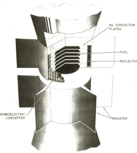
The s y s t e m c o n s i s t s of a conduction cooled r e a c t o r with a t h e r m o e l e c t r i c c o n v e r t e r mounted on its s u r f a c e . F i n s a r e used to provide an extended surface a r e a for heat r e j e c t i o n by radiation. The configuration of this s y s t e m is shown in F i g u r e 1.
The r e a c t o r is b a s e d on the SNAP 2 concept and u s e s s i m i l a r fuel and r e f l e c t o r m a t e r i a l . The low t h e r m a l power
r e q u i r e m e n t p e r m i t s heat to be r e m o v e d from the c o r e by conduction, t h e r e b y dispensing with a fluid and a s s o c i a t e d plumbing. The fuel m a t e r i a l is f a b r i c a t e d in the f o r m of c i r c u l a r p l a t e s which a r e stacked in a c y l i n d r i c a l a r r a y to f o r m the c o r e . B e r y l l i u m p l a t e s a r e placed between the fuel p l a t e s to i m p r o v e the t h e r m a l conductivity. The c o r e is r e - flected with b e r y l l i u m and clad in two c o n t a i n e r s to p e r m i t positive shutdown by s e p a r a t i o n of the two r e a c t o r h a l v e s . This r e a c t o r is 1Z inches in d i a m e t e r by 18 inches long.
Table I SNAP 10 S y s t e m
R e a c t o r U ^ - z i r c o n i u m h y d r i d e fuel, b e r y l l i u m r e f l e c t o r E l e c t r i c a l power output 300 watts
T h e r m a l power input 15 kw T h e r m o c o u p l e hot junction 1000°F
t e m p e r a t u r e
System weight 400 pounds
The s y s t e m is handled and t r a n s p o r t e d in a completely safe configuration with m e c h a n i c a l locks s e p a r a t i n g the two h a l v e s . T h e s e locks would be r e m o v e d from the r e a c t o r at an a p p r o p r i a t e t i m e in the countdown. The r e a c t o r would r e m a i n shut down through the launch sequence and would be s t a r t e d up on ground c o m m a n d after a successful orbit had been a c h i e v e d . A launch a b o r t could only r e s u l t in the s p r e a d of u n i r r a d i a t e d u r a n i u m which would not constitute a m a j o r h a z a r d .
The unit is placed in o p e r a t i o n by a s i m p l e m e c h a n i s m which d r i v e s the two r e a c t o r h a l v e s together to initiate the n u c l e a r r e a c t i o n . The unit c o m e s up to power and is self regulating by m e a n s of its negative t e m p e r a t u r e coefficient.
The s y s t e m p a r a m e t e r s p e r m i t o p e r a t i o n for p e r i o d s of one y e a r or m o r e without an a c t i v e control s y s t e m .
The weight of the SNAP 10 s y s t e m for varying power out- puts is given in F i g u r e 2. The r e l a t i v e weights of the v a r i o u s
s y s t e m components is shown in the s a m e f i g u r e . The s y s t e m weights a r e b a s e d on a hot junction t e m p e r a t u r e of 1 0 0 0 ° F . This t e m p e r a t u r e w a s chosen to i n s u r e r e l i a b l e o p e r a t i o n with p r e s e n t state of the a r t for t h e r m o e l e c t r i c c o n v e r s i o n . As i m p r o v e d higher t e m p e r a t u r e m a t e r i a l s b e c o m e available they can be i n c o r p o r a t e d in the p r e s e n t s y s t e m s with c o r r e s p o n d - ing reductions in the s y s t e m weight. In this operating
temperature range the radiation damage will not present a problem because of the annealing of lattice damage.
V. Forced Convection Cooled Systems
Due to the large surface area required for waste heat rejection and the limited amount of area available on the reactor, surface, the conduction cooled system described above is limited to relatively low power levels, probably
something less than a few hundred watts. For higher power systems the reactor heat must be transported to a separate thermoelectric generator which must provide sufficient radi- ating area to reject the appropriate amount of heat. The SNAP 2 and SNAP 8 are both high temperature liquid metal (NaK) cooled reactors and hence are ideally suited to be used in conjunction with a separate thermoelectric generator. In addition, the available exit temperatures of these two reactors are sufficiently high as to be able to fully exploit the tempera- ture capabilities of present day thermoelectric materials.
The performance of thermoelectric systems which use a SNAP 2 reactor coupled by means of a liquid metal heat transfer fluid to an integral converter-radiator is shown in Table II. The analysis assumes current converter state-of- the-art.
Table II Convection
Hot junction temperature Converter efficiency Power output
Reactor power (kw) Radiator area Weight
Reactor Shield
Converter radiator Misc. (pump, structure,
TOTAL Co
etc oled
.)
System 900°
10%
300 watts 12 kw 35 ft2 250 lb 250 100 100 700 lb
F of Carnot 1000 watts 35 kw 100 ft2
250 lb 300 300 150 1000 lb
200 400 POWER (watts)
600
Fig. 1. SNAP 10 Auxiliary Power Unit.
Be CONDUCTION PLATES
THERMOELECTRIC
CONVERTER RADIATOR
Fig. 2. Weight of SNAP 10 system (unshielded) v£
electrical power output.