Robust Crane Control
Ing. Marek Hičár, Ing. Juraj Ritók, PhD
Department of Electrical Drives And Mechatronics, Department of Design, Transport and Logistics, Technical University in Košice, Letna 9/B, 042 00 Kosice, Slovak Republic, Tel.: +421-55-6022268, 6022503
E-mail: hicarm@hron.fei.tuke.sk, juraj.ritok@tuke.sk
Abstract: The paper presents robust crane design by asynchronnous motor with frequency convertor at ensuring system robustness against load weight and rope length variation.
Exact position control and elimination of swinging in the final position are required too.
Firstly were assemblied mathematical models of main crane components: crab, bridge and uplift by real model of double beamed bridge experimental crane. Was designed robust control for defined interval variation of weight and rope length for real crane. Load weight and swinging are determined by estimators. Finally measured results gained on a laboratory crane are introduced.
Keywords: robust control, crane crab and bridge, uplift, poles region assignment method, observer, estimator, swinging model
1 Introduction
Control of main system drives control has to ensure the most effective and exact motion for crane crab, bridge motion and uplift. This control of crane crab and bridge includes two the most important conditions of exact motion trajectory and forbidden swinging in the final position. Crane systems using today keep precisious positioning but not elimination of the load swinging. Conditions have to be realized for different load weights and lengths of hanging rope. System robustness against change of load weight was designed by Ackermann’s by finding suitable feedbacks from robust areas which provides desired properties of the whole system. Rope length belongs to variable parameters what undertakes checking of control design for stability. Switching robust structure feedbacks (areas) for covering total tonnage and all rope lenghts was done by robust subareas which provide robustness against load weight and rope length variaton. Load swinging observer in crane crab and bridge direction were designed for reason of elimination electromechanical load swinging measurement for zero deviation control. Next, load weight observer identified real load weight on the crane hook which can vary between minimum (hook with tackle) and maximum crane
tonnage. All positive solutions of crane drives design are applied for real experimental bridge crane located at experimental laboratory Department of Construction, Transport and logistics at Technical University in Kosice. Load weight estimator was established for identification of real load for robust control.
Our tendency was approaching results from swinging model with measurement parameters what demostrates application of subsystem models in connection with real objects.
2 Poles Region Assignment Method
Poles region assignment method has ambition to get values of robust controllers (finding of load weight location in relation to rope lengths) where load swinging will be damped. Control design is procedure for finding feedback vector so that poles of characteristical polynom should be located in
Γ
- plane at parameters variation (load weight and rope length) (Figure 1). After matrix multiplying in formula (1) and comparison with right side will be expressed pair of robust controllers r1,r2, while
α
is generalized frequency.Graphical draw of r1 = f
( )
r2 at load weight changing helps to choose correct controllers parameters from areas of figures 3 and 5 [1, 2].Figure 1
Location of
Γ
- planeAckermann’s condition:
( ) ⎥
⎦
⎢ ⎤
⎣
=⎡
⎥⎥
⎥⎥
⎦
⎤
⎢⎢
⎢⎢
⎣
⎡
+
− +
− +
−
−
−
0 0 ...
3 2
1 0
...
4 4 3
2 1
2 3
2 2 2 2 2
1 2
3 2
2 3 2 2 2 2 2
2 1,r r a
n n
d a b
b
d a b
b b a b
α α α α
α α α
α α
α . (1)
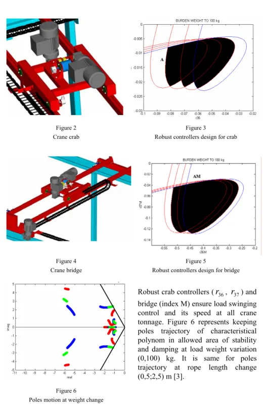
Figure 2 Crane crab
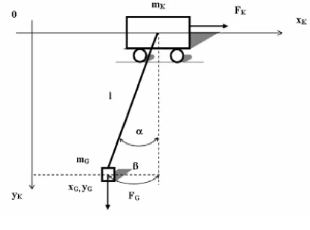
Figure 3
Robust controllers design for crab
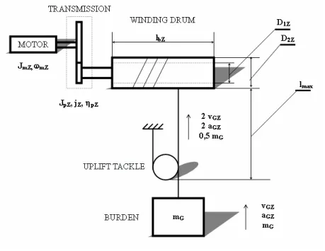
Figure 4 Crane bridge
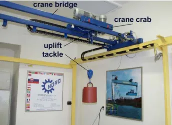
Figure 5
Robust controllers design for bridge
Robust crab controllers (
r
36,r
37) and bridge (index M) ensure load swinging control and its speed at all crane tonnage. Figure 6 represents keeping poles trajectory of characteristical polynom in allowed area of stability and damping at load weight variation (0,100) kg. It is same for poles trajectory at rope length change (0,5;2,5) m [3].Figure 6 Poles motion at weight change
3 Crane Crab and Bridge Model
Crane crab and bridge serve for load transport (separately or all at once) with weight
m
G from initial position xK1 to the final position xK2 [3].Figure 7 Crane rab and bridge model
Differential and algebra formulas for description of mechanical crane crab and
bridge part:mK x..K =FK +FGsin
α
, mG x..G =−FGsinα
, (2)α
.. cos
G G G
G y m g F
m = − , (3)
α sin l x
x
G=
K+
,y
G= l cos α
. (4)σ β
⎟⎟⎠
⎜⎜ ⎞
⎝
⎛ +
+
⎟⎟⎠
⎜⎜ ⎞
⎝
⎛ +
= +
1 1 1 1 1
1 1
2 3
2 1 2
2 2
2 2 ..
K K m
G y m
K K m
h K
m r
j p l J g m i m i m r
j p r J m
j L
x p ;
σ β β
g l m m m x
r j p i J r i m L j
p
KG
K K m y m K h
⎟⎟ ⎠
⎜⎜ ⎞
⎝
⎛ +
− + +
−
=
1 1
2
3
..2 2 1
2 2
..
. (5, 6)
Formulas 5 and 6 describe crab (bridge) acceleration
x
K ..and swinging acceleration
β
.. in its direction wherer
is transmission radius.α
is angle of swinging andβ
is transmitted angle to the meters.Figure 8 Load swinging observer with output
^
x6 and its speed
^
x7
Simulations in MATLAB Simulink on figure 9 and 10 are time respond of observer load swinging in crane crab and bridge direction. There was accepted maximum overswing in the final position 0.5 cm from practical reason by low toughness of hanging rope.
Figure 9
Load swinging in crab direction
Load swinging control in simulation model is ensured by feedback from load swinging
6
^
x
(x
6M^
) [m] and its speed
7
^
x
(x
7M^
) [ms-1]. On Figure 10 is observed zero swinging at the end of transport.
Figure 10
Load swinging in bridge direction
4 Crane Uplift Model
Figure 11 Crane uplift model
Torque formula and total moment of inertia for crane uplift:
dt J d M
MmZ GZ CZ
ω
mZ=
− , (7)
where
M
mZ - motor moment,M
GZ - load moment,J
CZ - total moment inertia,J
mZ - motor moment inertia,J
CbZ - drum moment inertia,J
CGZ - load moment inertia.Simulation of weight observer output provides real weight on the hook and this information is needed for robust controllers switching by defined subarea.
Figure 12
Weight observer with load weight output
On the Figure 13 is shown simulation crane bridge motion
x
5M [m] after sellecting robust controllers according to identified load weightm
G^
[kg]. Real rope length is gained from uplift model for next setting robust controllers.
Figure 13
Crane bridge trajectory and identified weight
5 Measured Processes at Experimental Bridge Crane
Bridge crane was experimentaly indentified by ARX model and was acquired linearized transfer functions of crab, bridge and uplift. Swinging in crab and bridge direction was identified by OE model. Robustness of real experimental crane model was ensured by switching structure of robust controllers for covering load weight and rope length variations.
Figure 14 Experimental bridge crane
Swinging sensor design consists of two each other perpendiculary rotary rheostats which measure deviation in crane crab and bridge direction.
Figure 15 Swinging sensor
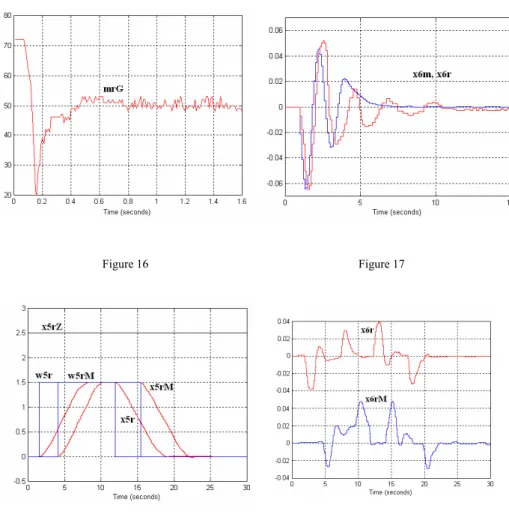
On the Figure 16 is shown identification of load weight
m
rG [kg] by estimator based on load uplift current. Figure 17 represents matching of real load swinging in crane crab directionx
6r [m] with swinging modelx
6m [m] which realized actuating signal to the control. Rope length is l = 1.1 m. Measured time responses on the Figure 18 is time response of contemporary crabx
5r and bridgex
5rMmotion at rope length l = 2.3 m. Load swinging is plotted on the Figure 19 at condition of zero swinging in the final position.
Figure 16 Figure 17
Figure 18 Figure 19
Project Experimental bridge crane was solved in cooperation with Department of Construction, Transport and Logistics and Department of Cybernetics and
Conclusions
Robust crane control as system with variable parameters was designed by Ackermann method of poles region assignment where by defined algorithm were obtain robust controllers for ensuring stability and damping at load weight and rope length variation in user range. Correct robust design was confirmed by measurement with included weight and model load swinging estimator at disallowed load swinging in the final reference position in crane crab and bridge direction.
Referencies
[1] Ackermann, J.: Parameter Space Design of Robust Control Systems, IEEE Trans. On Automatic Control, 1980
[2] Leonhard, W.: Control Of Electrical Drives, Springer Vlg., Berlin, 1985 [3] Hičár, M. : Written work to the academic dissertation exam, Robust crane
crab control, Košice 2001 (in Slovak)
[4] Ritók, J., Bigoš, P.: Automate crane in logistics system, In: International conference Logistics & Transport, Vysoké Tatry, 2001 (in Slovak)
[5] Y. Sakawa and H. Sano. Nonlinear model and linear robust control of overhead travelling cranes. Nonlinear Analysis, 30(4):2197{2207, 1997