TELSTAR SATELLITE POWER SYSTEM Robert E. D. Anderson* and Edward A. Hake*
Bell Telephone Laboratories, Inc., New York, N.Y.
and David Feldman*
Bell Telephone Laboratories, Inc., Whippany, N.J.
Abstract
The Telstar satellite was designed primarily to demonstrate the feasibility of putting an active real-time communication repeater into earth orbit. It was designed by the Bell
Telephone Laboratories Inc. and launched with the cooperation of NASA. In addition to the communications receiver and transmitter, the satellite contains several radiation experi- ments and a number of subsystems for acquisition and control.
The power drains for the various loads are operated on differ- ent duty cycles, reaching a peak load of about 2 W . The satellite power system design was constrained severely by requirements of long life (l to 2 years), minimum size and weight, and extreme radiation exposure. A solar cell, nickel- cadmium battery power system was selected, utilizing silicon n-on-p solar cells developed by the Bell Telephone Laboratories and special nickel-cadmium cells developed in cooperation with a battery vendor. Power conversion circuitry was de- signed to perform at maximum possible efficiency. The battery bus voltage variations were regulated to a common minus l6v bus by means of a solid-state regulator. High voltages for the traveling wave tube were obtained from this bus by means of a solid-state converter circuit. In view of the space and weight limitations, emphasis was placed on extremely reliable components and circuitry rather than on redundant systems.
Presented at the ARS Space Power Systems Conference, Santa Monica, Calif., September 25-28, 1962.
^Member of the Technical Staff, Power Systems Engineering Department.
I. Satellite Power Requirements
The Telstar satellite was launched on July 10, 1962. The launching vehicle was the three-stage Thor Delta, and the initial orbital parameters were 593-3 and 3501.8 nautical miles for perigee and apogee, respectively. The satellite's orbit was inclined to the equator at launch at an angle of Мк7°> and the orbital period was 157.8 min.
The satellite contains several experiments in addition to the communications receiver and transmitter. It also includes a number of electronic subsystems necessary for acquisition and control. The major items are listed below, with their power needs. No power conversion or regulation losses are included in the figures.
Communications experiment - 19"w, intermittent Microwave receiver
Microwave transmitter Microwave beacon
Radiation level experiments - O.lw, intermittent Proton particle detectors
Electron particle detectors
Radiation Damage Experiments - 0.2w, intermittent Transistors
Solar cells
Solar aspect indicator
VHF beacon transmitter - 1.8w, continuous Command receivers - 2.0w, continuous Telemetry system - 0.9"w, intermittent
The programming of these systems results in a power-drain profile having three major levels. The first is the con- tinuous drain of the VHF beacon transmitter and the command system, totaling 3-8w. The second includes telemetry, radi- ation level monitors, and the radiation damage experiments.
These require an additional 1.2w, and may be commanded "on"
by any of several ground stations. Finally an additional 19w for the communications experiment results in a peak load of 2 W , under control of a limited number of stations.
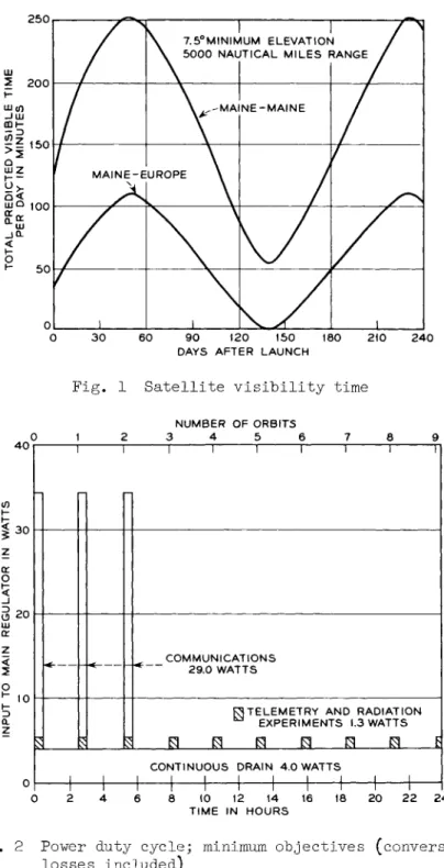
The communication experiments are of two types: those in which the station in Andover, Me. is used for simultaneous transmitting and receiving or for transmitting to the Bell Telephone Laboratories horn antenna at Holmdel, N.J., and those involving other stations, in Europe. Figure 1 shows curves of the predicted minimum daily visibility times for each type of operation for the stated conditions.
Early objectives for utilization of the satellite included monitoring telemetry and the radiation experiments for a minimum of 30 min per orbit and use of up to 30 min of com- munications time per orbit in at least three consecutive orbits. The power load profile shown in Fig. 2 illustrates the anticipated drain on the solar-cell, nickel-cadmium power plant for these minimum objectives. Actual initial satellite usage has been considerably greater, with four to six consecu- tive useful passes of 20 to 60 min duration being typical.
The flexibility provided by the command system has permitted maximum utilization of the satellite in accordance with the constraints described in Sec. IV.
It was expected that any or all of the experiments might have to be conducted while the satellite was eclipsed by the earth1s shadow. Figure 3 illustrates the predicted occurrence and duration of such eclipses, during the first 90 days after launch. The maximum eclipse period anticipated during the life of the satellite is ^5 min.
In addition to the magnitudes of the satellite power drains and their duty cycles, several other system requirements had a significant bearing on the power system design. They may be summarized as follows.
1) For the orbit desired and the launch vehicle available, it was recognized that every possible economy in weight must be achieved.
2) For simplicity and reliability, a spin-oriented satellite was dictated.
3) The satellite repeatedly would be exposed to the radi- ation of the Van Allen Belt.
k) A minimum useful lifetime of one year was desired, and twice that was hoped for. To be consistent with the size and weight limitations, emphasis was placed on highly reliable components and circuitry rather than on system redundancy.
II. Satellite Power System
A block diagram of the power system is shown in Fig. k.
The primary power source is a solar-cell plant. A sealed nickel-cadmium storage battery provides power for peak loads and for eclipse periods and is recharged regularly by the solar plant. The solar cells therefore are designed to pro- vide the average power requirements of an orbit, including battery losses. The battery is capable of absorbing the full solar plant output on a continuous overcharge basis.
The voltage of the paralleled solar plant and battery is in the range of 20.5 to 29.Ov, depending on the state of charge of the battery, the magnitude of the connected load, and the incident sunlight. The solar plant output is clamped at the characteristic overcharge voltage of the battery during light load periods.
Well-regulated d.c. power is required for optimum per- formance and maximum reliability of the electronic circuits in the satellite. The exclusive use of semiconductors, except for the traveling wave tube, made it possible to use a single solid-state regulator. It provides a well-regulated l6v at 91.5$ efficiency at peak load. The high potentials for the traveling wave tube are derived from the l6v with an unregu- lated solid-state converter.
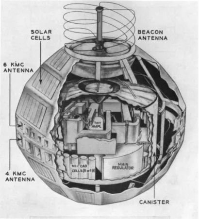
A cutaway view of the satellite is illustrated in Fig. 5«
It is nearly spherical in shape, having a height of 37 in. and a width of 3^-l/2 in. and weighing 17O lb. The solar cells, their mounting and protection contribute 26 lb. The battery weighs 11 lb., and the regulator and converter combined, including auxiliary control apparatus and wiring, weigh 7 lb.
The satellite is divided equatorially by the two microwave slot antennas. Each hemisphere of the satellite is divided into three different sections, each made with 12 facets, having angles of incidence of approximately 33°, 52°, and 68 with the satellite equator. The solar cell plant is distrib- uted over 55$ of the exterior surface and is made up of 50 groups of cells in parallel, each group containing 72 cells in series. A silicon diode is placed in series with each string to prevent cells that are not illuminated by the sun from loading the illuminated cells and also to prevent the battery from discharging into the solar cell plant. The cells are arranged on the surface of the satellite in a manner that provides nearly constant^ power regardless of the attitude of the satellite with respect to the sun. Neither pole of the
satellite is covered, to allow room for the launching attach- ment ring and the beacon antenna.
A typical module of 12 series-connected solar cells and a sealed nickel-cadmium cell are illustrated in Fig. 6. The satellite battery contains 19 such cells in series arranged in three groups of five cells each and one group of four cells.
The bell groups are spaced equally about the inner surface of the sealed electronic canister and are insulated by polyethyl- ene^ sleeves. The location of one group in the satellite is shown in Fig. 5- Advantage was taken of the reduced weight of the four cell group by locating it in the quadrant found to have the most weight, thereby assisting in obtaining a balanced moment of inertia of the satellite.
The location of the voltage regulator, which includes the low-voltage oscillator section of the converter, also can be seen in Fig. 5. The high-voltage section of the converter is located adjacent to the traveling wave tube, for which it supplies power. The major items of the satellite power plant are described in greater detail below, together with some auxiliary features.
III. Solar Cells
The solar cells used were developed by Bell Telephone
Laboratories and manufactured by the Western Electric Company.
Previous studies of the effects of radiation on solar cells have demonstrated that the short wave length performance is most important in determining the power output of solar cells after prolonged radiation exposure. To achieve an optimum solar cell and to provide long-life service in a radiation environment, n-on-p type cells were designed. The short wave length response (blue-green region) was improved by employing a shallow (0.25^ ) phosphorus diffused n-layer. To reduce resistive losses in the thin n-layer, the solar cells employ
"gridded" top contacts. The solar cells measure 1 x 2 cm x O.Ol· cm, including solder tinned areas, have five fingers on the top surface and use silicon monoxide as an anti- reflection coating.
Important in the design of a solar cell power plant for a communications satellite is a knowledge of the amount of power it can deliver after substantial exposure to the electron and proton radiation of the Van Allen Belt. The Telstar solar cell development program included extensive studies to determine l) the damage effects of electrons and protons of various energies, 2) the cell short-circuit current
under space illumination for a set of standard cells, and 3) correlation techniques to allow simple laboratory measurements.
The results of these studies have shown that long-life solar plant performance can be achieved by employing sapphire covers of thickness corresponding to O.3 g/стсг for front protection and a back protection of 1.0 gram. Figure 7 shows the pre- dicted performance of a typical Telstar solar cell compared to available p-on-n cells. This figure shows the efficiency and power output for each cell, based on an outer space illumination of 1^0 mw/cm as a function of the number of months exposure in the Van Allen Belt. The time scale shown is based on the solar cell response to electron and proton flux simulating Van Allen Belt exposure. The amount of protection described is considered sufficient to make the degradation due to electron flux negligible compared to the proton flux. It can be seen that the Telstar solar cell has a lower initial power output and efficiency than the blue-
sensitive p-on-n cell. However, the efficiency and power output remain higher, for longer periods, than the p-on-n cells.
It generally is accepted that the radiation levels of the Van Allen Belt are not known accurately and that values
quoted may be uncertain by perhaps a factor of 3 or even greater. Therefore, the time scale shown in Fig. 7 carries this same factor of uncertainty. One of the purposes of the Telstar experiment is to provide more data in this area.
However, it is expected that optimized n-on-p solar cells, when adequately shielded, are capable of providing a long- life power source for satellites subjected to long exposure to the Van Allen Belt.
The groups of solar cells used, consisted of specially tested and selected cells. Comprehensive investigations by means of spectral analysis and current, voltage and tempera-
ture measurements were made on individual cells.^ Modules of 12 series-connected cells were constructed of matched indi- vidual cells, which were then assembled in groups of six modules to form the 72-cell series connected string, as shown
in Fig. 5« Smaller groups of modules were used in the polar sections.
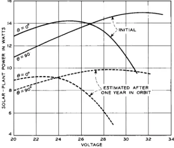
The performance of the solar cell plant was calculated for various angles of illumination and expected skin temperature distribution. The satellite is spin-stabilized, hence the skin temperature distribution is a function of its orientation with respect to the sun. Its spin rate is approximately 180 rpm, which is sufficiently high to insure a symmetrical
temperature distribution about the spin axis. For constant- sunlight orbits and polar illumination (O = 0°), calculated skin temperatures for the illuminated hemisphere range from +69°C at the polar band, to +13°C at the equatorial band.
The opposite or dark hemisphere has a calculated skin tempera- ture of -11^°C. For satellite equatorial illumination
(9 = 90°) ? "the skin temperatures at the polar and equatorial bands are -3° and +1°C respectively. Figure 8 shows the expected power available from the solar power plant as a function of plant voltage for polar and equatorial illumina- tion angles. Also shown is a pessimistic calculation of the expected change in power plant output after 1 year due to radiation in the Van Allen Belt.
The power available from the solar power plant will decrease continually due to proton radiation. However, it will be possible to utilize the available power by reducing the average energy requirements of the load by changing the duty cycle. This may be accomplished by ground command. Early and proper interpretation of the performance parameters by means of telemetered data will permit use of the satellite beyond the time when the solar plant is incapable of meeting the maximum energy requirements. The battery system will continue to operate satisfactorily as long as the solar plant is capa- ble of providing sufficient energy for recharging.
XV. Storage Battery
The sealed nickel-cadmium cells used in the Telstar satellite were designed and built by Bell Telephone
Laboratories, with a battery vendor providing the active cell elements. Each cell measures k.6 in. long, including the terminal and tubulation, and has a 1.3-in. diameter (l.5 i-n- at the flange). The cells each have a nominal capacity of 6 amp-hrand weigh 8 oz. A typical volt-ampere or Tafel characteristic for individual cells is shown in Fig. 9-
The cells were made with nickel cans and a ceramic seal.
Nickel has been found to be more resistant to caustic attack than cold-rolled steel and is relatively easy to weld with resistance welding techniques. A high alumina ceramic was bonded to a kovar pin and cover to provide an improved
ceramic-to-metal seal. The dry active elements were inserted in the can and the cover resistance-welded to the case. In this manner the cell could be welded carefully to insure that no cracks or holes were created in the vicinity of the weld. Each cell was leak-tested by surrounding the cell with helium, evacuating the cell through a tubulation, and
analyzing the evacuated gases, looking for helium. Then the proper amount of electrolyte was added through the tubulation and the cell Ъаск-filled with a mixture of oxygen and helium.
The tubulation was then pinch-sealed and resistance-welded.
The tubulation was finally leak-tested by a helium sniff test.
All cells were subjected to extensive electrical tests, including measurements of capacity, overcharge characteris- tics, repeated cycling, self-discharge rate, and internal resistance. In addition, environmental vibration and acceleration tests were performed. From a group of several hundred cells, sufficient to provide extensive test and reliability information, batteries of 19 cells were made up of individual cells having essentially matched character- istics. Experimental studies also involved thermal cycling, high overcharge, and repeated charge-discharge cycles on a limited number of cells. Prior to the launch date, approxi- mately 500,000 cell-operating hours had been accumulated, providing reasonable confidence that the 19-cell battery would meet the satellite objectives. The power system was designed to operate with maximum loads and the minimum voltage limit of an l8-cell battery. The battery has one extra cell for series redundancy.
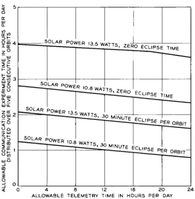
The use of the satellite for communication and radiation experiments is governed by the average solar power over a 2^--hr interval, the orbit eclipse period, the battery state- of-charge, the allowable battery depth of discharge, and the probability of the satellite being eclipsed at the time an experiment is conducted. To provide a flexible experimental program involving communication experiments of varying du- ration, the technique of analyzing the energy flow equations for the battery was employed. The energy removed from the battery must be returned whenever the solar plant is capable of supplying more power than the load requires. The battery energy flow technique correlates the charging energy available from the solar power plant over a 2^--hr period with the energy requirements of the satellite electronic packages. This analysis allows the power system designer to account for different battery depths of discharge in establishing satel- lite utilization. Fig. 10 shows the usable total time for communications experiments distributed over five consecutive orbits, as a function of the total time spent telemetering data to various ground stations. The effect on useful
experimental time of decreased available solar power and orbit eclipse time is evident for the case of a maximum battery depth-of-discharge of kofi. Families of such curves were
developed for different values of available solar power, orbit eclipse time, and battery depth of discharge.
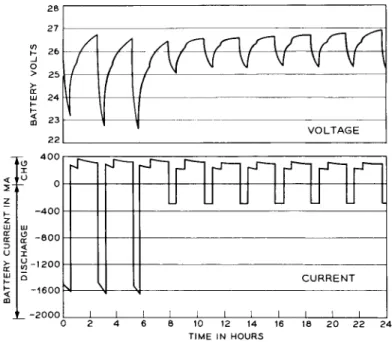
The performance of the entire satellite power system was demonstrated in a variety of laboratory tests employing a simulated solar cell plant, which included the effects of changes in solar cell and battery temperature, available solar power, depth-of-discharge, and eclipse time. Extensive tests were conducted to determine the effects of battery charging in periods of constant satellite illumination and in maximum eclipse orbits. Figure 11 illustrates profiles of battery current and voltage, for the extreme condition where eclipse periods coincide with the intermittent load profile of Fig. 2. Certain of these tests were run continuously for periods in excess of one year, and all tests indicated satis- factory performance.
V. Regulator
The main regulator provides minus l6v, regulated to ±1$
short-term and ±2% long-term. It must compensate for the range of voltages available at the battery and the variation in load illustrated in the load profile of Fig. 2. It was designed to operate in an ambient temperature range of 25° to 95°F in orbit. A minimum-loss design was of prime importance.
An efficiency of 91-5$ a"t peak load conditions, and 80 to 88%
at light loads was achieved.
There are two outputs from the regulator. One output is connected to the input to the traveling wave tube power supply, through a filter choke, to minimize the feedback of unwanted ripple produced at the 2.5 kc converter switching rate. The remainder of the electronic loads are connected through an additional filter section. The ripple at this output is less than 1 mv, rms.
The components of the regulator are mounted on irradiated polyethylene boards, filled with glass cloth. Transistors and diodes requiring heat sinks are mounted on beryllium oxide boards, connected thermally to the canister to obtain maximum heat transfer with a minimum of size and weight. To control radiation effects, all germanium transistors were shielded by a l/8-in.-thick aluminum cap, supplementing the shielding provided by adjacent apparatus, the canister and the outer shell of the satellite.
VI. Traveling Wave Tube Supply - d.c. to d.c. Converter The d.c. to d.c. converter furnishes heater, anode, helix and collector voltages for the traveling wave tube, derived from the regulated l6v supply. The converter is unregulated, and its output regulation is the sum of the changes in the l6v supply and the voltage changes due to load variations in the traveling wave tube. The load changes result from long- term changes in operating points. The overall efficiency of the converter is 70$. A simplified diagram of the converter is shown in Fig. 12. The figure also shows the requirements of the several outputs.
To conserve power, the converter is energized only during the communications experiment. Sequential application of the traveling wave tube voltages by ground command is accomplished by use of three magnetic-latching relays shown in Fig. 12.
Relay A connects the oscillator section of the converter to the l6v regulator, energizing the traveling wave tube heater.
Relay B is operated less than a minute later, applying the helix and collector voltages. A minimum of 3 min after the heater voltage is applied, the C relay is operated, and the anode voltage is applied. Potentials are removed in the reverse order. This procedure was adopted to insure maximum tube life, at the expense of reduced converter efficiency and increased weight and size. The use of several separate transformers for the traveling wave tube potentials permits the use of reliable low voltage relays in the transformer primaries.
The low voltage or oscillator portion of the converter uses novel circuitry to achieve maximum circuit efficiency. This section produces a square ac wave with a nominal frequency of 2.5 kc at transformer Tl. The apparatus in this section is mounted integrally with the regulator, at a distance from the traveling wave tube.
Transformers T2 and T3 convert the low voltage at trans- former Tl to the higher potentials of the anode, helix and collector. The accelerator and helix d.c. potentials are developed and filtered by voltage doublers. The collector d.c. voltage is derived from a conventional bridge circuit and a capacitor filter. A wide range of adjustment of the transformer secondary voltages is available to obtain optimum performance of individual traveling wave tubes.
Due to the need for application of the heater voltage in advance of the helix, collector, and anode voltages and the
requirement of a wide range of heater voltage adjustment, a separate transformer Th is provided. To minimize the losses in the heater circuit and to improve regulation, a synchronous- transistor rectifier arrangement is used to derive the d.c.
heater voltage.
The transformers and the rectifying and filtering apparatus for developing the traveling wave tube voltages are located in a shielded container adjacent to the traveling wave tube to reduce the high voltage wiring in the canister to a minimum.
VII. Two-Year Timer
To eliminate the possibility of VHF interference in the event ground command capability is lost, an electromechanical timer has been installed. Its function is to remove the satellite VHF beacon irrevocably at the end of two years in orbit. It consists of an electronic movement and a precision gear train to operate a switch after two years of operation.
It is equipped with electronic components selected to minimize radiation effects. A means of starting the timer just prior to launch is incorporated. A button-type mercury cell pro- vides the power to drive the timer. The mercury cell was selected for its small size, constant-voltage discharge characteristic, and retention of capacity over long periods of discharge at very low rates. The complete timer weighs approximately 0.5 lb.
The beacon may also be deactivated by ground command any time prior to 2 years.
VIII. Battery Discharge Gate
As illustrated in Fig. 5^ the sealed canister containing the electronic equipment is mounted within the satellite shell, restricting all access to the canister. For reliability, the battery discharge lead was not brought out to the outer shell.
Since, the continuous loads were connected to the battery and solar plant internally at the time of final assembly, a means for remotely disconnecting the battery was required to facili- tate ground tests. This arrangement is used also for limiting battery discharge in orbit, under emergency conditions.
A silicon diode, poled to prevent battery discharge, was installed as a gate in the negative discharge lead of the battery, as shown on Fig. k. It normally is bypassed by a
contact on the S relay, under control of the command receiver.
Although the diode may at times be used to prevent discharge
of the battery, the battery still may be charged by the solar plant or the power supply furnished for ground tests of the
satellite. The gating diode may be used for the following purposes.
1) To block discharge of the battery between ground tests or during shipment, when no charging current is available.
2) To isolate the battery during ground test or in orbit, when telemetry data indicates an excessive discharge of the battery.
3) To isolate thq battery by command while the satellite is in a temporarily unfavorable orientation. This could occur during an extended period of polar illumination, after the solar plant output had been reduced by radiation or other damage.
k} To isolate automatically the battery when the low- voltage battery cutoff circuit is triggered. This circuit
acts in an emergency to prevent damage to the battery if the heavy-drain communications experiments are not disconnected at the end of a pass.
IX. Ground Power
Nearly all of the satellite prelaunch tests required an auxiliary power source to charge the nickel-cadmium battery, since the solar plant was inactive. An extremely reliable and foolproof arrangement was required, due to the extreme vulnerability of the battery on overcharge and the knowledge that different operators would be involved at the several assembly, test and launch sites. An additional design problem was the variation in loop resistance of the leads between the supply and the satellite, which ranged from as much as 7 ohm at the launch site to practically zero at other test areas.
To meet these requirements, a rectifier was designed which uses a passive ferroresonant circuit to regulate only for
input voltage variations. A relatively high rectifier output resistance was provided. Under peak satellite loads, the satellite battery furnishes part of the load current. Under all other load conditions the battery is on charge, but the high rectifier output resistance limits the charge current to a safe value as the battery reaches its overcharge voltage.
The differences in power loop resistance at the various sites were equalized by "padding out" to the desired total rectifier output resistance.
X. Telemetry
Because of the experimental nature of the Telstar satellite, 115 telemetry channels are monitored at a 1 frame/min rate.
Of these, 26 channels are associated directly with the power system, and information from four additional channels is necessary to determine the operational state of the satellite.
The telemetry data is used to provide a basis for utilization of the satellite, as well as to monitor the performance and temperature of critical apparatus and circuits.
The telemetry equipment is arranged to accept d.c. signals of a maximum of 'yv in the standard channels and a maximum of 0.5v on the sensitive channels. A sensitive channel is used for the current data due to the low voltage drop of the current sensor. The overall accuracy of the telemetry data is ±2$, including transmission.
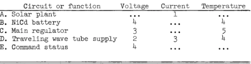
The channel assignments associated with power sections are given in Table 1.
Table 1 Assignment of telemetry channels Number of Channels
Circuit or function Voltage Current Temperature A. Solar plant ... 1 ...
B. NiCd battery k ... k C. Main regulator 3 ••• 5 D. Traveling wave tube supply 2 3 ^ E. Command status k ... ...
The nine channels assigned to the battery and the solar plant are of particular importance in programming utilization of the satellite. Orbital measurement of the solar plant current and the battery temperatures and voltages, coupled with prelaunch ground measurements of the drains of the electronic circuits for the various command conditions, make possible reasonable estimates of the state of charge of the battery.
XI. Performance
The performance of the power system to date has agreed very closely with the design objectives. The average solar plant output measured shortly after launch was about 13.lw. This represents an error in calculation of only about 2$, con-
sidering the fact that the solar distance at launch time pro- vides a solar intensity about 3% less than mean value. No
solar plant damage was incurred during launch.
The precise accuracy of the launch vehicle and guidance system resulted in an initial extended period in full sun- light. This permitted continuous operation of telemetry, as well as up to six periods per day of communications experi- ments.
Even with maximum utilization, the battery voltage range has been within 23.6 to 28.6v, and battery temperatures in the range 65 to 77°F. The power conversion equipment has per- formed perfectly in an ambient approximating the battery temperature.
As of this writing (September 1, 1962} the Telstar satellite has completed nearly 5OO orbits in 52 days. The radiation experiments have provided a great deal of information on the magnitude and effects of the Van Allen Belt. The traveling wave tube has been operated successfully over 200 times for a great variety of communications experiments.
The solar plant output current has been logarithmically degraded by radiation to about 88$> of its initial value.
Barring a catastrophic failure, the satellite power system should provide adequate power for experiments for many more months. On the basis of the in-orbit data, it is now esti- mated that the solar current after two years will be about 70^ of its initial value.
References
1 Smits, F.M., Smith, K.D., and Brown, W.L., "Solar cells for communications satellites in the Van Allen Belt," Journal British Institute Radio Engineers 22, l6l (1961)•
2 Smits, F.M., Rosenzweig, ¥., and Brown, W.L., paper for Solar Working Group Conference, sponsored by Inter-Agency Advanced Power Group, Washington, D.C.j February 27, 1962 (to be published).
3 Early, J.M., "N-on-P solar cells for the Telstar satellite,"
American Institute Electrical Engineers Energy Conversion Conference (August 1962}.
Cuttriss, D.B., private communication, Bell Telephone Laboratories (January 1962}.
250
90 120 150 180
DAYS AFTER LAUNCH 240
40
30
o
_l
20
z <
O
Fig. 1 Satellite visibility time
NUMBER OF ORBITS 3 4 5 6
10 D
z
1
г^—r
N t
1
г — 1
{ 1
1 1 1 1 1 1 1
1 COMMUNICATIONS
"p ~ 29.0 WATTS
R3 TELEMETRY AND RADIATION
^ EXPERIMENTS 1.3 WATTS
3 H H H H H H Б
CONTINUOUS DRAIN 4.0 WATTS
1 1 1 1 1 1 I I l l I
1 1 1 1 1 1 1 1 1 1 1 1 8 10 12 14 16 18 20 22 24
TIME IN HOURS
Fig. 2 Power duty cycle; minimum objectives (conversion losses included)
30 45 60
DAYS AFTER LAUNCH 90
F i g . 3 S a t e l l i t e e c l i p s e time
SOLAR PLANT
VOLTAGE LOW BATTERY CUTOFF
BATTERY DISCHARGE
GATE
RELAY S
NLCd 19 CELLS
2 YEAR TIMER
COMMUNICATION CIRCUITS
3.2W
TELEMETRY 0.9 W
RADIATION EXPERIMENTS
0.3 W
VHF BEACON 1.8W
COMMAND RECEIVER AND DECODER N0.1
1W
COMMAND RECEIVER AND DECODER N0.2
1W
Fig. k Block diagram of power system
BEACON ANTENNA
4 KMC ANTENNA
CANISTER
Fig. 5 Cutaway view of Telstar s a t e l l i t e
Fig. 6 Telstar nickel-cadmium c e l l and solar c e l l module
1 1 1 CELL SIZE I X 2 C M
FRONT PROTECTION 0 . 3 G M / C M2 BACK PROTECTION 1.0 G M / C M2
OUTER SPACE ILLUMINATION 140 M W / C M2
0.01 0.1 1.0 10 TIME IN MONTHS IN THE VAN ALLEN BELT
Fig. 7 Telstar N-on-P cell compared to standard P-on-N cells
26 28 VOLTAGE
Fig. 8 Solar plant output as a function of battery voltage and illumination angle
1.60
o >
Z i.50
<
O >
U 1.40
1.35
CELL NOMINAL CAPACITY 6.0 AMPERE HOURS
^ 4 5 ° F ^ ^ 1 5
/<fr
>F ^ ^ 0 °
^ 5 0 ° F F 70° F
100° F
120°F
10 2 0 4 0 60 100 2 0 0 4 0 0 600 1000 2 0 0 0 OVERCHARGE CURRENT IN MILLIAMPERES
Fig. 9 Telstar nickel-cadmium cell characteristics
Ш or </) О Ш 4 D t
?° Ш
Ш >
IP
2o
Ш Ш О Ш 2
5°
l5
uj Q _i CD
<
O
d ° <
SOLAR PQWER t 3.5 , J „r r | | | I
SOLAR POWER
iSUilUlifRoecL,
SOLAR POVVFP i 4 I
^ O L A R j D Q W E R
pS E TIME
^ Í I I ^ M I N U T E
0 4 8 12 16 2 0 2 4 ALLOWABLE TELEMETRY TIME IN HOURS PER DAY
Fig. 10 Allowable satellite utilization
l/' /1
1 1
/
л
V
// V V V V V V \
\\
1
' VOLTAGE
1200
Н
CURRENT8 10 12 14 16 18 2 0 22 2 4 TIME IN HOURS
Fig, 11 Battery voltage and current for a 2^-hr period
1 16V D C - T O - D C CONVERTER
D C - T O - A C INVERTER
^тжж
\—<8h
c
RELAY B
♦ ® -
^шк^-
RECTIFIER FILTER AND
LOW-VOLTAGE SECTION
RECTIFIER FILTER AND
RECTIFIER FILTER AND
RECTIFIER FILTER AND
AC TO DC (HIGH VOLTAGE) CONVERTER SECTION
ANODE 1800 VOLTS
0.4 WATT
HELIX 1500 VOLTS
0.4 WATT
COLLECTOR 750 VOLTS 13.5 WATTS CATHODE
0 VOLTS
HEATER 4.5 VOLTS 1.5 WATTS
12 Block diagram of d.c.-to-d.c. converter and travelin wave tube