Porous sandwich ceramic of layered silicon nitride-zirconia composite with various multilayered graphene content
K. Bal azsi
a, M. Furk o
a, Z. Liao
b, J. Gluch
b, D. Medved
c, R. Sedl ak
c, J. Dusza
c, E. Zschech
b, C. Bal azsi
a,*aCentre for Energy Research, Hungarian Academy of Sciences, Konkoly-Thege Str. 29-33, 1121, Budapest, Hungary
bFraunhofer Institute for Ceramic Technologies and Systems IKTS, Maria-Reiche-Str. 2, 01109, Dresden, Germany
cInstitute of Materials Research, Slovak Academy of Sciences, Watsonova 47, 040 01, Kosice, Slovak Republic
a r t i c l e i n f o
Article history:
Received 31 December 2019 Received in revised form 23 February 2020 Accepted 27 March 2020 Available online 5 April 2020
Keywords:
Sandwich structure Porous ceramic Si3N4-ZrO2
MLG
Hot isostatic pressing Multilayered graphene
a b s t r a c t
The influence of the various content of the multilayered graphene (MLG) on the structural and me- chanical properties of thefinal bulk porous silicon nitride-zirconia (Si3N4-ZrO2) based ceramics was investigated. The ceramic composites were prepared in the form of the laminated structure with different (5-30-5 wt% and 30-5-30 wt%) MLG content by hot isostatic pressing. Homogeneous distri- bution of the MLGs, a completed phase transition fromatob-Si3N4in case of 5 wt% MLG have been observed. The structural examinations revealed that the multilayered graphene and zirconia particles owing to their different sizes and shapes influenced the porous microstructure evolution and the related mechanical properties of the composites. The sandwich structures enhanced the mechanical properties compared to reference ceramic with 30 wt% MLG. The position of the layer with higher graphene con- tent, high ratio ofa/bphase of Si3N4and higher porosity had crucial effect on thefinal mechanical properties.
©2020 Elsevier B.V. All rights reserved.
1. Introduction
The silicon nitride (Si3N4) is the widely used high-temperature ceramic material (up to 1500 C) [1]. Due to it’s extreme high hardness and toughness in a wide range of temperatures, potential applications include reciprocating engine components, turbo chargers, bearings, metal cutting and shaping tools as well as hot metal handling. Silicon nitride has better mechanical properties at high temperatures compared to most metals, and it’s low coeffi- cient of thermal expansion (CTE) results in a higher thermal shock resistance than for most ceramic materials. However, owing to the intrinsic brittleness of ceramic materials, it is important to improve their strength and toughness, and consequently the reliability needed, for specific use cases [2e6]. Nanofillers added as rein- forcing agents to the ceramic matrix can improve mechanical, electrical and thermal properties of the final materials. These nanofillers can also provide extrinsic toughening mechanisms [7e11]. The most promising filler materials are graphene,
multilayered graphene (MLG) or graphene oxide (GO) owing to their outstanding mechanical, electronical, physico-chemical and mechanical properties [12e14]. The addition of graphene to a ceramic matrix can increase it’s thermal conductivity, which is an essential advantage for many practical applications [15]. It has been reported that graphene additive did not improve the mechanical properties significantly compared to the respective unreinforced ceramics, but it strongly influenced thermal and electrical proper- ties, especially if grapheneflakes were oriented in sinters [16]. It has been also proven that graphene agglomeration significantly affected the mechanical properties of the composites by causing large defects and poor densification [17].Yanget al. fabricated Si3N4
ceramic composites reinforced with graphene platelets (GPLs) by hot press sintering and pressureless sintering. It was found that GPLs were well dispersed in the Si3N4ceramic matrix.b-Si3N4, O0- sialon and GPLs were present in the hot-pressed composites while pressureless sintered composites contained b- Si3N4, Si, SiC and GPLs. It was concluded that the toughening using GPLs was more effective for pressureless sintered composites compared to hot pressed composites [18].
The effect of large graphene nanoplatelet (GNP) additions on friction and wear of silicon nitride (Si3N4) was also investigated
*Corresponding author.
E-mail address:balazsi.csaba@energia.mta.hu(C. Balazsi).
Contents lists available atScienceDirect
Journal of Alloys and Compounds
j o u rn a l h o m e p a g e :h t t p : / / w w w . e l s e v i e r . c o m / l o c a t e / j a l c o m
https://doi.org/10.1016/j.jallcom.2020.154984 0925-8388/©2020 Elsevier B.V. All rights reserved.
[19]. The research revealed that the Si3N4/GNPs composites, with up to 20.6 vol% of graphene fillers, exhibit better tribological response compared to Si3N4. A continuously decreased reduction of friction with the GNPs content was observed, up to 50%. The wear resistance of material improved by up to 63%. It was found that a self-lubricant carbon-rich tribofilm containing oxidised Si3N4par- ticles was responsible for the improved friction performance of the composites, protecting against wear as well. Miranzoet al. pub- lished an extensive review on several ceramics containing gra- phene fillers [20]. They compared a wide number of bulk composites, making special highlight on their mechanical (fracture toughness, strength) and elastic properties, along with wear and friction characteristics. The electrical functionality of ceramics was boosted by the contacted graphene network. The improvement of thermal conductivity caused by the graphenefillers was proven, which might be advantageous in some applications like for thermal management and thermal protection. In another aspect, the use of tetragonal zirconia as a reinforcement component can effectively result in the improvement of the fracture toughness of Si3N4ce- ramics [21].
Recently, the mechanical and electrical properties of ceramic composites were tailored by forming a laminated structure during sintering. Laminated ceramic composites have attracted attention due to their excellent mechanical properties like high damage tolerance, ablation resistance, impact resistance or high thermal conductivity [22].Sunet al. designed and fabricated laminated SiC/
BN ceramics using pressureless sintering at 1900C [23]. Several ceramic powders, such as SiC, BN, and sintering additives with several different concentrations were used to study the effect of the composite microstructure or topology on the energy absorption mechanism. It was concluded that the gradient structure allowed the crack to propagate along a variety of paths, and thus, to absorb more energy. The gradient structure refers to the laminated SiC ceramic layers with gradually increasing and decreasing BN con- tent. The laminated ceramics with gradient BN layers had a maximum WOF (work of fracture) of 2.43 kJ/m2, aflexural strength of 300 MPa and a fracture toughnes of 8.5 MPa m1/2. Five-layer piezoelectric ceramics with a high width/thickness ratio was recently fabricated byMedesiet al. applied the magnetically assis- ted stencil printing (MASP) technique, a new co-casting process for precise multilayer manufacturing with layer thicknesses less than 25mm [24].
Up to now, there is no detailed study known on the effect of the laminated structures of ceramics and of the MLG content on morphology, hardness and mechanical characteristics of Si3N4-ZrO2
composite materials.
In this study, various MLG content was used to attrition milled Si3N4ceramic as additive within-situincorporated ZrO2spheroids and sintered to sandwich structure by HIP method. The Si3N4-ZrO2/ MLG ceramics were sintered as the laminated structure, stacking alternate layers with 5 wt% and 30 wt% MLG content. The effect of the MLG content on the structural and mechanical behaviour of the porous Si3N4-ZrO2/MLG was studied.
2. Experimental
2.1. Powder mixture preparation
A commercial silicon nitride powdera-Si3N4(UBE Corp. Japan) with 0.6mm average particle size, 4.8 m2/g specific surface area was used as matrix material. The powder mixture contained 90 wt% Si3N4
(Ube, SN-ESP), as well as 4 wt% Al2O3(Alcoa, A16) and 6 wt% Y2O3(H.C.
Starck, grade C) were milled in a highly efficient attritor mill (Union Process, type 01-HD/HDDM) equipped with zirconia agitator discs and zirconia grinding media (diameter of 1 mm) in a 750 cm3zirconia
tank [11]. The milling process was performed at a high rotation speed of 3000 min1for 5 h. Zirconia particles were incorporated into the Si3N4based matrix during milling procedure, originating from the abrasion of zirconia balls under controlled and monitored conditions.
The contribution of ZrO2in the composition of composite layers was adjusted between 30 and 42 wt%. The MLG was prepared by me- chanical milling [25], in which commercial graphite powder with grain size 1mm (Aldrich) was milled intensively in a highly efficient attritor in ethanol for 10 h. The average thickness of graphene mul- tilayers was ~14 nm according to the XRD measurement [25]. This result implicates that the graphene multilayers were composed of approximately 40 graphene monolayers in average. The MLGs were added to the powder mixture at the beginning of the mixing process in two concentrations; 5 wt% and 30 wt%.
The milled powder mixture was dried and sieved with afilter with a mesh size of 150mm. Polyethylen glycol (PEG, 10 wt%) sur- factant and deionized water were added to the powder mixture before sintering. Green samples 5 mm5 mm x 50 mm were pressed at 220 MPa by 7t dry press. Green samples of the layered composites were processed by adding the 5 wt% or 30 wt% MLG containing powders one after the other and applying at the end the load in dry press. After pressing, the PEG was burnt out from samples by long term heating at 500C for 15 h. The hot isostatic pressing (HIP) in nitrogen atmosphere at 1700C, 20 MPa for 3 h was applied forfinal composites.
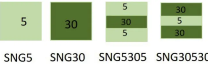
The two different reference (5 and 30 wt%) and two sandwich structures with 5-30-5 wt% MLG and 30-5-30 wt% MLG (Fig. 1) were produced.
The weight change of thefinal sintered composites was pre- cisely determined after sintering process. The density of all sintered composites was measured applying the Archimedes method.
2.2. Characterization techniques
Surface investigations of the sandwich composites were per- formed by a light-optical microscope (Keyence VHW-950F). The morphological properties of the layers were further studied by using scanning electron microscopy (SEM/FIB Carl Zeiss 1540XB) at 5 kV acceleration voltage. Everhart-Thornley and InLens secondary electron detectors and 36angle for sample tilting were used. A R€ontec Si(Li) detector and the Bruker Esprit 1.9 software were applied for EDX elemental analysis (acceleration voltage 8 kV).
Transmission electron microscopy (TEM, Carl Zeiss Libra 200 Cs, with accelerating voltage of 200 kV) observations were taken to study of the microstructure of the sintered composites. Elemental analysis (EDX) was performed on the samples using Oxford in- struments equipped on the TEM as well. The composites were mechanically grinded to obtain a relativeflat surface, and then were transferred to SEM for focused ion beam (FIB) milling. A typical lift- out process was used for sample preparation inside FIB/SEM tool (Zeiss Nvision 40). The carbon deposition and ion-beam Pt depo- sition as protections were performed on the sample surface before FIB milling.
Fig. 1.Schematic view of sintered composites with 5 and 30 wt% MLG and different sandwich structure. The numbers are showing the MLG content.
azsi et al. / Journal of Alloys and Compounds 832 (2020) 154984 2
Phase analysis was determined based on X-ray diffractograms recorded at room temperature using a Bruker AXS D8X-ray micro- diffractometer (XRD operating at 40 kV and 40 mA, Cu Karadiation, 0.15418 nm), equipped with a fucising G€obel mirror and a GADDS 2D detector. Diffraction patterns were collected for a 2qrange from 20to 90with 1/min steps usingflat plane geometry. The relative amount of phases in the composites was calculated using the Dif- frac. Eva software (Bruker). Microhardness (hardness testers LECO 700AT) was measured
By Vickers indenters at loads from 9.81 N to 150 N, the dwelling time was 10 s in all cases. The indentation fracture toughness was determined based on the Shetty equation [26]. The 3- and 4-point bending strength values for composites were determined by bending tests (tensile/loading machine INSTRON-1112). The di- mensions of the investigated specimens were 3 mm 4 mm50 mm. The surfaces of samples were thoroughly polished down to a surface roughness below 0.05mm. Scratch tests were conducted with the Bruker UMT-2 tool using a Vickers tip to deter- mine friction and wear behaviour of samples in dry sliding. The wear testing was carried out in air at room temperature. The applied loads were 1, 2.5 and 5 N, the scratch measurements lasted for 35s and 45 s.
3. Results and discussion
3.1. Macro- and microstructure of sandwich ceramics
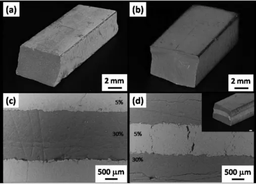
The reference and sandwich ceramics with various MLG content were realized by HIP sintering. Si3N4-ZrO2/5 wt% MLG (SNG5, Fig. 2a) and Si3N4-ZrO2/30 wt% MLG (SNG30,Fig. 2b) were prepared for understanding the effect of MLG content to structural and mechanical properties of composite (Fig. 2b). Novel laminated sandwich structure containing 5-30-5 wt% MLG in Si3N4-ZrO2 matrix (Figs. 2c) and 30-5-30 wt% MLG have been realized as well (Fig. 2d). The thickness of each ceramic layer in sandwich structure was changed between 1.0 and 1.6 mm (Fig. 2c and d).
Calculation of porosity values of different samples was made by the following equation:
4¼
r
realr
apparentr
realr
fluid*100;where
r
fluid¼0:997 g=cm3 (1)The porosity of sintered composites increased by almost two times when the MLG content increased from 5% to 30% (Table 1).
The density values were lower for samples with higher MLG con- tent owing to the porous microstructure of the samples induced by MLG particles.
Similar values were obtained in other research work [27]. The authors described that the graphene platelets induced porosity in the matrix and reduced the size of the Si3N4grains in the resulting composites.Duszaet al. [28] carried out statistical analyses of the grain sizes and revealed that in the case of monolithic Si3N4, the diameter of the matrix grains was around 0.4mm, while in the Si3N4/graphene composites the Si3N4grains had narrow size dis- tribution with maximum of 0.2mm. The monolithic silicon nitride was fully dense and the carbonfillers made densification of the composites more difficult. The pores were always associated with graphene platelets which leads to porosity increasing with increasing volume fraction of carbon phases.
Morphological investigations and elemental analysis of refer- ence composites are shown inFig. 3. In both casas, the spherioid ZrO2 particles and thin plate-like multilayer graphene platelets were incorporated into the mainly polygonal and rod-like Si3N4
particles.
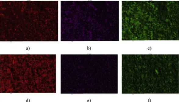
The size of Si3N4particles varies between 200 nm and 600 nm, while the average size of ZrO2particles 1e2mm. The 30 wt% MLG causes the higher porosity in structures (Fig. 3). This structural observation is in agreement with the numerical calculations from density measurements of sintered composites (Table 1). The elemental maps demonstrate that the MLG addition and other el- ements as Zr, O were homogeneously distributed during prepara- tion process (Fig. 4).
The elemental map distributions (Fig. 4a andd) confirmed the higher amount of carbon in the layer containing 30% MLG (Fig. 4d).
The zirconia content was also observed (Fig. 4b ande). The zirconia
Fig. 2.Light-optical images of the macrostructure of sintered Si3N4-ZrO2/MLG ceramics. a) single layer with 5% MLG, b) single layer with 30% MLG, c) sandvich structure with 5-30- 5 wt% MLG, and d) sandvich structure with 30-5-30 wt% MLG.
azsi et al. / Journal of Alloys and Compounds 832 (2020) 154984 3
particles were incorporated into the Si3N4 ceramics during the milling procedure, originating from the abrasion of ZrO2balls under controlled conditions. In the case of sandwich structure, the morphological observations of 5 wt%/30 wt% MLG border area clearly declared the differences (Fig. 5). The different kinds of particles were identified and marked with arrows in the SEM image.
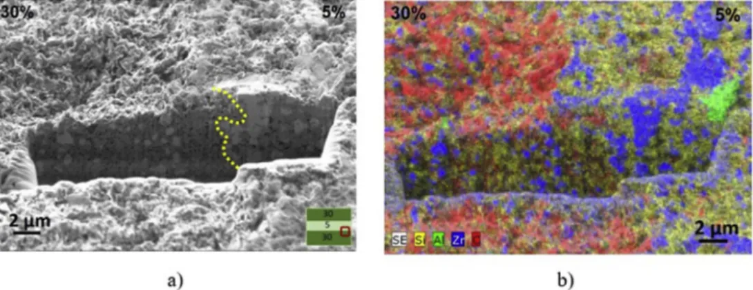
In order to get a deeper insight into the structure and compo- sition of prepared laminated composite samples, FIB cross-sections
were prepared to study the interface between two stacked layers containing different amount of MLG (Fig. 6). The SEM images show that the transition between the layers is continuous, and no cracks are visible. A slight agglomeration of ZrO2particles in the 5 wt%
MLG containing layer is visible.
The SEM image of the FIB cross-section also reveals that the sample contains many pores between the different particles due to the large difference in sizes and shapes of the grains.
Further structural investigations demonstrated the structure of Table 1
Density and porosity values of Si3N4-ZrO2/MLG composites with different structure and different MLG content.*calculated from average densities.
Fig. 3.SEM images of reference composites. a) 5 wt% MLG, b) 30 wt% MLG.
Fig. 4.Elemental composition analysis of Si3N4-ZrO2/MLG composite. a) 5 wt% MLG distribution (C), b) Zr distribution in composite with 5 wt% MLG, c) O distribution in composite with 5 wt% MLG, d) 30 wt% MLG, e) Zr distribution in composite with 30 wt% MLG, f) O distribution in composite with 30 wt% MLG.
azsi et al. / Journal of Alloys and Compounds 832 (2020) 154984 4
the sandwich structure (Fig. 7). It is visible that all layers in this case contain evenly distributed ZrO2 spheroid particles except at the interface of two layers. Important observation is that after sintering process Si3N4 and MLG only can be found in the interface area (without ZrO2phase).
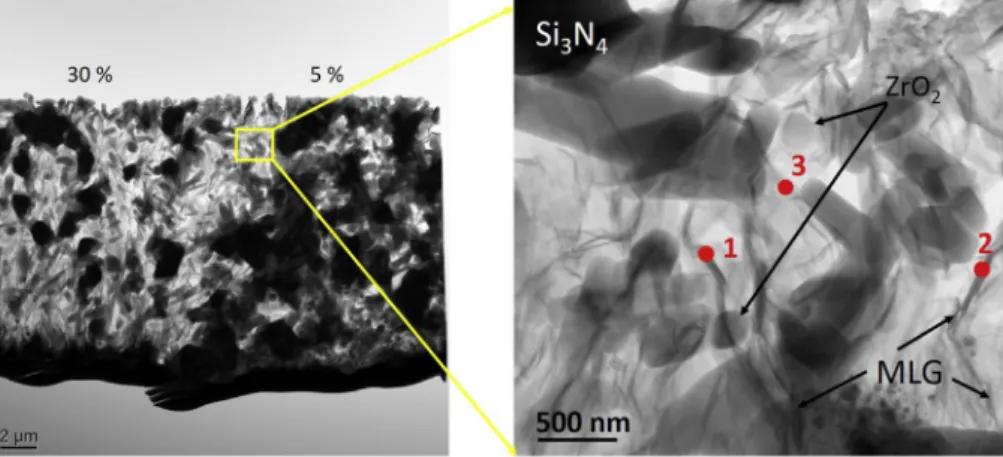
Detailed study of microstructure by TEM showed the distribution of MLG in the ceramic composite matrix (Fig. 8). The MLG addition distributed and embedded in Si3N4based matrix were clearly iden- tified in all part of sandwich structure after HIP sintering.
A large number of ZrO2 grains are located between the Si3N4
particles. The cross-section study revealed the presence of the multilayered graphene addition between the rod-like Si3N4parti- cles. The size of the MLG addition ranged between 100 nm and
600 nm, and their thickness ranges from 5 nm to 30 nm. The size of silicon nitride rods is about 300 nm in width and 800e1200 nm in length. Elemental analysis revealed 89 at%, 92 at% and 85 at% of carbon at spot 1, 2 and 3 respectively (Fig. 8). It indicates that the natural MLG particles were kept without sever oxidation during the whole manufacturing process. Elemental maps for major elements (Si, N, Zr, C and O) are shown inFig. 9. These investigations clearly identified the Si3N4, ZrO2 and MLG in both 5 wt% (Figs. 9a) and 30 wt% (Fig. 9b) composites. The oxygen concentration does not increase as a function of the carbon concentration, which indicates a low content of graphene oxide.
The phase composition of sintered composites was determined by XRD measurements.Fig. 10demonstrates the characteristic X- Fig. 5.Morphological study of 5 wt%/30 wt% MLG in the border area. a) SEM image of the interface, b) elemental map of carbon distribution in the SNG5305 composite.
Fig. 6.FIB cross section analysis of the 5 wt%/30 wt% interface of the composite SNG30530. a) SEM image, b) elemental map analysis of various elements (Si -yellow, Alegreen, Zre blue, Cered). (For interpretation of the references to colour in thisfigure legend, the reader is referred to the Web version of this article.)
Fig. 7.SEM images of the interfaces of Si3N4-ZrO2/30-5-30 wt% MLG sandwich composite (SNG30530).
azsi et al. / Journal of Alloys and Compounds 832 (2020) 154984 5
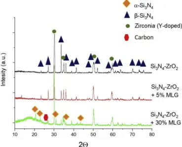
ray diffraction patterns of Si3N4-ZrO2matrix composites as well as of SNG5 and SNG30 composites, sintered at 1700C. In the case of base Si3N4-ZrO2 composite, only b-Si3N4 and Y-doped zirconia (from Y2O3additive) phases can be identified. This proves that the commercial a- Si3N4 powder transformed completely to b-Si3N4 during the hot isostatic pressing at 1700C, 20 MPa nitrogen gas pressure for 3 h dwelling time.
In the case of composite with 5 wt% MLG (SNG5), the phase transformation from a to b-Si3N4 was completed. The a-Si3N4
particles dissolved in the existing liquid phase and subsequently, newb-Si3N4nuclei were formed [29]. However, in the case of 30 wt
% MLG (SNG30), the phase transformation was partial; a-Si3N4
crystalline phase could be identified as well. This fact is in accor- dance with other published reports [30e32]. On the other hand, amorphous carbon phase was also detected at 2Qbetween 15 and 25 for composites with 30 wt% MLG. The ratios of identified ceramic phases in pure Si3N4-ZrO2composite were around 61%b- Si3N4, 39% Y doped ZrO2for Si3N4-ZrO2composite, 58%b-Si3N4, 42%
Fig. 8.STEM cross-section image of Si3N4-ZrO2/30-5-30 wt% MLG with detail of MLGs embedded in Si3N4based matrix and elemental analysis of three different places focusing to MLG.
Fig. 9.Elemental analysis of layers with different MLG content of Si3N4-ZrO2/30-5-30 wt% MLG sandwich structure. a) layer with 5 wt% MLG, b) layer with 30 wt% MLG.
azsi et al. / Journal of Alloys and Compounds 832 (2020) 154984 6
ZrO2were characteristic at composite with 5 wt% MLG (SNG5) and 51%a-Si3N416%b-Si3N4, 33% ZrO2identified the composite with 30 wt% MLG (SNG30).
3.2. Mechanical properties of Si3N4-ZrO2composites
The processing route and the microstructure have a decisive effect on thefinal mechanical properties of the composites. In the case of porous sandwich structure, the focus is not on the excellent mechanical properties. On the other hand, from the view of their potential applications their robustness is necessary. Thefinal me- chanical properties of Si3N4-ZrO2/MLG composites (hardness,
fracture toughness, 3- and 4-point bending strength) are summa- rized inTable 2.
A. Sayyadi-Shahrakiaet al. prepared the Si3N4/ZrO2composites by spark plasma sintering (SPS). Their evaluation of mechanical properties indicated that the hardness of the Si3N4-base compos- ites prepared declined from 16.6 to 13.2 GPa, whereas the fracture toughness improved from 5.8 to 7.1 MPa m1/2 by increasing ZrO2
content from 0 to 30 vol%, which were explained based on the in- situ formation of b-Si3N4 and the stress-induced phase trans- formation from tetragonal to monoclinic ZrO2, respectively [21]. In the case of hot pressed Si3N4/MLG with ~3 wt% ZrO2, the hardness of composites decreased from 17 to 13 GPa with increasing of MLG content from 0 wt% to 10 wt% [33]. Compared to Si3N4 based composites, the monolithic b-Si3N4 samples displayed a Vickers hardness of 16.3 ± 0.4 GPa, their 3-point bending strength was 549±23 MPa, while the fracture toughness was 6.9±0.25 MPa m1/
2[27].
The mechanical test of porous sandwich structures of hot isostatic pressed Si3N4-ZrO2/MLG composites showed compara- tively lower values (Table 2).
The hardness and fracture toughness (Table .2) decreased from
~6.51 GPa to 0.5 GPa with increasing of MLG addition from 5 wt% to 30 wt%, increasing of porosity of the final microstructure and content ofa- Si3N4.The same tendency was observed for bending strenght values (Table 2). The highest bending strength belonged to reference with 5 wt% MLG compared to 8 times lower value for reference with 30 wt% MLG. The sandwich structure 5-30-5 wt%
MLG enhanced the mechanical properties compared to reference ceramic with 30 wt% MLG. The position of the layer with higher graphene content, high ratio of a/b phase of Si3N4 and higher porosity have crucial effect on thefinal mechanical properties. The mechanical test confirmed that sandwich structure with 5-30-5 wt
% MLG showed 2 or 3 times better properties than sandwich structure with 30-5-30 wt% MLG. The main effect on mechanical properties had the layer with 30 wt% MLG and it regulated the mechanical behaviour offinal sandwich ceramic.
Fig. 10.X-ray diffraction patterns of the hot isostatic pressed Si3N4-ZrO2/MLG com- posites with 0 wt%, 5 wt% and 30 wt% MLG addition.
Table 2
Summarized mechanical properties of references and Si3N4-ZrO2/MLG composites.
azsi et al. / Journal of Alloys and Compounds 832 (2020) 154984 7
It is obvious that the MLG content caused considerable porosity, hence worsen the mechanical properties of composites, however, the carbon content makes the otherwise insulator ceramic conductor. On the other hand, the MLG content improve the elec- trical and thermal conductivity of composites [33,34] thereby they are very useful in various electronic applications. Moreover, the appropriately formed sandwich structure can enhance their me- chanical properties.
3.3. Tribological properties
A novel approach is the testing of scratch resistance of ceramic and understanding of their mechanisms of material failure. While hardness determination represents the result of a static indentation test, involving only a normal load applied to an indenter having different tip geometry (spherical, conical or pyramidal) and coming into contact with the surface of the material to be analysed, in the scratch test the normal load is applied to an indenter with the same geometry, but into contact with the surface of a moving sample. The effects induced on the surface of the sample by the combination of
the normal and tangential loads, overcoming, under definite con- ditions, the strength of the material, lead to an elastic-plastic deformation the effect of which is the formation of a scar [34].
The friction coefficient was resulted between 0.35 and 0.7, respectively (Fig. 11). The measurements clearly gave two typical values for layer with 5 wt% MLG and 30 wt% MLG. These values are characteristic not only for reference, but may be observed for both sandwich structures (5-30-5 wt% and 30-5-30 wt%). Applying the aqueous environment, the Si3N4/MLG composites sintered by hot pressing showed the friction coefficient between 0.1 and 0.225.
These low values were related to the graphene containing tribo- films, non-porous structure and characteristic b-Si3N4 ceramic matrix [33]. The increasing applied load from 1 N to 5 N caused higher values of friction coefficient from 0.35 to 0.5 for Si3N4-ZrO2/ 5 wt% MLG reference (Fig. 11a). The tribological properties in reference with 30 wt% MLG are characterized by friction coefficient 0.65 undependent of applied load (Fig. 11b). The lower porosity, presence of mainlyb-Si3N4phase in matrix assured lower friction coefficient, whereas the higher MLG could not have beneficial role in the frictional characteristics. Both sandwich structures reflected Fig. 11.Friction coefficient (COF) measured by scratch tests. a) reference with 5 wt% MLG, b) reference with 30 wt% MLG, c) Si3N4-ZrO2/5-30-5 wt% MLG, d) Si3N4-ZrO2/30-5-30 wt%
MLG.
azsi et al. / Journal of Alloys and Compounds 832 (2020) 154984 8
the inherent character of references (Fig. 11c and d). For porous sandwich structures no tribofilm formation was observed.
4. Conclusions
In summary, MLG added porous Si3N4-ZrO2 composites were prepared by applying HIP. The samples were sintered by stacking alternative layers of the ceramics with different (5 or 30 wt%) MLG content. The SEM images and the corresponding elemental maps revealed that the spheroid ZrO2particles and the thin, plate-like MLG particles were evenly incorporated into the mainly polyg- onal and rod-like Si3N4 particles. The size of the Si3N4 particles changed between 200 nm and 600 nm, while the average size of ZrO2particles was 1e2mm. According to the XRD measurements, the phase transition froma-Si3N4tob-Si3N4phase was complete for all samples, except for the sample containing 30 wt% MLG. The porosity of the samples increased by around two times with increasing of the MLG content. The density values were lower for samples with high MLG content owing to their very porous microstructure. The mechanical test confirmed that sandwich structure with combination of 5-30-5 wt% MLG layers showed 2 or 3 times better properties than structure with 30-5-30 wt% MLG.
The main effect on mechanical properties had the layer with 30 wt%
MLG with porosity of ~66% and higha/b-Si3N4 ratio of sintered ceramic matrix. Testing of the sandwich structures by scratch measurements in dry conditions reflected the inherent character of references, thus the layer with 5 wt% MLG resulted friction coeffi- cient ~0.5 and layer with 30 wt% MLG ~0.7. No tribofilm formation was observed.
Declaration of competing interest
The authors declare that they have no known competing financial interests or personal relationships that could have appeared to influence the work reported in this paper.
CRediT authorship contribution statement
K. Balazsi: Methodology, Writing - original draft. M. Furko:
Formal analysis, Investigation.Z. Liao:Investigation, Validation.J.
Gluch:Resources.D. Medved:Investigation.R. Sedlak:Investiga- tion, Validation. J. Dusza: Resources, Funding acquisition. E.
Zschech:Resources, Funding acquisition.C. Balazsi:Conceptuali- zation, Supervision, Project administration, Funding acquisition, Writing - review&editing.
Acknowledgements
The authors acknowledge the support given by the Hungarian National Research Development and Innovation Office for the funding NKFIH NN 127723, NKFIH-NNE 129976 and FLAG-ERA
“Multifunctional Ceramic/Graphene Coatings for New Emerging Applications”. Funding from DFG (project number 397380564) is gratefully acknowledged. Thanks to Mr. V. Varga, Mr. T. Zagyva, and Dr. Z.E. Horvath (MTA-EK) for sample preparation, optical micro- scopy and XRD measurements. Thanks to Mrs. Y. Standke (Fraunhofer IKTS Dresden) for FIB sample preparation and SEM imaging.
References
[1] F.L. Riley, Silicon nitride and related materials, J. Am. Ceram. Soc. 83 (2000) 245e265,https://doi.org/10.1111/j.1151-2916.2000.tb01182.x.
[2] Y.F. Xia, Y.P. Zeng, D.L. Jiang, Microstructure and mechanical properties of porous Si3N4 ceramics prepared by freeze-casting, Mater. Des. 33 (2012) 98e103,https://doi.org/10.1016/j.matdes.2011.06.023.
[3] C.R. Zou, C.R. Zhang, B. Li, Microstructure and properties of porous silicon nitride ceramics prepared by gel-casting and gas pressure sintering, Mater.
Des. 44 (2013) 114e118,https://doi.org/10.1016/j.matdes.2012.07.056.
[4] Y. Inagaki, N. Kondob, T. Ohji, High performance porous silicon nitrides, J. Eur.
Ceram. Soc. 22 (2002) 2489e2494,https://doi.org/10.1016/S0955-2219(02) 00107-3.
[5] Y.F. Xia, Y.P. Zeng, D.L. Jiang, Dielectric and mechanical properties of porous Si3N4ceramics prepared via low temperature sintering, Ceram. Int. 35 (2009) 1699e1703,https://doi.org/10.1016/j.ceramint.2008.09.010.
[6] J.F. Yang, Z.Y. Deng, T. Ohji, Fabrication and characterisation of porous silicon nitride ceramics using Yb2O3as sintering additive, J. Eur. Ceram. Soc. 23 (2003) 371e378,https://doi.org/10.1016/S0955-2219(02)00175-9.
[7] C. Balazsi, Z. Shen, Z. Konya, Z. Kasztovszky, F. Weber, Z. Vertesy, L.P. Biro, I. Kiricsi, P. Arato, Processing of carbon nanotube reinforced silicon nitride composites by spark plasma sintering, Compos. Sci. Technol. 65 (2005) 727e733,https://doi.org/10.1016/j.compscitech.2004.10.006.
[8] C. Ramírez, S.M. Vega-Diaz, A. Morelos-Gomez, F.M. Figueiredo, M. Terrones, M.I. Osendi, M. Belmonte, P. Miranzo, Synthesis of conducting graphene/Si3N4 composites by spark plasma sintering, Carbon 57 (2013) 425e432,https://
doi.org/10.1016/j.carbon.2013.02.015.
[9] C. Balazsi, Z. Konya, F. Weber, L.P. Biro, P. Arato, Preparation and character- ization of carbon nanotube reinforced silicon nitride composites, Mater. Sci.
Eng. C 23 (6e8) (2003) 1133e1137, https://doi.org/10.1016/
j.msec.2003.09.085.
[10] K. Balazsi, M. Furko, Zs Fogarassy, C. Balazsi, Examination of milled h-BN addition on sintered Si3N4/h-BN ceramic composites, Process. Appl. Ceram. 12 (4) (2018) 357e365,https://doi.org/10.2298/PAC1804357B.
[11] C. Balazsi, Silicon nitride composites with different nanocarbon additives, J. Kor. Ceram. Soc. 49 (4) (2012) 352e362, https://doi.org/10.4191/
kcers.2012.49.4.352.
[12] C. Lee, X.D. Wei, J.W. Kysar, J. Hone, Measurement of the elastic properties and intrinsic strength of monolayer graphene, Science 321 (2008) 385e388, https://doi.org/10.1126/science.1157996.
[13] J.T. Paci, T. Belytschko, G.C. Schatz, Computational studies of the structure, behavior upon heating, and mechanical properties of graphite oxide, J. Phys.
Chem. C 111 (2007) 18099e18111,https://doi.org/10.1021/jp075799g.
[14] M.J. McAllister, J.L. Li, D.H. Adamson, H.C. Schniepp, A.A. Abdala, J. Liu, M. Herrera-Alonso, D.L. Milius, R. Car, R.K. Prudhomme, I.A. Aksay, Single sheet functionalized graphene by oxidation and thermal expansion of graphite, Chem. Mater. 19 (2007) 4396e4404, https://doi.org/10.1021/
cm0630800.
[15] J.H. Warner, F. Schaffel, A. Bachmatiuk, M.H. Rummeli, Graphene: Funda- mentals and Emergent Applications, Elsevier, Oxford, 2013. ISBN-13: 978- 0123945938.
[16] P. Rutkowski, L. Stobierski, G. Gorny, Thermal stability and conductivity of hot-pressed Si3N4-graphene composites, J. Therm. Anal. Calorim. 116 (2014) 321e328,https://doi.org/10.1007/s10973-013-3565-6.
[17] H. Porwal, S. Grasso, M.J. Reece, Review of grapheneeceramic matrix com- posites, Adv. Appl. Ceram. 112 (2013) 443e454, https://doi.org/10.1179/
174367613X13764308970581.
[18] Y. Yang, B. Li, C. Zhang, S. Wang, K. Liu, B. Yang, Fabrication and properties of graphene reinforced silicon nitride composite materials, Mater. Sci. Eng. A644 (2015) 90e95,https://doi.org/10.1016/j.msea.2015.07.062.
[19] J. Llorente, C. Ramirez, M. Belmonte, High graphene fillers content for improving the tribological performance of silicon nitride-based ceramics, Wear 430e431 (2019) 183e190,https://doi.org/10.1016/j.wear.2019.05.004.
[20] P. Miranzo, M. Belmonte, M. Isabel Osendi, From bulk to cellular structures: a review on ceramic/graphenefiller composites, J. Eur. Ceram. Soc. 37 (2017) 3649e3672,https://doi.org/10.1016/j.jeurceramsoc.2018.08.001.
[21] A. Sayyadi-Shahraki, S.M. Rafiaei, S. Ghadami, K.A. Nekouee, Densification and mechanical properties of spark plasma sintered Si3N4/ZrO2nano-composites, J. Alloys Compd. 776 (2019) 798e806, https://doi.org/10.1016/
j.jallcom.2018.10.243.
[22] L. Cheng, M. Sun, F. Ye, Y. Bai, M. Li, S. Fan, L. Zhang, Structure design, fabri- cation, properties of laminated ceramics: a review, Int. J. Light. Mater. Manuf.
1 (2018) 126e141,https://doi.org/10.1016/j.ijlmm.2018.08.002.
[23] M. Sun, Y. Bai, M. Li, S. Fan, L. Cheng, Structural design and energy absorption mechanism of laminated SiC/BN ceramics, J. Eur. Ceram. Soc. 38 (2018) 3742e3751,https://doi.org/10.1016/j.jeurceramsoc.2018.04.052.
[24] A.J. Medesi, F. Hagedorn, M. Schepperle, C. Megnin, T. Hanemann, The co- casting process: a new manufacturing process for ceramic multilayer de- vices, Sensors Actuators A Phys. 251 (2016) 266e275,https://doi.org/10.1016/
j.sna.2016.07.033.
[25] P. Kun, F. Weber, C. Balazsi, Preparation and examination of multilayer gra- phene nanosheets by exfoliation of graphite in high efficient attritor mill, Cent. Eur. J. Chem. 9 (1) (2011) 47e51,https://doi.org/10.2478/s11532-010- 0137-5.
[26] D.K. Shetty, I.G. Wright, P.N. Mincer, A.H. Clauer, Indentation fracture of WCeCo cermets, J. Mater. Sci. 20 (1985) 1873e1882,https://doi.org/10.1007/
bf00555296.
[27] J. Balko, P. Hvizdos, J. Dusza, C. Balazsi, J. Gamcova, Wear damage of Si3N4- graphene nanocomposites at room andelevated temperatures, J. Eur. Ceram.
Soc. 34 (2014) 3309e3317, https://doi.org/10.1016/
j.jeurceramsoc.2014.02.025.
[28] J. Dusza, J. Morgiel, A. Duszova, L. Kvetkova, M. Nosko, P. Kun, C. Balazsi,
azsi et al. / Journal of Alloys and Compounds 832 (2020) 154984 9
Microstructure and fracture toughness of Si3N4þgraphene platelet compos- ites, J. Eur. Ceram. Soc. 32 (2012) 3389e3397, https://doi.org/10.1016/
j.jeurceramsoc.2012.04.022.
[29] G.-H. Peng, X.-G. Li, M. Liang, Z.-H. Liang, Q. Liu, W.-l. Li, Spark plasma sintered high hardness a/b Si3N4composites with MgSiN2as additives, Scripta Mater.
61 (2009) 347e350,https://doi.org/10.1111/j.1551-2916.2009.03139.x.
[30] X.J. Liu, Z.Y. Huang, Q.M. Ge, Microstructure and mechanical properties of silicon nitride ceramics prepared by pressureless sintering with MgO- eAl2O3eSiO2 as sintering additive, J. Eur. Ceram. Soc. 25 (14) (2005) 3353e3359,https://doi.org/10.1016/j.jeurceramsoc.2004.08.025.
[31] B.T. Lee, H.D. Kim, Effect of sintering additives on the nitridation behavior of reaction-bonded silicon nitride, Mater. Sci. Eng. A364 (2004) 126e131,
https://doi.org/10.1016/j.msea.2003.07.005.
[32] E.M.M. Ewais, M.A.A. Attia, A. Abousree-Hegazy, R.K. Bordia, Investigation of the effect of ZrO2and ZrO2/Al2O3additions on the hot-pressing and properties of equimolecular mixtures of a- and b-Si3N4, Ceram. Int. 36 (2010) 1327e1338,https://doi.org/10.1016/j.ceramint.2010.01.018.
[33] C. Balazsi, Zs Fogarassy, O. Tapaszto, A. Kailer, C. Schr€oder, M. Parchoviansky, D. Galusek, J. Dusza, K. Balazsi, Si3N4/graphene nanocomposites for tribolog- ical application in aqueous environments prepared by attritor milling and hot pressing, J. Eur. Ceram. Soc. 37 (12) (2017) 3797e3804, https://doi.org/
10.1016/j.jeurceramsoc.2017.03.022.
[34] A. Tucci, J.-B. Guion, L. Esposito, Microstructure and scratch resistance of ceramic surfaces, J. Sci. (2008) 229e237.
azsi et al. / Journal of Alloys and Compounds 832 (2020) 154984 10