Design of Tactile Measuring Probes for Coordinate Measuring Machines
Gyula Hermann
Budapest Tech, Hungary hermann.gyula@nik.bmf.hu
Csongor Sántha
BrainWare Ltd, Budapest, Hungary brainware@t-online.hu
Abstract: With the appearance of micromachined mechanical elements and nanotechnology, increased demand can be observed for coordinate measuring systems having submicron accuracy. Probes are major components of such a coordinate measuring machine. They contribute to a large extend to measurement uncertainty of the CMM. In this paper a new low cost design is presented. The moving element of the probe head consists of the stylus and a cross form intermediate body with a small aluminum enhanced mirror at each ends and at the center. The intermediate body is suspended on four springs made of beryllium-copper foils. The displacement of the probe tip is calculated from the displacement and the rotations of the mirrors measured by modified optical pick-ups.
1 Introduction
Measurement uncertainty below 0,1 μm is called for in 3D coordinate measurement for the applications introduced by the apperiance of micromechanical elements [5], [7], [10]. It was recognized that the uncertainty is mainly determined by the accuracy of the sensing probe, thermal drift of the probing point and the metrological frame. The development of probes with a measuring uncertainty far below 0,1 μm will be an important contribution to the above mentioned goal [11].
2 Design Considerations
The probe performance is affected by a number of factors, which have to be taken into account in the design process. The errors can be classified into the following categories [2]:
Geometric errors: These errors are inherent to the manufacturing and assembly processes. Due to the limited accuracy of manufacturing processes, the probe can show inaccuracies. Typical example of the limited manufacturing accuracy is the deviation from the sphericity of the probe tip. Typical assembly error is the misalignment of the transducers.
Figure 1
Measurement error due to sphericity error
Finite stiffness: The probing force causes a bending of the stylus according to equation (1):
4 3
. 3
. 64
Ed w
sFl
= π
(1)
Where
► ws is the amount of bending
► F is the probing force
► E is Young’s modulus of the styli material
► l is the styli length, and
► d is the styli diameter assumed to be cylindrical
The resulting deflections of the considered stylus geometry and materials are given in Table 1.
Table 1
Probe tip deflection as a result of the sensing force Probing
force (mN) 1,00E-01
Material Diameter (mm) Length (mm) Deflection (nm)
Steel 1,00E+00 1,50E+01 1,11E+01
Tungsten 1,00E+00 1,50E+01 5,73E+00
Probing force also causes elastic deformation of the surface sensed and the tip ball due to Hertzian stress. The extent of the deformation depends on the materials, micro- and macrogeometric forms and the force. In case of touching two spheres the flattening in the contact area is given by formula (2).
3 2
2 2
) 1 .(
25 , 2
r E w
t= − ν F
(2) Where wt is the maximum flattening in the contact area
► F is the probing force
► ν is the material’s Poisson’s ratio
► E is Young’s modulus and
► r is the effective contact area radius (1/r=1/r1+1/r2)
For a ruby tip sphere of 3 mm diameter the touching a steel plane with a probing force of 0,1 mN, the flattening is about 1,3 nm.
Figure 2
Errors caused by the sensing force
Static probing results in over-travel, which is at a measuring speed of 1mm/s approximately 7 µm. The resulting force between the workpiece and the probe tip can be calculated as the product of the over-travel Δx0 and the stiffness of the suspension cprobe. To avoid plastic deformation the subsequent inequality should hold:
2 2 3 0 3 probe
. c 6
E r xo
π
p tip≤ Δ
(3) It is clear that in case of a small probe tip the measuring speed and the stiffness of
the suspension should be decreased.
Thermal errors: Internal and environmental influences can introduce thermal distortion, which in turn, effect the probe accuracy. Zero drift is a typical example of such an error. Also the location of the stylus tip can seriously change due to thermal expansion of the stylus. Deflection resulting from thermal destortion can be avoided by designing thermally isotropic (symmetric) structures.
Transducer errors: Due to their size and resolution piezo-resistive strain gauges, capacitors and various types of inductive transducers [14] are used as measuring element in probing systems.
Displacement of the probe tip can be determined by measuring the deformation of the probe suspension using strain gauges. They convert the elongation into a proportional electric signal. Usually strain gauges are glued to the stressed surface, that may lead to hysteresis and creep, which results in uncertainty. However by using evaporation, lithography and etching, familiar techniques in integrated circuit fabrication the strain gauges can be integrated into the suspension of the probe. Piezo-resistive strain gauge shows sensitivity to temperature variation.
When using a capacitance sensor [5], the sensor surface is the electrified plate and the measuring target is the other plate. The sensor electronics continually change the voltage on the sensor surface and the current required to make the change is measured by the circuit and indicates the capacitance between the probe and the target. The capacitance between the plates is determined by the size of the plates, gap size and the material between the plates. In capacitance sensing the size of the sensor and the target and the dielectric material (usually air) remains constant, only the gap size varies.
C Gap 1
≈
(4) From equation (4) follows that the capacitance is a hyperbolic function of the gap,
thus exhibiting non-linearity. However in the working range the non-linearity error is less than 1%. If the sensor surface or the target is tilted, the shape of the spot where the field hits the target elongate and because of different behaviour of the electric field, measurement errors will be introduced. A more troublesome problem is when the target or the transducer exhibit expansion or contraction due to the variation of the temperature. The dielectric constant of the air is effected by humidity and this may introduce an error of 0,5% assuming a humidity change from 50 to 80% RH.
Transducers based on the inductive principle are widely used for displacement measurement. A soft magnetic material core is moved inside a coil changing the inductance, which a measure of the position of the core. In order to compensate for the hyperbolic characteristic two coils are used in a differential setup called differential transformer. The response characteristic shows an inflection point and the system is used in the vicinity of this inflection point. The device forms an excellent 1D probe.
An alternative is to use scanning probe microscopy combined with high precision short range motion control in order to increase resolution and at the same time maintain the measuring range.
Hysteresis. These are residual errors that occur when the load on a loop of structural components is increased and decreased in a cyclic way. Hysteresis is caused by friction between the components and by internal material properties.
Because the force due to measurement is not of cyclic nature hysteresis errors can not be predicted, so they should be avoided. Using flexures is advantages because the exibit neglectible hysteresis.
3 Overview of the Mechanical Construcions
In the last year a number of various probe constructions has been built in order to investigate their properties under different circumstances. The probe similar to the one developed at the NPL is based on capacitive sensors as measuring elements.
The flexture structure is made from tungsten carbide tubing and beryllium-copper strips as given in Figure 2. This construction is stiff and light. The moving part weights only 500 mg. The suspension is isotropic and its stiffness is 10 N/m [8], [9].
Figure 3 The tripod probe
The probe has a measuring range of about 50 µm limited by the gap of the capacitive sensors and the 3D uncertainty is 40 nm. The probe was designed to operate with a standard probing force of 0,1 mN, corresponding to a pin deflection of 10 µm. The resolution of the probe is determined by the resolution of the capacitive gauges, which is 3 nm.
The correspondence between the tip displacement and the measurement values is given by the matrix equation (5).
(5)
The relationship between the tip displacement and the sensing force is given by equation (6).
__
__
0 0
0 0
0 0
X c c c F
z xy xy
⎟⎟
⎟
⎠
⎞
⎜⎜
⎜
⎝
⎛
=
(6)
Where
⎟⎟
⎠
⎞
⎜⎜
⎝
⎛ ⎟⎟− + + +
⎠
⎞
⎜⎜
⎝
⎛
⎟⎟⎠
⎜⎜ ⎞
⎝
⎛ − + −
= 3
1 12
1 1 21 , 3 0 1 ) 1 ( 2
1 2
3
2 2 2
2 4
4 2
3
s s s
s s
s s
s s
s s
st s
xy l
x l y l y w
t w
t l
l c Ewt
ν
(7) and
3 3
3
s
z
l
c = Ewt
(8)
where
► E is Young’s modulus of the spring material
► w stands for width of the spring
► t is the thickness of the spring
► ls is it’s length
► lst is the length of the stylus
tip
st s st
s
st s st
s st s
X
l r l
r
l r l
r l
r
M
⎟⎟
⎟⎟
⎟⎟
⎟
⎠
⎞
⎜⎜
⎜⎜
⎜⎜
⎜
⎝
⎛
−
−
−
=
1 2 3
1 2
1
1 2 3
1 2 1
1 0
The disadvantages of this construction are that due to parasitic translations of the rods when they are translated out of the xy-plane, the probe will rotate around the z-axis when moved in vertical direction. Additionally, when probe tip is not exactly on the z-axis, it will move over a small predictable distance in x- or y- direction when moved in the vertical direction.
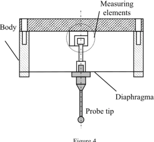
In an other construction the stylus is suspended by a thin diaphragm flexure. The stylus is extended with a tungstan carbid tube inside the body ending in a polished accurate cube. The x, y and z components of the displacement of this cube are measured using non-contact sensors and from these values the displacement of the probe tip is calculated.
Figure 4 The diaphragm probe
The symmetric diaphragm flexure comprises of multiple folded-beam pairs. The rotational symmetry eliminates the parasitic rotation of the diaphragm, and the folded-beam geometry relieves any axial stress associated with with out-of-plane motions. The increased effective length of the folded-beams provides larger range of motion along the degrees of freedom. However this structure reduces the rotational stiffness along the z-axis.
Probe tip Body
Diaphragma Measuring
elements
Figure 5
The geometry of the symmetric diaphragm flexure
In Fig. 5 the deformation of the flexure is given as a result of the probe tip deflection. The associated probe tip displacement is about 100 nm.
Figure 6
Result of the FEM analysis of the flexure
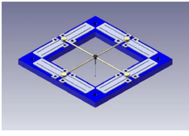
The mechanical construction of the quadropod probe (Fig. 6) consists of a rectangular frame made of Invar, a metal with low thermal expansion. The stylus is mounted at the centre off a stiff cross-form intermediate body made of tungsten- carbide tubes. The intermediate body is suspended on four slender rods, made from 50 μm thick beryllium-copper foil.
Figure 7 The mechanical construction
The symmetrical arrangement of the design is intended to limit the number of degrees of freedom of the stylus structure. The suspension prevents the translational motion of the stylus along the x- and y-axis directions, and inhibits rotational motion about the z-axis [2].
Figure 8 The result of FEM analysis
To measure the displacement of the mirror at the center of the intermediate body and the rotations at the ends of the tungsten carbide bars commercially available pick-up units are used.
The working principle is described in the following paragraph. A laser beam emitted from a laser diode passes through a polarized beam splitter, collimated and then focused onto an object surface by the objective lens. The reflected beam passes back through the objective lens and a cylindrical lens or a tilted glass plate.
The cylindrical lens or the tilted glass plate acts as a beam-shaping element.
Finally the beam falls on a four quadrant photodiode, with a current amplifier for each element.
Figure 9
Configuration of the pick-up head
If the object surface is perfectly in focus, the laser beam on the photosensor is circular. When the object surface is out of focus, the spot on the four quadrant photosensors appears more elongated. The shape change can be detected using simple arithmetic; (VA+VC)-(VB+VD) where VA- VD are the preamplifier output voltages of the photosensors. The focus error signal vs. Vertical surface distance shows an S-curve, with a linear region of ~6μm.
Figure 10
Laser spot shape and the S-curve D
B A C
D B A C
D B A C
Defocus
Linear region
Polarizing beam splitter
¼ wave plate
Collimator Four quadrant detector
Cylindrical lens
Measured object Aspherical lens and
voice coil D
B A C
Measuring the focus error signal the voice coil motor can drive the objective lens into a position at which the focal point returned to the surface of the measured object. In such a way the displacement of the mirrors at the end of the tungsten carbide tubing can be measured with nanometer resolution.
The magnitude of these signals can be used to determine the z coordinate of the probe tip.
To measure the rotation, an angular sensor based on the electronic autocollimator principle was applied. In order to keep the costs low again an optical pick-up from CD drive was used. A change in the angle of the mirror at the end of the tungsten carbide bar causes a corresponding shift in the position of the focused laser beam on the surface of the four quadrant photodiode.
Figure 11
The working principle of the angle sensor
The signals coming from the photodiodes are evaluated as follows:
x-direction: Vx = (VA+VB )- (VC+VD) y-direction: Vy = (VD+VA) - (VC+VB)
From these signals the angular change, the x and y coordinates of the probe tip deflection, can be derived.
4 Measuring Uncertainty
The measuring uncertainty of the probe is mainly determined by the resolution of the optical pick-ups, which according to literature data is the order of a few nanometers.
It was assumed that the tungsten carbide tubing and the stylus form a rigid body.
However this is not case in practice. As the probe stylus is an elastic body, its deformation must also be taken into account when calculating the displacement.
Laserdiode Four quadrant
photodiode
Measuring mirror Collimating
Semitransparent lens mirror
The stylus can be considered as a cantilever beam. Assuming that the deformation in the z-axis direction can be neglected, and the deformation in the x-y plane can be computed in the possession of the material constants exact knowledge.
As the probe body is made out of Invar, a very low thermal expansion material and the construction was kept symmetrical from the thermal point of view, temperature variation can influence the measurement accuracy if the material of the interchangeable stylus differs from that of the intermediate body.
At a number of places in the thermal loop parts were glued together because there was not alternative. However glue layers can introduce unwanted effects, like hysteresis or creep. To minimize these effects a thin layer was used. As very small forces act on the tip and the required time span for stability is limited problems of this nature are not expected.
5 Calibration System
The measuring capabilities of the probe were determined using the experimental set-up given in Fig. 6. The tip of the probe was displaced using a three-axis Nanopositioner. The displacement values of the nanopositioner were in turn measured by a short distance plane mirror interferometer. The signals generated by the translation and the 2D rotation were processed by a signal processing circuit and the collected and converted into digital form by a data acquisition card.
The calibration system consists of a commercially available nanopositioning table with 100 x 100 x 100 μm working space assembled on a base plate. The displacements along the coordinate systems axis of the nanopositioning table are measured by three dual-beam laser interferometers. Hereby also the angular error of the motion is captured simultaneously.
All critical mechanical parts of the system are constructed of an alloy with a low coefficient of thermal expansion (Invar).
Figure 12
Calibration set-up for determining the measuring capabilities
To ensure the perpendicularity of the probe to be calibrated and the x-y surface of the Nanopositioning stage an alignment mechanism was developed. It consists of a flexure stage powered by two manual micrometers and on top of it, there is a precision rotational stage. A third micrometer is available for the adjustment in the z direction.
The components and resulting uncertainty of the calibration system are given in the following table.
Table 2
Uncertainty components of the calibration system Source of
uncertainty
Probability
distribution Divis or
Standard uncertainty Error due to finite
resolution Rectangular √3 0,57 nm Wavelength
compensation Rectangular √3 0,025 nm Dead-path
correction
Rectangular √3 12,4 nm Cosine error Rectangular √3 0,02 nm Combined
standard uncertainty
Normal - 12,4 nm
SIOS Interferometer
Precision stage
Nanopositioner PI-762.3
Advantech PCI-1714UL
DAQ-Card Focus error
signal
6 Measuring Results
The set-up enables the calibration of probes to 20 nm uncertainty with 1 nm resolution. In Fig. 8 the calibration result of the quadropod with optical sensors.
The approach direction was along the x axis. Similar results were gained for the other directions as well. The experiment presented here was carried out on a granite table on vibration damping foots, at a room temperature 20ºC and relative humidity of 60%. Extensive tests are prepared for the tripod and the other probe constructions as well.
Residual
0 10 20 30 40 50 60
0 0,3 0,6 0,9 1,2 1,5 1,8 2,1 2,4 2,7 3 3,3 3,6 3,9 4,2 4,5 4,8
Displacement (μm)
Residual (nm)
Figure 13
Difference between displacement as measured by interferometer and displacement calculated from optical sensor’s output
Conclusions
With the increasing application of micromechanical elements co-ordinate metrology faces a new challenge. One major problem to be solved is the design and construction of adequate probes for sensing these tiny and accurate objects.
The paper presents various possible construction for high precision probes. These probes can be manufactured using conventional technologies and there resolution can be increased by using new sensory technologies and applying advanced control systems.
Acknowledgment
The author gratefully acknowledge the support provided to this project by the National Science Foundation (OTKA) under the contract no. T 048850.
References
[1] S. Awtar “Synthesis and Analysis of Parallel Kinematic XY Flexure Mechanisms” PhD. Thesis, MIT, 2003
[2] S. Cao, U. Brand, T. Kleine-Besten, W. Hoffmann, H. Schwenke, S.
Bütefisch, S. Büttgenbach “Recent Development in Dimensional Metrology for Microsystem Components” Microsystem Technologies 8 (2002) 3-6 Springer-Verlag 2002
[3] H. Haitjema, W. O. Pril, P. H. J. Schellekens “A Silicon-etched Probe for 3- D Coordinate Measurements with an Uncertainty Below 0.1 μm” IEEE Transactions on Instrumentation and Measurement, Vol. 50, No. 6, (2001) pp. 1519-1523
[4] A. Küng, F. Meli, R. Thalmann: Ultraprecision Micro-CMM Using a Low Force 3D Touch Probe” Measurement Science and Technology 18 (2007) pp. 319-327
[5] F. Meli, M. Fracheboud, S. Bottinelli, M. Bieri, R. Thalmann, J-M.
Breguet, R. Clavel “High Precisision, Low Force 3D Touch Probe for Measurements on Small Objects” euspen Int. Topical Conference, Aachen, Germany, May 2003
[6] W. O. Pril „Development of High Precision Mechanical Probes for Coordinate Measuring Machines” PhD. Thesis TU Eindhoven 2002
[7] Shih-Chi Chen, D. Golda, A. Hermann, A. H. Slocum “Design of an Ultra Precision Diaphragm Flexure Stage for Out-of-Plane Motion Guidance”
Proc. DETC’04 ASME 2004 Design Engineering Technical Conf. Sept. 28- Oct. 2, 2004, Salt Lake City, Utah, USA
[8] A. Sohn, T. A. Dow, E. A. Marino “A New Design for a Three- Dimensional Measuring Probe”
[9] W. P. van Vliet, P. H. J. Schellekens “Accuracy Limitations of Fast Mechanical Probing” Annals of the CIRP 45(1) 483-487
[10] W. P. van Vliet, P. H. J. Schellekens “Development of a Fast Mechanical Probe for Coordinate Measuring Machines” Precision Engineering Vol. 22 (1998) pp. 141-152
[11] A. Weckenmann, T. Estler, G. Peggs, D. McMurtry “Probing Systems in Dimensional Metrology” Annals of the CIRP
[12] A. Weckenmann, G. Peggs, J. Hoffmann “Probing Systems for Dimensional Micro- and Nano-Metrology” Measurement Science and Technology 17 (2006) pp. 504-509