The Influence of Machine-Part Measuring
Strategies for Coordinate Measuring Devices on the Precision of the Measured Values
Jana Moravčíková, Peter Pokorný
Slovak University of Technology in Bratislava, Faculty of Materials Science and Technology in Trnava, J. Bottu 25, 917 24 Trnava, Slovak Republic
jana.moravcikova@stuba.sk, peter.pokorny@stuba.sk
Abstract: This article describes various strategies of measurement and their influence on the accuracy of measured parameters. Maintaining and, in particular, increasing the accuracy of production plays a key role in production companies. Coordinates-based measuring technology enables measuring parameters with a high degree of accuracy, depending on the measuring method used and specific conditions. The scanning system available to the CMM has a significant impact on the result of the measuring. The measuring experiment is executed on a calibration ring of a known size using the PRISMO Ultra coordinate-measuring machine. The goal of the experiment is an analysis of the effect of measuring strategies while measuring a machine-part on the values of roundness and diameter of the calibration ring. This includes a change of measuring method, scanning rate, diameter of the scanning stylus, as well as the evaluation filter. The RONDCOM 60A high-precision measuring device is designed to establish reference values of roundness for the proposed experiment measurement. This paper focuses on the analysis of the impact of conditions of measuring roundness and diameter of the calibration ring on the results of the measurements.
Keywords: coordinate measuring; measurement strategy; accuracy; roundness; diameter
1 Introduction
Production technologies, as well as measuring methods, are currently showing a trend towards increased accuracy. The required geometric and dimensional accuracy of a produced machine-part depends to a large degree on the accuracy of the machine tools and their abilities. It was a subject of the study [1, 2, 3, 4]. The precision of the produced part also determines the conditions of its assemblage and, therefore, the outcome of the assembly process. Along with increased accuracy practical requirements also arose for controlling highly precise dimensions. Coordinate measuring machines (CMM) are often currently used to
cover this need [5]. These machines are highly precise with a low degree of measurement uncertainty. The method of scanning points has a significant effect on measurement accuracy, evaluation methods and measurement conditions [6, 7, 8].
2 Description of Experimental Portion
2.1 The Characteristics of the Measured Part and the Measuring Device
A calibration etalon, a ring of a known diameter of 25 mm (Fig. 1) was used for the execution of the measuring plan. This etalon was awarded a calibration certificate issued by Kontroltech, s.r.o., Dubnica nad Váhom, a calibration company. The calibration center is a calibration laboratory approved by the Slovak National Accreditation Service, according to the STN EN ISO/IEC 17025:200 standard. The calibration ring has a precisely defined internal diameter that was measured in the calibration center at the h/2 defined height. The key parameters of the ring are shown in Table 1.
Table 1
Key parameters of the ring declared by the calibration center Ring Nominal size
D [mm]
Actual size D [mm]
Coordinates
1 Ø25.0000 Ø25.0046 x, y
Figure 1 Inspection calibration ring
The measuring devices used for the execution of this experimental work were:
RONDCOM 60A
CMM ZEISS PRISMO Ultra
These devices are located in Heavy Laboratories of the Faculty of Materials Science and Technology in Trnava of the Slovak University of Technology in Bratislava, Slovakia.
RONDCOM 60A (Fig. 2) is a special device for measuring roundness with high precision. The machine enables high productivity of measurements due to its automated settings. Measuring takes place on a special table of the machine with air-bearings that have a rotational precision up to 20 nm, (MPEE = 0.015 + 6H/10000 μm), where H is height from table surface to measuring point. Its granite construction is a sign of the long-term stability of the machine [9].
Figure 2
Measuring equipment: A – Roundcom 60A. B – Measurement principle
CMM ZEISS PRISMO Ultra - enables maximum precision at high-speed scanning. The device uses a computer-controlled correction of all dynamic influences on the measuring device.
Device construction [10]:
A very stiff lightweight portal, thanks to the combination of ceramics and composite materials based on carbon fibres.
All axes are on air-bearings. Axis X: 8 air-bearings, axis Y: 8 air-bearings, axis Z: 5 air-bearings.
Elastomer buffering of vibrations and covered conductor paths, including measuring gauges for use in the vicinity of production.
CMM PRISMO Ultra by ZEISS (Fig. 3) is therefore ideal for tasks in the area of research, development and quality control, as well as for calibration of test units
A
B
and calibers. The relation (CARL ZEISS, 2015): MPEE = ± (0.5 + L/350) [mm]
establishes the maximum permitted error (MPEE) [11].
A VAST Gold fixed measuring sensor is part of the coordinate measuring device.
This measuring sensor is capable of scanning with high precision through a contact method. Coordinate measuring devices may additionally be equipped with rotary tables, particularly for measuring rotating parts such as shafts, bearing rings, gear rings and transmission boxes. The RT-AB rotary table is set on air- bearings, functions quietly, has excellent radial and axial runout values and direct dynamic drive [10, 12].
Figure 3
Measuring equipment: A – CMM PRISMO Ultra. B - Rotary table
2.2 Method and Structure of the Measurement
Measuring process using RONDCOM 60A:
1. Setup of the scanning system for the Ø1.5 mm sensor.
2. Leveling of the rotation table.
3. Calibration of the scanning system.
4. Setup and fastening of the measured part.
5. Leveling the part.
6. Creating a new measuring plan in the ACCTee program.
7. Defining measurement parameters in the ACCTee interface.
8. Execution of the measurement.
Measuring parameters for identifying roundness using the RONDCOM 60A device:
Measuring method: semi-automatic.
Number of scanned points: 3600.
A
B
Measuring rate: 2 mm.s-1, 4 mm.s-1, 6 mm.s-1, 8 mm.s-1, 10 mm.s-1.
Measuring position: 5.10 mm in the Z axis.
Evaluation method: Gauss.
Filter used: Gauss, Spline.
Measuring process using PRISMO Ultra CMM:
1. Scanning strategy – creation of a measuring plan.
2. Setup of the scanning system for Ø1.5 mm, Ø3 mm and Ø5 mm sensors.
3. Reference sensor calibration.
4. Scanning system calibration.
5. Rotary table calibration.
6. Fastening the part into the rotary table clamps.
7. Creating a new measuring plan in the CALYPSO program.
8. Defining measuring parameters and evaluation in the CALYPSO interface.
9. Execution of the measurement.
10. Comparative analysis of scanned data against reference values.
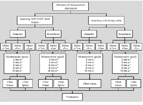
A structure of experimental measuring was prepared for better orientation in the experiment (Figure 4). The structure clearly depicts the methods used for scanning: VAST Gold sensor / RT; monitored parameters – roundness/diameter; a change of the sensor radius Ø1.5/ Ø3/ Ø5; a change of measuring rate; a change of evaluation filter - Spline/Gauss.
Figure 4 Structure of measuring
2.3 The Execution of the Experimental Portion of the Work experimentálnej časti práce
2.3.1 Preparation and Measuring Conditions
The experimental portion of the work was executed on the RONDCOM 60A device and is processed using ACCTeePro software. This software uses the WINDOWS operating system. It is a special software for identifying parameters of surfaces, contours and shape-characteristics of a part [9]. The device scanning system is set at h/2 height, meaning 4.2 mm in the direction of the Z coordinate of the calibration ring and the stylus diameter is 1.5 mm.
The experimental portion of the work was executed using the ZEISS PRISMO Ultra coordinate measuring device with a maximum permitted error in length measurement 0,5+L/350 μm, a fixed VAST Gold sensor and a rotary table. The part was measured using a contact technology of scanning. Results of the experimental measurement are shown in Table 2.
Table 2
Conditions of the surrounding environment Room temperature in the laboratory +20 °C
Relative air humidity 60% ÷ 70%
Reference measuring temperature 20 °C
Sea-level elevation 100 ÷ 125 V: max. 3000 m 230 ÷ 240 V: max. 2000 m
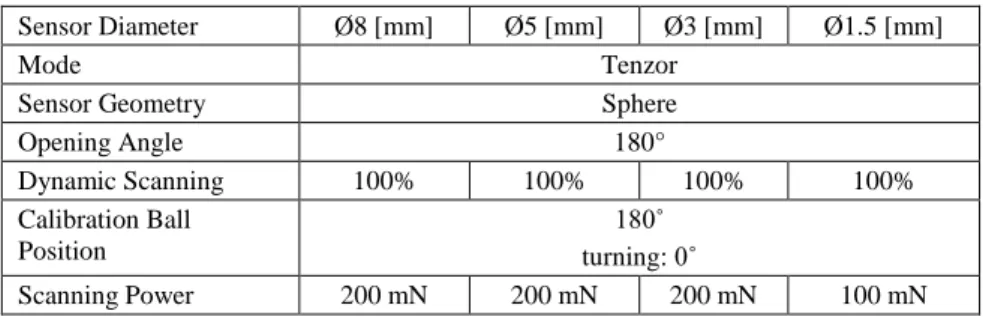
Three scanning stylus of varied diameters were used during the execution of the experiment, according to Table 3. Calibration of scanning systems must be performed in order to achieve precise measurements. The calibration is always performed prior to the measurement of new parts and is intended to correct systemic errors using a calibration ball. The OS_RT scanning system, using a stylus with an 8 mm diameter, is designed for measuring and calibration using a rotary table. Calibration conditions are listed in Table 3.
Identification of sensors in the measuring plan:
DP_ZS_1.5 – stylus with a Ø1.5 mm diameter,
DP_ZS_3 – stylus with a Ø3 mm diameter,
DP_ZS_5 – stylus with a Ø5 diameter.
Basic coordinate systems for the given part must be defined in the software in preparation for the CMM measurement. This process was performed by enabling the positioning of the coordinate system into the center of the calibration ring.
Table 3 Stylus calibration conditions
Sensor Diameter Ø8 [mm] Ø5 [mm] Ø3 [mm] Ø1.5 [mm]
Mode Tenzor
Sensor Geometry Sphere
Opening Angle 180°
Dynamic Scanning 100% 100% 100% 100%
Calibration Ball Position
180˚
turning: 0˚
Scanning Power 200 mN 200 mN 200 mN 100 mN
The measurements of diameter and roundness of the part - calibration ring are performed three times according to the structure stipulated in Figure 4. The measuring plan consisted of the following elements:
Plane 1, Circle 1 – form a basic coordinate system
Circle 2, Circle 4, Circle 6, Circle 8 and Circle 10 – elements intended for measurement with the Ø1.5 mm stylus.
Circle 2_3mm, Circle 4_3mm, Circle 6_3mm, Circle 8_3 mm, Circle 10_3mm - elements intended for measurement with the Ø3 mm stylus.
Circle 2_5mm, Circle 4_5mm, Circle 6_5mm, Circle 8_5 mm, Circle 10_5mm – elements intended for measurement with the Ø5 mm stylus.
The ‘circle’ element must be scanned in order to evaluate roundness. An example of a settings strategy for the measurement of the ‘circle’ element is shown in Figure 5. The following parameters must be set in order to measure this element:
Scanning rate: 2 mm.s-1, 4 mm.s-1, 6 mm.s-1, 8 mm.s-1, 10 mm.s-1.
Number of scanning points: 3000.
Angle range: 380°.
Filter type: Gauss, Spline.
Figure 5 shows an example of the result evaluation settings of the ‘circle’ element measurements and Figure 6 shows filter settings for evaluation. The measurement plan (Fig. 7) is created and applied to the scanning of a ring with the VAST Gold stylus sensor and scanning with the activation of a rotary table. Two measurement plans were created and applied with the exact same conditions for evaluation:
measurement plan for measuring with the VAST Gold fixed stylus without the activation of the rotary table,
measurement plan for measuring with the VAST Gold fixed stylus with the activation of the rotary table (Fig. 7).
Figure 5
Settings strategy and number of scanning points in the CALYPSO interface
Figure 6
Filter settings for evaluation in the CALYPSO interface
Figure 7
Overview of the measurement plan created in the CALYPSO interface: A – Element selection.
B – Measurement characteristics
2.3.2 Execution of the Measurements
The measurement process began with the calibration of the RONDCOM 60A measuring device, calibration of the PRISMO Ultra CMM scanning systems and the calibration of the rotary table that is a part of the PRISMO Ultra CMM and is placed upon the working surface of the device. The calibration of the roundness was performed using gauge blocks (Fig. 8). Calibration process of the Ø1.5; Ø3;
Ø5 and Ø8 mm styli was executed using a ceramic calibration ball of 30 mm diameter. The depiction of the rotary table calibration process using a calibration cylinder is shown in Figure 9. Using the calibration cylinder, the scanning system is able to automatically determine the placing of the rotary table and its parameters.
A B
Figure 8
Calibration of the scanning systems: A – RONDCOM 60A. B - CMM PRISMO Ultra
Figure 9
Calibration of the rotary table: A – calibration proces. B – calibration cylinder. C – Stylus
The calibration Ø25 mm ring was fastened to the rotary table of the RONDCOM 60A circle-measuring device and secured against shifting and turning. The roundness values obtained from the RONDCOM 60A measuring device are established as reference roundness values for the executed experiment. The placement of the calibration ring and the process of measuring roundness and diameter using the PRISMO Ultra CMM is depicted in Figure 10. When measuring with the use of the rotary table, the calibration ring was fastened into
A B
A C
B
the clamps of the rotary table, while in measuring using the fixed VAST Gold stylus, the ring was placed and fastened directly on the measuring table of the device. The final phase of the experiment was the setting off of the plan created in the CALYPSO interface. The scanning of the ring took place automatically through exchanging scanning stylus.
Figure 10
Execution of the measurement:
A - Measurement of the reference value using RONDCOM 60A B - Measurement using the CMM PRISMO Ultra
2.4 Analysis and Evaluation of Results of the Experimental Work
Analysis against data scanned on the calibration ring was performed in order to analyze and evaluate the results of the experimental part of this work.
Figure 11
Measured points in the CALYPSO interface: A - Scanned element; B – Deviation of the ring diameter
A B
A B
A correlation between roundness tolerance and the diameter value declared by the calibration certificate was established for the values obtained from the RONDCOM 60A. After the scanning of the calibration ring, the software evaluated data in both a numeric and graphic form. The CAD window of the software provides a view of the scanned elements (Fig. 11).
2.4.1 Evaluation of Roundness Tolerance
The values measured by the RONDCOM 60A are listed in Table 4. These values were considered basic reference values for the evaluation of the roundness tolerance of the CMM PRISMO Ultra. The results of the experiment of measuring roundness obtained from the CMM PRISMO Ultra are shown in Tables 5 and 6.
Table 4
Measurement of roundness using the RONDCOM 60A – reference values Roundness [μm]
Measurement speed [mm.s-1]
Stylus Ø1.5 mm Filter GAUSS Filter SPLINE
2 0.2650 0.2640
4 0.2710 0.2750
6 0.2730 0.2860
8 0.2800 0.3010
10 0.2880 0.2870
Table 5
Measurement of roundness using fixed VAST Gold stylus scanning Roundness [m]
Measurement speed [mm.s-1]
Stylus Ø1.5 mm Stylus Ø3 mm Stylus Ø5 mm Filter
GAUSS
Filter SPLINE
Filter GAUSS
Filter SPLINE
Filter GAUSS
Filter SPLINE 2 1.2760 1.2789 1.1798 1.1781 1.3686 1.3787 4 1.2592 1.2785 1.1545 1.1699 1.3455 1.3548 6 1.2312 1.2635 1.1741 1.1975 1.3643 1.3723 8 1.2322 1.2580 1.2115 1.2218 1.3872 1.3751 10 1.2368 1.2520 1.2571 1.2609 1.4114 1.4114
Table 6
Measurement of roundness with stylus scanning and a rotary table Roundness [m]
Measurement speed [mm.s-1]
Stylus Ø1.5 mm Stylus Ø3 mm Stylus Ø5 mm Filter
GAUSS
Filter SPLINE
Filter GAUSS
Filter SPLINE
Filter GAUSS
Filter SPLINE 2 1.1898 1.2037 1.1686 1.1433 1.1891 1.2056 4 1.1569 1.1768 1.0197 1.0102 1.1681 1.1705 6 1.1588 1.1818 1.1731 1.1191 1.1874 1.1873 8 1.1969 1.2112 1.1494 1.1092 1.2199 1.2480 10 1.2304 1.2467 1.1713 1.1971 1.2420 1.2540 The following influences were taken into consideration when evaluating roundness tolerance:
The effect of the measuring method on roundness tolerance while changing the scanning rate.
The effects of the scanning stylus diameter on roundness tolerance while changing the scanning rate.
The effect of the filter on roundness tolerance while changing the scanning rate.
The relations are shown graphically in Figure 12 a, b, c, d.
Figure 12
Evaluation of Roundness Tolerance: A – Scanning by VAST Gold sensor – filter Gauss. B – Scanning by VAST Gold sensor – filter Spline. C – Rotary table – filter Gauss. D – Rotary table – filter Spline
A
Figure 12
Evaluation of Roundness Tolerance: A – Scanning by VAST Gold sensor – filter Gauss. B – Scanning by VAST Gold sensor – filter Spline. C – Rotary table – filter Gauss. D – Rotary table – filter Spline
B
C
D
2.4.2 Diameter Measurement
The results of the experiment of diameter measurement measured using the CMM PRISMO Ultra are shown in Tables 7 and 8. The 25.0049 mm reference diameter of the ring was used based on the calibration certificate.
Table 7
Diameter measurement using the fixed VAST Gold stylus scanning Diameter of ring [mm]
Measurement speed [mm.s-1]
Stylus Ø1.5 mm Stylus Ø3 mm Stylus Ø5 mm Filter
GAUSS
Filter SPLINE
Filter GAUSS
Filter SPLINE
Filter GAUSS
Filter SPLINE 2 25.00497 25.00496 25.00503 25.00503 25.00482 25.00482 4 25.00493 25.00493 25.00502 25.00502 25.00482 25.00482 6 25.00493 25.00493 25.00502 25.00502 25.00481 25.00481 8 25.00492 25.00491 25.00488 25.00488 25.00480 25.00480 10 25.00488 25.00488 25.00497 25.00497 25.00479 25.00479
Table 8
Diameter measurement using rotary table scanning Diameter of ring [mm]
Measurement speed [mm.s-1]
Stylus Ø1.5 mm Stylus Ø3 mm Stylus Ø5 mm Filter GAUSS Filter GAUSS Filter GAUSS
2 25.00713 25.00628 25.00284
4 25.00715 25.00637 25.00297
6 25.00716 25.00639 25.00307
8 25.00716 25.00641 25.00311
10 25.00717 25.00642 25.00311
The following influences were taken into consideration when evaluating the diameter measurement:
The effect of the measuring method on diameter measurement while changing the scanning rate.
The effect of the filter on diameter measurement while changing the scanning rate.
The effects of the scanning VAST Gold stylus diameter on diameter measurement while changing the scanning rate.
The relations are shown graphically in Figure 13 a, b, c.
Figure 13
Evaluation of the Diameter: A – Scanning by VAST Gold sensor – filter Gauss. B – Scanning by VAST Gold sensor – filter Spline. C – Rotary table – filter Gauss
A
C B
Evaluation and Conclusion
The evaluation of the extensive experiment is divided into three parts. The first part evaluates the effect of the method of measurement, the effect of the scanning stylus and the effect of the filter on the assessment of the roundness tolerance. In the second part of the evaluation, the effect of method, scanning stylus diameter and filter were established for the assessment of diameter. The last part focuses on a comparison of the graphic representation of roundness.
Roundness evaluation:
Effect of the method of measurement: measurement using a rotary table better corresponded to the reference value compared to the VAST Gold sensor method.
However, the difference of roundness between both methods of measurement is within the range of (0 ÷ 0.2) μm.
Effect of the stylus diameter: The results from the Ø3 mm diameter best correspond with the declared etalon value. The difference in the result when measuring by Ø1.5 mm, Ø3 mm and Ø5 mm stylus is (0.1 ÷ 0.4) μm.
Effect of the filter: The Gauss and Spline filter does not have a significant effect on roundness measurement. The maximum difference was recorded when measuring with the VAST Gold stylus at the rate of 6 mm.s-1 with Ø1.5 mm diameter. The difference of measured values in this case was 0.0323 μm. The best corresponding values for different filter evaluation were achieved in measuring roundness with a Ø3 mm stylus and the VAST Gold sensor.
Effect of scanning rate: The rate of 4 mm.s-1 was established as the most suitable scanning rate in measuring with the rotary table and using a Ø3 mm stylus. The difference in roundness between the reference value and measured value for the Spline filter was 0.7402 m and for the Gauss filter 0.7497m.
Graphic Comparison of Roundness
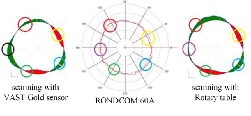
Figure 14
Graphic comparison of roundness. Scanning rate: 2 mm.s-1_filter: GAUSS
Graphic results of the measurement show Figure 14 that the method of stylus scanning using a rotary table better corresponds with graphic results obtained using the RONDCOM 60A device. Circles identify similar areas in the same color. An area identified by a black circle indicates the least corresponding value.
Evaluation of the Diameter:
Effect of the method: The method of stylus scanning with the VAST Gold sensor best corresponds with the etalon value and is therefore more suitable than measurement using a rotary table.
Effect of the scanning stylus diameter: Values closest to the reference values were measured using the VAST Gold sensor at the scanning rate of 6 to 10 mm.s-1 with the Ø1.5 mm stylus diameter. Diversion from the reference value at this scanning rate was a maximum of 0.03 μm.
Effect of the filter: The comparison of the Gauss and Spline filters shows negligible differences in the measurement results. When scanning using the VAST Gold sensor, the recorded divergences were in the range of (0 ÷ 0.02) μm. With the increase of scanning rate using the VAST Gold sensor, the measured values had a decreasing tendency. When measuring using the rotary table, the measured values had the opposite tendency, meaning that the measured diameter values increased with the increasing scanning rate.
As is apparent from this experiment, to precisely evaluate roundness, the best option is to use measurement with a rotary table, Ø3 mm stylus diameter, 4 mm.s-1 scanning rate and the Spline filter. To measure diameter, the most suitable combination is VAST Gold sensor with an Ø1.5 mm stylus diameter, 6 to 8 mm.s-1 scanning rate and the Spline filter. However, the use of the Gauss filter does not indicate significant differences for evaluating a diameter.
Acknowledgements
This contribution is a part of the VEGA project of Ministry of Education, Science, Research and Sport of the Slovak Republic, No. 1/0477/14 “Research of influence of selected characteristics of machining process on achieved quality of machined surface and problem free assembly using high Technologies” and the project Technical research and development infrastructure for contact and non-contact measurement methods“, ITMS 26210120020, the Operational Program Research and Development financed by the European Regional Development Fund".
We support research activities in Slovakia / project is co-financed from EU funds.
References
[1] W. Xingsheng, X. Jieyu, Y. Yong, Z. Yongnian, F. Xiuqing, K. Min: Use of Coordinate Measuring Machine to Measure Circular Aperture Complex Optical Surface, Measurement, Vol. 100, 2017, pp. 1-6, ISSN 0263-2241, https://doi.org/10.1016/j.measurement.2016.12.038
[2] A. Keck, O. Sawodny, M. Gronle, T. Haist, W. Osten: Active Compensation of Dynamic Errors in a Coordinate-Measuring Machine, IFAC-PapersOnLine, Vol. 49, Issue 21, 2016, pp. 636-641, ISSN 2405- 8963, https://doi.org/10.1016/j.ifacol.2016.10.672
[3] Syed Hammad Mian, Abdulrahman Al-Ahmari: Enhance Performance of Inspection Process on Coordinate Measuring Machine, Measurement, Vol.
47, 2014, pp. 78-91, ISSN 0263-2241,
https://doi.org/10.1016/j.measurement.2013.08.045
[4] Z. He, J. Fu, X. Zhang, H. Shen: A Uniform Expression Model for Volumetric Errors of Machine Tools. International Journal of Machine Tools and Manufacture. Volume 100, January 2016, Pages 93-104
[5] D. H. Genest, Brown & Sharpe Manufacturing Company: Coordinate Measuring Machines. In ASM Handbook, Vol. 17, 1989. pp. 18-28
[6] A. Gąska, J. Sładek, K. Ostrowska, R. Kupiec, M. Krawczyk, W.
Harmatys, P. Gąska, M. Gruza, D. Owczarek, R. Knapik, A. Kmita:
Analysis of Changes in Coordinate Measuring Machines Accuracy Made by Different Nodes Density in Geometrical Errors Correction Matrix, Measurement, Vol. 68, 2015, pp. 155-163, ISSN 0263-2241, https://doi.org/10.1016/j.measurement.2015.02.056
[7] D. Zhao, Y. Bi, Y. Ke: An Efficient Error Compensation Method for Coordinated CNC Five-Axis Machine Tools, International Journal of Machine Tools and Manufacture, Vol. 123, 2017, pp. 105-115, ISSN 0890- 6955, https://doi.org/10.1016/j.ijmachtools.2017.08.007
[8] J. Dupuis, C. Holst, H. Kuhlmann: Improving the Kinematic Calibration of a Coordinate Measuring Arm Using Configuration Analysis, Precision Engineering, Vol. 50, 2017, pp. 171-182, ISSN 0141-6359, https://doi.org/10.1016/j.precisioneng.2017.05.004
[9] ACCTee PRO. 2014 Available on: <http://www. zeiss .com /industrial- metrology/ende/products/systems/form-andsurface/>
[10] Š. Kender, Súradnicové meracie stroje, In Electronic magazine Transfer of innovation, TU Košice, Vol. 26, 2013 Available
on:<https://www.sjf.tuke.sk/transferinovacii/pages/archiv/transfer/26- 2013/pdf/233-235.pdf>
[11] ZEISS PRISMO, 2017 Available on:
<https://www.zeiss.sk/metrologia/produkty/systemy/bridge-type- cmms/prismo.html>
[12] D. Flack: Measurement Good Practice Guide No. 43, Queen's Printer, Scotland, 2014.ISSN 1368-6550