Loading Surface in the Course of Mechanical- Thermal Treatment and Steady-State Creep of Metals
Andrew Rusinko
Óbuda University
Népszínház utca 8, H-1081 Budapest, Hungary E-mail: rusinko.endre@bgk.uni-obuda.hu
Abstract: Kinetics of the loading surface of a material gives precious information on the level of the hardening of the material. This paper is concerned with the evolution of the loading surface during successive actions, such as: (i) plastic deformation, (ii) annealing of the pre-strained specimen, and (iii) secondary creep of the treated material. The analysis of the loading surface is carried out in terms of the synthetic theory of irrecoverable deformation.
Keywords: loading surface; mechanical-thermal treatment; creep and plastic strain;
synthetic theory of irrecoverable deformation
1 Introduction
Numerous experiments testify that mechanical-thermal treatment (MTT) is an effective tool to improve the strength of metals [2, 4, 9, 10]. MTT involves (i) plastic deformation of a specimen at room temperature (T0), e.g. in uniaxial tension (we give the acting stress symbol
σx0 and we will mark as
εx0 the plastic strain induced by
σx0), and (ii) annealing of the cold-worked specimen in unloaded state (let us denote the annealing temperature and duration as T1 and t1, respectively). As seen in Figures 1 and 2, if we subject the treated specimens to creep with stress σx and temperature T2, the creep rate (εx) is not a monotonous function of the plastic pre-strain
εx0 (with the proviso that the values of σx, T2, T1, and t1 are unchangeable). Figure 1 demonstrates the steady-state creep rate εx (σx 25MPa,T2700C) of Ni+1.18% alloy against plastic pre-strain at room temperature
εx0 developed in the course of preliminary MTT (the annealing temperature and duration T1T2 700C and t11hour,
respectively). Figure 2 shows the steady-state creep rate (σx15MPa, C
2500
T ) of copper as a function of plastic pre-strain at room temperature developed in MTT (T1T2500C, t11hour). In these figures, the points are the experiment [2,4], and the solid line is the analytical curve.
According to Figures 1 and 2, there exists an optimal level of plastic pre-straining after which (with intermediate annealing) the rate of stationary creep is minimal.
The existence of different types of behavior of the tested specimens subjected to creep is connected with distinctions in the initial structure of the material formed as a result of plastic pre-straining and annealing. Indeed, the structure affects the intensity of the processes of polygonization and recrystallization, which control the rate of stationary creep.
Figure 1
Steady-state creep rate of Ni+1.18% alloy against plastic pre-strain
Figure 2
Dependence of the steady-state creep rate of copper on the level of preliminarily induced plastic strains
Another positive effect of MTT is an increase in the duration of the secondary creep [2,4], which can be concluded from cavities nucleation and development [3].
0,%
x
1 7,s εx10
Due to a plastic strain, the initial (relatively perfect) crystals suffer fragmentation and the sizes and orientation of fragments depend on the level of strains. The boundaries between the fragments form a three-dimensional grid of dislocations which can be regarded as a pileup of dislocations. Subsequent annealing ambiguously affects the preliminarily formed dislocation structure promoting the initiation of the thermally controlled processes of polygonization and recrystallization. The course of one of these processes depends on the level of pre- straining and the temperature of annealing [5-7, 12].
In the case of annealing of an insignificantly cold-hardened material, we observe the redistribution of dislocations of the same sign in the form of rearrangement into vertical walls. As a result, poorly formed cells appearing as a result of plastic deformation become completely surrounded with low-angle boundaries and gradually turn into well-formed subgrains in the body of which the density of dislocations is lower than in the deformed matrix. The higher (to a certain degree) the value of plastic pre-straining, the greater the number of appearing subgrains, i.e., the higher the intensity of polygonization. The polygonized structure formed in the process of preliminary TMT decreases the level of sliding (both coarse and fine) in testing for creep. This fact can be explained by the restriction of the free path of dislocations imposed by the preliminarily formed grid of subgrain boundaries.
In the case of annealing of a material with relatively high plastic strains, the density of dislocations built in the subgrain boundaries increases and, hence, the angle of their mutual orientation also increases. It is known that subgrains with large-angle boundaries play the role of centers of recrystallization, i.e., of the formation and growth of grains with more perfect structure. In the course of recrystallization, the resistance of the metal to plastic deformation significantly decreases since the rapid migration of the boundaries intensely “cleans” the deformed matrix, which facilitates the motion of dislocations under conditions of creep and increases the rate of stationary creep as compared with its optimal value. Thus, the optimal degree of plastic pre-straining should be chosen to avoid the possibility of intense recrystallization.
Classic theories such as ageing (time-hardening) theory, flow theory, and strain- hardening theory [1] are incapable of the modeling of the dependence
ε 0εx f x due to the fact that, in terms of these theories, the creep rate is related to the acting stresses and the loading-prehistory is ignored. This fact motivates the author to model the effect of MTT utilizing a more efficient model able to embrace a wider circle of processes and their interplay: the synthetic theory of irrecoverable deformation (ST).
2 Mathematical Apparatus: Synthetic Theory
The analytical description of the dependence of steady-state creep rate εx on the plastic pre-strain
εx0 in the course of MTT is carried out in terms of the synthetic theory of irrecoverable deformation [8-11]. The yield limit of a material in the three-dimensional subspace (R3) of five-dimensional stress deviator space has the shape of a sphere, which correspond to the von-Mises yield criterion:
2 2
3 2 2 2
1 S S 23σT
S (1)
where σT, depending on the problem considered, is the yield limit (σS) or the creep limit (σS) of the material; Si(i1,2,3) are coordinate axes in R3.
In terms of ST, the yield/loading surface is constructed as the inner envelope of tangent planes. In the virgin state, sphere (1) is the inner envelope of tangent planes, which are equidistant to the origin of coordinate in all directions. A loading is presented by a stress-vector, S
, whose components are defined in [8, 11]. As the stress-vector grows, it translates on its endpoint tangent planes (the orientation of tangent plane does not vary during the motion). The planes which are not reached by S
remain stationary. The displacement of a plane symbolizes the increment in plastic deformation (plastic slip) within an appropriate slip system at a point of a body. The plastic strain developed within one slip system defines a microlevel of deformation. The total strain (macrostrain) is calculated by the summation (threefold integrals) of the microstrains occurring in activated slip systems.
Consider the case of uniaxial tension when the components of S are S1 23σx, S20, S30 [8]. As S 23σS
, there is only one plane tangential to the sphere (1) reached by the vector S
, and it is perpendicular to the S
. During further elongation of the S
, new planes become located on the endpoint of the stress-vector and – following the rule that a loading surface is the inner envelope of planes – the loading surface take the shape of a cone symmetric relative to the S1-axis, and its generator is constituted of the boundary tangent planes reached by the stress-vector. This cone goes over to the initial sphere in the directions where tangent planes remain immovable.
The plastic strain component in uniaxial tension, e1, is calculated as [8-11]
λ β α
1 1 φ sinβcosβcosλ β λ d r d
e N , e2 0, e3 0, (2)
where φN is referred to as irrecoverable strain intensity (index N stands for the vector normal to the tangent plane, which gives the orientation of the plane), which is defined by the following differential equation
dt K rd
dψN φN ψN , (3)
where φN is called defects intensity; dt is the time differential, r is the constant of material, and K is a function of the homological temperature and current stresses:
23σ
3exp 2 1
K K x
K
K , (4)
where Ki (i1,2,3) are the material constants.
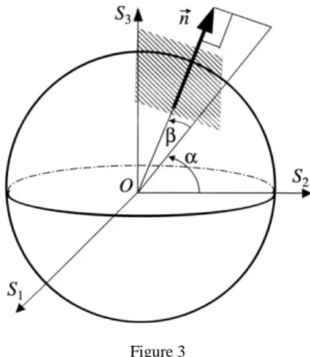
Figure 3 Orientation of the normal n
in the subspace R3 The defects intensity, according to [8, 9], is
2 2 23σ
ψN HN T , HN SN Sncosλ23σxsinβcosλ
, (5)
where HN (i1,2,3) is a distance to the plane reached by stress-vector; angle β gives the orientation of a plane in R3 (the role of angle λ, which is immaterial within this article, can be found in [8]). In general, the orientation of the normal in R3, n
sinβ,cosαcosβ,sinαcosβ
, is shown in Figure 3. The magnitude of HN shows the degree of the hardening of material. Actually, the greater theHN, the greater the stress-vector needed to reach the plane.
When calculating “immediate” plastic deformation (dt0), the formula takes the form
N
N rφ
ψ . (6)
For the case of secondary creep (ψN 0), from (3) we have r
K N
N ψ
φ . (7)
The steady-state creep rate strain component is expressed by the relationship where the integrand is φN.
If annealing a work-hardened specimen in an unloaded state (dφ0), the formula yields
dt K
dψN ψN . (8)
The solution of differential equation (8) is
Kt NN ψ exp
ψ 0 ,
where
ψN0 is the defects intensity in the work-hardened material. Therefore, on account of formula (5), the distance to the planes after the plastic deformation and annealing is
22 ψN0 exp 23σT
N Kt
H . (9)
Formula (9) expresses the motion of the planes toward the origin of coordinates.
This motion for each plane will terminate as it touches the sphere (1).
3 The Generalization of the Synthetic Theory to the Case of MTT
To evaluate the steady-state creep rate of a metal after MTT, we replace formulae (5) and (4) by
2 ψ 2
N N TN
M H H , (10)
, max
1exp
2
maxK3M f H K K H
K , (11)
where TN
H is the distance to a plane after MTT, which characterizes the thermal stability of the polygonization structure against the recrystallization during creep.
In the absence of MTT, T P
H N 23σ and the relation for MN
ψ from (10) degenerates to (5). In formula (10), Hmax is the maximal distance to planes for the whole loading history at a given temperature.
3.1 Tension of Specimen at Room Temperature
The plastic strain component, 10
e , is calculated as [8]
0
0 0 1
1 a sinβ
e , a0 πσS2
9r ,0 σ σ 0
β
sin 1 S x , (12)
2 4 2
2 2 2
ξ 1 ξ
ξ 1 ln1 ξ ξ 3 ξ 1 ξ 5 1 2 ξ)
(
. (13)
The loading surface is shown in Figure 4a. The value of Hmax in the plastic loading can be obtained from (5) at βπ2, λ0.
3.2 Annealing of Deformed Specimen
Consider the case when the annealing temperature coincides with the temperature of the following creep: T1T2.
As seen from (5), the heating of the specimen to the temperature T1 results in a decrease of HN due to a drop in the value of σT caused by the temperature gradient. Since the temperatures of annealing and creep are assumed to be equal, the effect of MTT on the steady-state creep rate can be revealed by studying the positions of tangent planes relative to the value of σP at TT1. If we ignore an immaterial duration of the heating from T0 to T1, the decrease in HN can be assumed to be of a step-wise nature, which symbolizes the step-wise motions of planes toward the origin of coordinates. This fact means that the values of angles
10
λ and 10
β remain unchangeable during annealing. Therefore, formula (9) at
0
t takes the form
λ λ β , β π 2 σ
λ λ 0 , π 2 β β σ , σ λ βcos σ sin 3 2
0 0
0 0
0
1 2 1
1 2 1
2 2 2
P S P x
HN . (14)
Consider the distance from the origin of coordinates to the point of intersection of tangent plane with S1-axis, L
β,λ,t
. For simplicity, while not distorting the result, we study the value of L at λ0. From Figure 4a it follows that
β,t HN sinβL . (15)
In active loading, L
β const 23σx0 for β10 βπ 2. The value of L due to the temperature decrease, TT1T0, according to (14) and (15), is
σ
σ σ
sin β3 0 2
β, 2 2 2 2 2
0 S P
t x
L , β10 βπ 2. (16)
As seen from formula (16), the loading surface maintains its shape but the tangent planes from the range β10 βπ 2 are not on the cone tip (Figure 4b).
During annealing, according to (9), (11), and (15), we have
2 2 2 2
2 σ sin β σ exp σ
3 2
0 S M P
N x K t
H . (17)
σ exp
σ exp
σ
sin β3 , 2
β 2 2 2 2 2
0 M S M P
x K t K t
t
L , β10 βπ 2. (18)
Distance TN
H is determined by Eq. (17) at tt1.
The presence of KM in (17) makes it possible to describe the displacement of planes even in a load-free state. Indeed, since the distance Hmax appearing in the definition of KM (14) is non-zero (Hmax σx0 0), formula (17) governs the displacement of planes during the annealing as σx0. Another important feature of KM is that the intensity of the displacements depends, via
σx0, on the level of plastic pre-strain.
The behavior of function L
β at tt1 depends on the relationships between the values of σ2Sexp
KMt1
and σ2P. If σ2Sexp
KMt1
σ2P, L
β grows with increasing β , L'
β 0. Otherwise, L
β is a decreasing function of β .The fact that L'
β 0 means that, during the annealing, the planes from the directions β β π 210 travel such distances toward the origin of coordinates that their points of intersection with S1-axis lie to the right to the cone tip.
Therefore, it can be concluded that the loading surface at the end of annealing (tt1) retains the shape formed at t0.
If σ2Sexp
KMt1
σ2P, L()=const, i.e. the loading surface has a form of cone on whose tip there are all the planes that were reached by stress vector at plastic loading. The decreasing dependence of L
β on β means that the loading surface, being the inner envelope of tangent planes, loses the angular point (Figure 4c).Figure 4
Evolution of loading surface in the course of preliminary MTT and subsequent creep (boundary planes are shown only)
S1
S1
S1
S2
S2
S2
S2
O
O
O σS 3 2
σP 3 2
σP 3 2
σP 3 2 a)
d) c) b)
L(=10) L()=const
L(=10) L(=/2)
L(=/2)
10
10
10
1
S1
S S0
3.3 Steady-State Creep of Metal Treated by MTT
The loading surface in creep (σx
t const), similarly to a plastic deformation, has a shape of a cone (Figure 4d) which does not vary in time. InsertTN
H into (6):
λ β, σ
λ βcos σ sin
λ β, σ ,
σ exp λ βcos σ sin λ βcos σ sin 3 ψ 2
2 1 2
2 1 2 1
2 2
0 0
x P
M P x S
M x
t K
N , (19)
where 10
β,λ is the range of angles β and λ: β10 βπ 2,10
λ λ 0 ;
β,λ1 stands for
10
1 β β
β , λ10 λλ1. Here we restrict ourselves to the case when the creep stress vector S
is such that the range 1
β,λ is greater than
β,λ 10 . As such, the values of λ1 and β1 are calculated by equating the MN
ψ and λ from 1 1
β,λ to zero [8, 11]:
σ sinβ
σ β) λ (
cos 1 P x , sinβ1σP σx. (20)
It must be noted that the loading surface in creep without preliminary MTT is formed by the same set of tangent planes, 1
β,λ . However, the planes from the diapason 10
β,λ travel greater distances on the endpoint of the Sthan those for the treated material.
The creep strain rate after MMT, e1M, is determined by formulae (20), (19), (7), and (2):
2 π/ β
2 2 λ
0 1
2 π/
β
2 2 λ
0 1
10 0 10
1 1
β λ cosλ cosβ sinβ σ cosλ sinβ exp σ
β λ λ βcos βcos σ sin λ βcos σ sin 3
π~ 4
d d t
K
d r d
e K
x S M
x P
M
. (21)
According to (5) and (2), the first integral in (21) gives the creep rate without MTT, e1a
sin
β1
, aπσ2P
9r , and the second one does the preliminary plastic strain10
e (formulae (12) and (13)). Therefore,
10 1
10 11 ~exp
e t e K K e
eM M , (22)
where the K~const
is obtained from Eq. (11) at Hmax 23σx const. For the case when MTT is not carried out, we have e10 0 and e1M e1. With an increase of pre-strain, the term ~exp
10 1
10e t e K
K M first increases and then tends to zero.
On the basis of formula (22), in Figure 1 and 2, the analytical and experimental [2, 4] curves e1M f
e10 are plotted. Good agreement between the analytical and experimental data enables us to use formula (22) to predict the steady-state creep of metals as a function of preliminary plastic deformation in the course of MTT.Conclusions
The analysis of the evolution of loading surface in the course of mechanical- thermal treatment and subsequent steady-state creep has been studied. Depending on the value of plastic pre-strain, in the course of MTT, the loading surface can assume a conic or rounded shape. The analytical results give good agreements with experimental data.
Acknowledgement
The author expresses thanks to Prof. K. Rusinko (Budapest University of Technology and Economics, Hungary) for many useful conversations on the topics presented in this article.
References
[1] Cadek, J. (1988) Creep in metallic materials, Elsevier
[2] Bazelyuk, G., Kozyrskii, G., Petrunin, G., Polotskii, I. (1970) Influence of Preliminary Ultrasonic Irradiation on the High-Temperature Creep and Microhardness of Copper, Fiz. Metal. Metalloved., 29: 508-511 (in Russian)
[3] Devenyi, L., Biro, T. (2003) Investigation of Creep Cavities by Scanning Electron Microscope, Materials Science Forum, 414-415: 183-187
[4] Kozyrskij, G., Kononenko, V. (1966) The Study of the Creep of Prestrained Nickel Alloy, Fizika metallov i metallovedenije, 22: 108-111 (in Russian) [5] Reger, M., Vero, B., Felde, I., Kardos, I. (2010) The Effect of Heat
Treatment on the Stability of Centerline Segregation, Strojniski vestnik – Journal of mechanical engineering, 56: 143-149
[6] Reger, M., Vero, B., Csepeli, Zs., Pan, J. (2004) Modeling of Intercritical Heat Treatment of DP and TRIP Steels, Transaction of Materials and Heat Treatment, 25: 710-715
[7] Réger, M., Louhenkilpi, S. (2003) Characterizing of the Inner Structure of Continuously Cast Sections by Using of Heat Transfer Model, Materials Science Forum 414-5: 461-469
[8] Rusinko, A., Rusinko, K. (2011) Plasticity and Creep of Metals, Springer [9] Rusinko, A. (2002) Analytic Dependence of the Rate of Stationary Creep
of Metals on the Level of Plastic Prestrain, J. Strength of Metals 34: 381- 389
[10] Ruszinko, E. (2009) The Influence of Preliminary Mechanical-Thermal Treatment on the Plastic and Creep Deformation of Turbine Disks, MECCANICA 44: 13-25
[11] Rusinko, A. (2010) Non-Classical Problems of Irreversible Deformation in Terms of the Synthetic Theory, Acta Polytechnica Hungarica 7: 25-62 [12] Totten, G. E. (2006) Steel Heat Treatment: Metallurgy and Technologies,
Taylor & Francis