Keneth 0. Parker* and Robert A. Stone
AiResearch Manufacturing Company, Los Angeles, Calif.
Abstract
This paper presents the results of a design study of the Spur radiator. Factors affecting the choice of materials and fabrication procedures are discussed, and the require- ments imposed on the radiator by the rest of the system are
described. The results of parametric studies that show the effect on the radiator of the important design variables are given. A reference design of a 350-kwe system radiator is described in detail. It is made entirely of columbium - 1$
zirconium alloy and weighs 5 lb/kwe, with an area of 1-1/2 ft
2/kwe for the condenser section and 1/2 ft
2/kwe for the subcooler. The weight includes manifolds and structure to support the reactor and shield and is based on what is be- lieved to be a reasonable system of meteoroid parameters.
Nomenclature A = radiating area, ft
2Av = area vulnerable to meteoroid damage, ft
a = coefficient defined by Eq. (10), number/m
2-sec b = coefficient defined by Eq. (10)
C = sonic velocity in meteoroid armor, fps d = meteoroid diameter, cm
E = elastic modulus of meteoroid armor, lbf/in
2F = thin target factor, defined by Eq. (8), dimensionless g = conversion factor, 32.2 1b-m-ft/1bf-sec
2K = coefficient defined by Eq. (15) k = coefficient defined by Eq. (6)
k
f= fin thermal conductivity, Btu/hr-ft-°F L = condenser tube length, ft
JL = fin width, ft
M = radiation modulus, dimensionless r M = meteoroid visual magnitude
Presented at the ARS Space Power Systems Conference, Santa Monica, Calif., September 25-28, 1962.
*Project Engineer.
/Preliminary Design Engineer*
m i meteoroid mass, g
P = static pressure, lbf/ft
2P( o) = probability of no system failure due to meteoroid damage
p = meteoroid penetration in thick target, cm Q, = radiator heat rejection rate, Btu/hr Re = Reynolds number
T = temperature, °R
t = thickness required for meteoroid armor, cm t
f= fin thickness, ft
u = vapor velocity, fps V = meteoroid velocity, fps
€ = radiator surface emissivity, dimensionless
X) = radiator fin effectiveness, dimens ionl essv = kinematic viscosity, ft
2/hr
p = density, g/cm
3, except lbm/ft
3in Eq. (20) a = Stefan-Bol tzmann constant, 0.171 x Ю "
8Btu/hr-ft
2-(°R) *
T = time of exposure to meteoroids, yr
0 = meteoroid flux of visual magnitude m orgreater, number/m -sec
\|f = meteoroid damaging flux, number/m -sec Subscr
E e g
1m = o
t s
[£tS.
effect ive
exit condition of fluid gas
1 iqu i d meteoroi d
entrance condition of fluid s ink
target
1. Int roduct ion
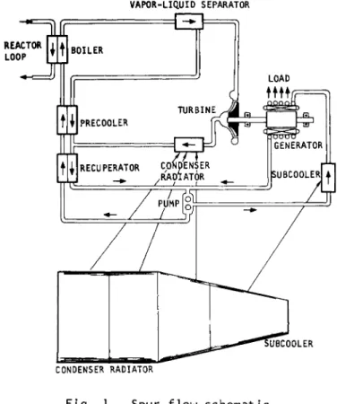
The Spur system, a 350-to-l000 kwe powerplant currently under development by AiResearch Manufacturing Company for the Aeronautical Systems Division, U.S. A i r Force, uses a potassium Rankine cycle t o convert t h e heat from a fast reactor to electrical energy.
A flow schematic is shown in Fig. 1. In t h e 350-kwe size, approximately 2.5 Mw of thermal energy is transferred from the reactor to t h e potassium boiler by t h e reactor fluid.
The wet vapor leaving t h e boiler flows t o the vapor-liquid
separator, where the liquid is removed and then mixed ^ith
produced by the directly connected generator. The wet vapor from the turbine is condensed at 1300° to 1400°F in the radi- ator with the rejection of about 2 Mw of waste heat. A cool-
ing circuit, interconnected with the system circuit at the pump, is used to provide a low-temperature cooling fluid to the generator, bearings, and pump. This heat, about 80 kw,
is rejected in the subcooling radiator at 575° to 700°F.
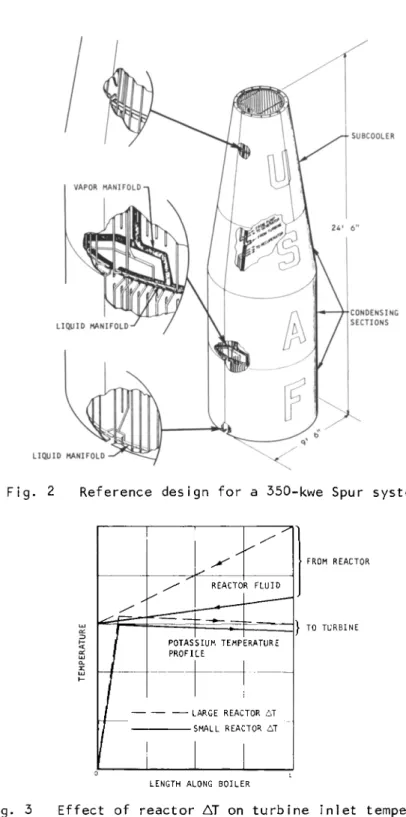
The radiator reference design for a 350-kwe system is shown in Fig. 2. The tube-and-fin radiator, fabricated from a col- u.Tibium alloy, weighs approximately 1700 lb, including manifolds and structure. This design, capable of supporting the reactor and shield through launch, is shielded fully from the reactor to prevent scattering of radiation to the payload.
Table 1 lists some of the specific design information for the reference design. The bases for this design are discussed below under general headings of System Considerations, Meteo- roid Considerations, Parametric Studies, and Material and Fabrication Considerations.
2. Effect of System Considerations on the Radiator Radiator Temperature
The principal incentive for high temperature in space power systems is to minimize radiator area, which is proportional to radiator temperature to the fourth power. The optimum radiator temperature, determined primarily by the reactor inlet temperature, is essentially independent of conditions at the reactor outlet, where the highest fluid temperature
in the system occurs. The reason for this is seen in Fig. 3.
The peak boiling temperature is limited to reactor inlet tem- perature; raising the reactor AT at constant inlet conditions has little or no effect on boiler exit, or turbine inlet temperature. The radiator temperature for minimum radiating area for Rankine cycle systems is determined by the turbine
inlet temperature and is always near three quarters of the absolute turbine inlet temperature. For the Spur cycle, the ratio of radiator inlet temperature to turbine inlet tempera- ture is 0.78.
Subcooler Requirements
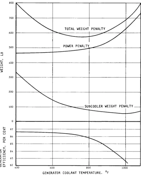
Subcooling of the working fluid is required to provide a low-temperature generator coolant stream. The Spur generator efficiency varies with temperature, as shown in Fig. 4.
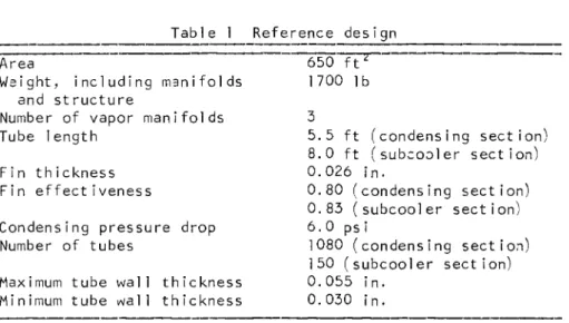
Table 1 Reference design Area 650 ft"
Weight, including manifolds 1700 lb and structure
Number of vapor manifolds 3
Tube length 5.5 ft (condensing section) 8.0 ft (subcooler section) Fin thickness 0.026 in.
Fin effectiveness 0.80 (condensing section) 0.83 (subcooler section) Condensing pressure drop 6.0 ps ï
Number of tubes 1080 (condensing section) 150 (subcooler section) Maximum tube wall thickness 0.055 in.
Minimum tube wall thickness 0.030 in.
The inefficiencies of the generator must be removed at the generator temperature; although, at low temperature the in- efficiencies are small, the low temperature requires a very large radiator. As the generator temperature is increased, the inefficiencies at first increase more slowly than T4, and then more rapidly at higher temperatures. Thus, the subcooler area goes through a minimum. For the Spur system, this point of minimum subcooler area occurs above 1000 F.
Subcooler area is not the only consideration, however, since there is a weight and area cost of power required to operate the generator at reduced efficiency. In Fig. 4, the trade- off of generator temperature is plotted with a 10-1b/kwe-power penalty and a radiator weight of 2 lb/ft2. It is seen that the curve goes through a board flat minimum range between 600° and 800°F. On this basis, 600°F was chosen as the gene-
rator temperature. The very slight weight penalty for opera- ting at this temperature is more than offset by the relative ease of developing a generator for operation at 600° rather than 800°F. The subcooler liquid also is used to cool the pumps and bearings; although quantitative information similar to that developed for the generator is not available, a tem- perature of 600° rather than 800°F is preferred for these components.
Use of Recuperator
As described in the foregoing, a supply of subcooled liquid at about 600°F is required for generator and bearing coolant.
A recuperative heat exchanger is used to cool the condensate
to the boiler feed stream. A trade-off exists between recuperator effectiveness and subcooler-radiator area.
A low effectiveness recuperator has a large AT between hot and cold streams; this ДТ corresponds to a heat load on the subcooler. In the Spur system the optimum recuper- ator effectiveness is 0.95, corresponding to a AT of 30°F and to a subcooler heat load of about 19 kw. This means that about 20$ of the total subcooler area is required to provide a temperature difference to the recuperator.
Shielding Considerations
As a general ru1e, the radiator in a nuclear space power system must be shadowed completely from the reactor by a shield to prevent nuclear radiation from being scattered off the radiator and damaging the payload. Scattered ra- diation can be much more severe than direct radiation that has been attenuated by a shield. For example, the Spur shield will be required to attenuate the neutron flux from the reactor by a factor of about Ю5 for instrument payloads.
Then, if only Ю "5 of the reactor neutron leakage were scat- tered by the radiator to the payload, the neutron dose from scattered radiation would be as great as the direct dose.
Actually, the fraction of scattered radiation would be Ю "4 or higher for radiators that have been considered for this type of system; therefore, complete shadowing of the radiator
is necessary.
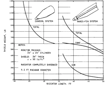
The shield will generally be conical, with the cone angle determined by the overall package length of the power system.
Small shields correspond to small cone angles and, consequen- tly, large package lengths. Fig. 5 shows the variation of shield weight with radiator length. It is assumed that the reactor package to be shielded is a cylinder, 24 in. in dia- meter and 24 in. in height. The shield is assumed to weigh 50 lb/ft3 and to be 26 in. thick. These numbers, based on extrapolations of unclassified Snap program literature, are used to illustrate the analysis required. The maximum dia- meter of the power system, or of the radiator, is 10 ft.
It is seen from Fig. 5 that the shield weight for a 35-ft conical radiator is about 600 lb. To reduce the radiator
length to 23 ft, the shield weight increases to 1300 lb.
It is difficult at this time to place a quantitative number on the desirability of a shorter power system. It appears from the curve that a radiator length in the neighborhood of 25 to 30 ft and a shield weight of 650 to 950 lb is not too far from the optimum condition. Fig. 5 also shows the shield weight vs radiator length for the three-fin radiator
configuration shown. Here it is possible to save some of the shield weight, since only the radiator fins need shield-
ing, not the entire circumference of the radiator. The basic shield configuration assumed with the three-fin radiator is a cone shadowing the payload, located directly aft of the ra- diator, with "ears" that shadow the radiator fins. It is seen that, for short radiator lengths, so-called "ears" actu- ally weigh almost as much as the central cone of the shield.
In any case, for equal lengths of three-fin radiator vs conical radiator, the shield for the conical radiator is
1ighter.
Ground Testing
Along with the requirement that the radiator operate in zero g, it must be ground-tested and thus also must operate
in 1 g. Therefore, the condensing flow may be directed either horizontally or downward, but not upward. A particu- larly severe restriction imposed by the requirement for ground testing is that the liquid manifolds be horizontal and that they be located below any vapor-filled section. Otherwise, liquid will drain from the outlet manifold down into the condenser tubes. Consequently, except for the flat-panel radiators positioned entirely in the horizontal plane, the tubes must be aligned vertically along the radiator, with horizontal manifolds. Furthermore, the liquid manifolds must not be simply connected, or else the condensate from the top sections will drain down into the bottom sections.
In the Spur radiator, return lines from the three condensing sections are brought separately to the recuperator, where the pressure drop is regulated to maintain the same pressure in each of the three liquid manifolds.
3. Meteoroid Considerations General Summary
The parameters considered most representative of the effect that meteoroid hazard will have on the Spur radiator are shown as column B of Table 2. Columns A and C of the same table were selected to define the probable upper and lower limits of protection required. Although the uncertainty associated with each of the five individual parameters is greater than shown in the table, it is very likely that the optimistic and conservative sets of parameters define the upper and lower limits for the amount of armament required.
T a b l e 2 S e l e c t e d m e t e o r o i d p a r a m e t e r s
A B C Penetration
c r i t e r i a , P
Thl n target f a c t o r , F Density of meteoroids, gr/cc
Mass-freq., number/M^ sec V e l o c l t y km/sec
Confidence of no system f a i l u r e due t o puncture or spal11ng
Material
1 S p e c i f i c weight f o r 300- to-1000 kwe r a d i a t o r I n c l . manifolds and s t r u c t u r e ,
lb/kwe
/p \ '/ 3 0 . 0 4 0 4 Í - £ j ( m V ), / 3
Bjork ( 12) 1 .5 0 . 4 Same as B
30
0.95
Columbi urn
3-1/2
. ч2 / 3 , ч2/3
■■"&) ( ? ) '
Summers and Charters ( Ю) 2 . 0
0 . 4 0 = 1.3 x 1 0 -| 5M "4 / 3
30
0.95
Columbi urn
5
Same as B
2 . 0 2 . 7 Whlpple, »58
(6) 30
0 . 9 5 Stainless Steel - Copper
9
The amount of uncertainty in the meteoroid parameters affects radiator weight less than might be anticipated.
For example, the armament thickness varies with each of the variables to a low power: mass to the 1/3, density to the 1/3, and velocity to the 2/3. Also, radiator weight varies by a factor of only 3-to-l as the armament thickness varies by a factor of 20-to-l over the entire range of variables listed in Table 2.
Flux vs Magnitude
The influx rate of meteors in the earth1s atmosphere has been well established to the +5 visual magnitude by photo- graphic surveys and is becoming well established to the +12 magnitude by radar techniques. Based on a total of 90 x 10 meteors brighter than a visual magnitude of +5 entering the earth1s atmosphere in 24 hr and a frequency increase of a factor of 3.4 per magnitude, ''2 the frequency-magnitude relationship can be expressed as
0 = 4.5 x 10⁻¹ 5 x (3.4)M (1)
The Spur reference design radiator has a vulnerable area of about 70 ft2. Assuming a puncture rate of 0.05/yr in this area, one obtains from Eq. (1) a visual magnitude of +9 for the meteoroids that the vulnerable area of the Spur
radiator will encounter once in 20 yr. Thus, only meteo- roids of this magnitude are of sufficient concern to
establish protection against. Armor that will protect fluid passages against +9 magnitude meteoroids also will protect against smaller ones; as larger meteoroids will be encountered
less frequently, they are of no direct interest. This deter- mination involves only the vulnerable area of the radiator, the arbitrarily selected rate of puncture, and the assumption that a random distribution applies. Note that none of the major uncertainties such as in the density, mass, and pene- tration criteria enter into the determination of the magni- tude of interest. This leads to two important conclusions:
1) The influx rate of interest is within the limits of radar equipment. In this region a considerable mass of in- formation now exists, and improved estimates of frequency, velocity, directional characteristics, density, and mass can be expected in the near future.
2) Since practical limitations in exposed area and mission time preclude obtaining, through satellite experiments in the near future, statistically significant data above a meteoroid mass of Ю "
6 g?these experiments will be of only indirect application to the Spur radiator design effort. That is, satellite data may help confirm the slope of the flux curve, or they may provide some insight into how meteoroid flux changes at great distances from the earth; but they will not yield direct measurements of mass and density of +9 magnitude meteoroids, which are of primary interest to Spur.
Mass
According to recent data from the Harvard College and Smithsonian Astrophysical Observatories,
ъ> и a greatly im-proved basis for estimating masses and densities at photo- graph magnitudes now is available. The new basis is the continuing series of experimental determinations of luminous efficiency being made from photographs of artificially in- jected meteors. The results of the first successful experi- ment of this type now are available.
3The value of luminous efficiency obtained from this first artificial iron meteor experiment results in an estimate of 0.4 g/cm
3for the den- sity of meteors of cometary origin, which make up the great majority of all meteors, and a mass of 0.4 g for meteors of zero visual magnitude.
5The relationship between mass and visual magnitude then is
m = 0.4 x ! 0 - ° -
4 M(2)
F l u x vs Mass
Equations (l) and (2) may be combined to give the following flux-mass relationship:
0 = 1.3 x I 0 -1 5 m "4/3 (3) Equation (3) was used as the basis for the Spur reference
design. It is based on the following:
1) Frequency at the photographic magnitudes and the rate of change of frequency with magnitude as reported by Hawkins and Upton in 1958.'
2) An extrapolation of these data through the radar magni- tudes as recommended by Hawkins in 1962.2
3) A mass of 0.4 g at zero magnitude as recommended by Cook.5
Equation (3) is shown in Fig. 6. Estimates of Whipple in 19586 and Watson in 19567 are shown for comparison purposes, together with satellite data reported by Duberg.8
Dens ity
As noted previously, the recently revised estimates of luminous efficiency lead to an estimated density of 0.4 g/cm3 for meteors of cometary origin. This estimate was made from data at the photographic magnitudes (+5 and brighter) and is assumed to apply at the +9 magnitude, which is of primary in- terest to Spur. Use of this estimate seems preferable to the use of data from satellites, the Venus fly-trap experiment, or recovered booster parts, since these latter data pertain directly only to the much fainter magnitudes. There are strong indications that the direction, origin, and physical characteristics of the very faint meteors may be distinctly different from the larger o n e s .6'9
Velocity
Whipple6 states that the average velocity of photographic meteors is 28 km/sec and that the velocity "undoubtedly falls off for smaller meteoroids;" he arbitrarily selected 25 km/sec at the +9 magnitude. A velocity of 30 km/sec was used in the design study to be on the high side of the applicable range.
At any rate, the uncertainty in the average velocity of a few kilometers per second is not important to the weight of the radi ator.
Penetration and Damage
The equation of Summers and Charters, 2/3 m
i o
p = 2.28 [-Ü1
2/3
(4)
was used as the penetrating criteria for the reference design.
It is believed to represent a reasonable extrapolation of the current experimental data. It also may be necessary to ac- count for the strength or hardness of the meteoroid armament material as discussed by Eichelberger and Gehring. The i i
importance of strength was taken into account in the design by using only materials that retain their strength at opera- ting temperatures. The penetrating relationships shown in Table 2 are used in the analysis as follows.
Substituting into Eq. (4)
and
I E 9c
C = 2.31 — P.
jrd3p
1/2
the penetration equation becomes
p = 2.14
P V
mP* Eg t c
1/3 1/3
(5)
When values of meteoroid density and velocity and of target physical properties are substituted into Eq. ( 5 ) , it becomes
p = k m The penetration equation of B j o r k1 2 is
p = 0.0404 -™- ( m V )1 / 3
(6)
(7)
which, like any theory that holds that crater volume is proportional to meteoroid mass, may be reduced to form of Eq. (6) .
If a meteoroid will penetrate a distance p into a thick target, it will just puncture a target of thickness 1.5 p l2 and may cause spalling of a thicker target. This means that, to provide armor against meteoroids of mass m, a thickness greater than p must be provided. Thus,
t = Fp (8)
where F, the thin target factor, is 1.5 or greater. In the Spur reference design, a value of F = 2 was used. Combining Eqs. (ó) and (8),
Fkm /3
(9) The meteoroid flux can be expressed by an equation of the general form,
0 = a
(10)[See Eq. (3), for example.] One now can combine Eqs. (9) and ( Ю ) , eliminating m, to obtain the damaging flux (damage here being defined as system failure due to meteoroid encounter):
\|/ = a t F k
\ -3b
(ID
For low probability of meteoroid damage, the meteoroid distribution approaches a Poisson distribution. The proba- bility of no system failure due to meteoroid damage is
P(0) = e"*Av (12) or, for P(0) above 0.9,
1
P(0) фА Тv (13)
Combining (11) and (13), one obtains
1 - P(0) = a ( ^ -3b
A T v ( i 4 )
which is rearranged to
t = K
1 - P(0) where K = F k (a) l/3b
l/3b
< \ >
1 /3b (15)
K { T / [ 1 - P ( 0 ) j }
1 / 3 bin Eq. (15)
eoroid modulus. Definition of ths referred to s modulus uniquely The term
as the meteordid m o d u l u s . ' Definition of th._ .... .... , defines the meteoroid problem and determines the armor thick- ness required as a function of vulnerable area. Equation (15) was used to calculate the armor thickness in the Spur design study.
Parametric Studies Analytical Method
Heat transfer. Radiant heat transfer is described by the Stefan-Boltzmann equation, modified for finned surfaces:
Q. = T) a € A (Tq
T/)
(16) T , the effective tube temperature, is given in Ref. 14 as3T
o V
T
2+ T T + T
o e 21Л
(17)
In this study, an emissivity of 0.9 was used in all calcu- lations. The average sink temperature for a cylinder orbiting the earth at an altitude of 100 miles is shown in Ref. 13 to be about 400°R. Although this is entirely negligible compared to the condenser temperature, the effect of sink temperature on the subcooler is to raise the area requirement by about 2$>.
The radiation modulus is given by
£2 o e TE3
k
f 4 (18)
and the relation between Mn and fin effectiveness over the range 0.96 > ц > 0.40, is given by Ref. 14 as
The condensing heat flux in the Spur reference design is approximately 35,000 Btu/hr-ft2. The temperature drop across the condensing potassium will have a negligible effect on the radiating area requirement. For example, if the condensing heat transfer coefficient were no greater than the value for pure conduction in a liquid-filled tube (about 10,000 Btu/hr- ft 2- ° F ) , the temperature drop across the condensate would be less than 5°F. For this reason, the heat transfer resistance in condensation was ignored in this study.
There will be a temperature drop through the tube wall to the fin of about Ю0 to 20°F, depending on the exact tube-fin configuration and thermal bond available. Although this ef- fect was not taken into account directly, in the nature of compensation it was assumed that the fin extended to the pro- jected tube centerline instead of to the tube outside dia- meter. In this way, no credit was taken for "prime"
radi at i ng area.
Condensing pressure drop. The decrease in static pressure with condensation in a tube was derived in Ref. 15 by inte- gration of the Lockhart-Martinel1i correlation.1 6 It is given by
AP = 1.67L <dP
dl_ (Re) ■'066
. 083
K0 O (20)
The temperature drop corresponding to this decrease in satu- ration pressure is calculated from the equilibrium vapor pressure curve.
Meteoroid armor. The thickness of meteoroid armor required was calculated using Eq. ( 1 5 ) . When the armor requirement
led to a tube wall of less than 0.030 in., the tube wall was set at 0.030 in., which is considered the minimum thickness allowable for liquid metal containment. The armament thick- ness is the fin thickness plus the outer tube wall thickness.
The tube wall was shaped to present a constant thickness of material irrespective of the meteoroidTs direction of approach.
Weight optimization. The radiator weights in this study were calculated by the digital computer codes of Ref. 14, modified to account for variable meteoroid parameters, and for a variable number of vapor manifolds (or variable tube length). In these codes, a heat load, inlet temperature, and a characteristic dimension are fixed. Then values of pressure drop, fin effectiveness, and number of tubes are
chosen. The code then calculates the required values of tube diameter, meteoroid armor thickness, fin thickness, tube length, etc.; then the weight is calculated, new values of the input variables are chosen, and the procedure is repeated un- til an optimum is reached. With a liquid-filled radiator, a weight penalty for pumping power is included in the radiator wei ght.
Parametric Study Results
Comparison of cylinder and flat plate radiator types. In assessing the relative merits of deployable vs nondeployable radiators, and large packages vs small packages, some con- sideration must be given to the booster that will be used to lift a satellite or space probe containing the power system.
A 350-kw Spur system requires a radiator area of 650 ft2
or, typically, a configuration like the reference design in Fig. 2, having a diameter of 9-1/2 ft and a height of 25 ft.
This could be packaged into any booster of the Titan III size or larger. A megawatt system requires a 1950-ft2 radi- ator, possibly 14 ft in diameter and 50 ft in height. A booster that would have the payload capability to profitably use a power supply of 1 Mw also would be compatible in size with this nondeployable radiator. Thus, a booster system that is powerful enough to lift a satellite or space probe that would use a Spur power system also will be big enough to handle a radiator that is in fixed position rather than deployed.
On this premise, several bases exist for comparing cylin- drical and flat-plate-type radiators. The first comparison is on the basis of structure, where there is a marked ad- vantage in favor of the cylinder. An axially stiffened and reinforced cylinder of the reference design type can support the entire reactor and shield and probably the rest of the Spur power system. On the other hand, the triform and the flat plate generally are not rigid enough to support typical reactor-shield weights in the neighborhood of 1700 lb, under typical launch accelerations of about 10 g*s. The cylinder also may have the advantage of serving as an aerodynamic surface, whereas the three-fin and f1at-plate-radiator types would require an aerodynamic shroud capable of withstanding external pressure and supporting itself. Moreover, the shroud would add considerable weight, which could be used more profitably elsewhere.
The cylinder also has a marked advantage in terms of radiator length. For a fixed overall diameter, the three- finned radiator must be about 50$ longer than a cylinder, whereas a nondeployed flat plate must be at least 60$
longer than a cylinder. Since the three types all weigh about the same, and since the cylinder not only is the shortest, strongest structure, but also has the best aero- dynamic surface, it has been chosen as the basis for the reference design for the Spur systems.
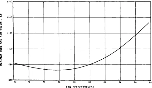
Weight vs Fin Effectiveness. The effect of area? or fin effectiveness, on radiator weight is shown in Fig. 7. It is seen that the weight of the tube and fins vs fin effectiveness goes through a broad minimum in the range of about 0.68 to 0.84. Although the actual point of minimum weight is around a fin effectiveness of 0.75, it is seen that there is a penalty of only 20 lb to increase the fin effectiveness up to 0.83 and thus reduce the required area by about 10$. Since there is an unknown but surely significant cost in additional package length, the fin effectiveness chosen generally will be in the neighborhood of 0.80 or higher.
Weight vs tube length. Figure 8 shows the effect of tube length, or number of vapor manifolds, on radiator weight.
The tube length is equal to radiator length divided by the number of vapor manifolds. It is seen that the weight of the fins and tubes decreases as tube length is decreased.
If the effect of manifolds were neglected, one might find that the optimum radiator had a great multiplicity of ex- tremely small tubes. However, when the weight of manifolds
is considered, the situation is markedly different. It is seen that the optimum weight occurs with a tube length of approximately 1/3 to 1/4 the radiator length, that is, with three to four sets of manifolds.
In the 350-kw Spur system, three sets of manifolds corre- spond to about 1100 tubes. If four sets of manifolds are used, the total number of tubes goes up from 1100 to about 1500. The increased difficulty of fabrication associated with using a larger number of tubes also favors no more than three manifolds. The reference design for the Spur system has three condensing sections with three sets of vapor and liquid manifolds.
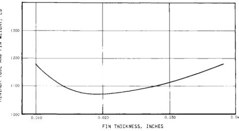
Weight vs fin thickness. If, instead of setting fin ef- fectiveness and varying numbers of tubes and fin thicknesses to determine the minimum weight for that particular value of fin effectiveness, one fixes a value of fin thickness and
then varies number of tubes and fin effectiveness to determine minimum weight, one can generate a curve such as shown in Fig. 9. This curve is particularly useful to the radiator designer because it shows that, although the minimum weight occurs at a fin thickness of only 0.018 in., for example, one can use a fin thickness as much as 50$
greater with only a small weight penalty.
Since the thickness of the fin is an important design variable that seriously affects the practicality of the entire radiator, this curve is very important to the de- signer. Based on the curve in Fig. 8, along with the re- sults of a preliminary stress analysis, and a qualitative assessment of fabricabi1ity of the radiator vs fin thick- ness, it was decided to use a fin thickness of 0.026 in.
for the Spur reference design.
Weight vs meteoroid parameters. The effect of meteoroid parameters on radiator tube and fin weight is shown in Fig.
Ю . The weights shown are optimized for the two material combinations shown as well as for the indirect (liquid- filled) radiators; they are plotted against the meteoroid modulus described previously.
Table 3 lists the values for K in the meteoroid modulus for eight different combinations of penetration theory, flux-mass relationship, and meteoroid density. The weight can be obtained for any other combination by using the proper value of K. The slope of the weight curves goes from 0 for low values of the modulus to 1 for high values. This is be- cause at the low end of the curve no additional armor is re- quired beyond that necessary for heat transfer, fluid flow, and fluid containment, whereas for the extremely severe meteoroid parameters, the weight, almost entirely armor,
is directly proportional to armor thickness needed.
Thus, although the meteoroid modulus, or relative thickness, varies by a factor of 20 in the range from the optimistic set of meteoroid parameters to the pessimistic set described earlier, the optimized tube-and-fin weight corresponding to these sets varies only between 2 and 7-1/2 lb/kwe. Reasons for this are that 1) at the low values, the armor required is less than that required for heat transfer and f 1 u idflow, and 2) the vulnerable area can be reduced as the meteoroid modulus
increases. With the manifold and structural requirements con- sidered, along with use of stainless steel-copper for the se- vere meteoroid parameters, the total radiator weight can vary
T a b l e 3 Values f o r K in t h e m e t e o r o i d modulus
Stainless- t rat Ion
eory * 12 12 12 12
Ю Ю Ю
10
DIstrlbut ion Whlpple, 1958 Whlpple, 1958 Eq. (3) Eq. (3) Whlpple, 1958 Whipple, 1958 Eq- (3) Eq. (3)
6 6
6 6
Density, g/cm3
0.4 2.7 0.4 2.7 0.4 2.7 0.4 2.7
b g h e f c d a b
Columb i um, K = 8.9 16.4 2.2 4. 1 24.0 45.5 6.1 11.4
copp<
K = 9.0 17.0 2.3 4.3 22.7 42.9 5.7 10.8 12 = BJork; Ю = Summers/Charters. л 0 3 Letters are Fig. 10 points; Modulus = o 7 [ l - P(0)]j>~ ' ; thin target factor of 1.5 used; for factor of 2,
multiply K by 2.0/1.5.
Direct vs indirect radiators. Comparison was made between direct radiators, in which the latent heat from condensation
is radiated directly to space, and indirect radiators, in which a separate liquid loop transfers the heat from a rela- tively small intermediate condenser to the radiator. The reason for interest in the indirect system is that the prob- lems of start-up and two-phase fluid management are simpler than in the direct system. The disadvantages are the require- ments for an additional liquid loop and for 25$ more area, be- cause the fluid temperature drops. The weight comparison is shown in Fig. 10. It is seen that, over the entire range of meteoroid parameters, the indirect radiator tube-and-fin weight is about the same as for the direct radiator. This curve does not, however, include the weight of the additional heat exchanger, pump, or piping required for the indirect system. Since the indirect system is heavier than the direct system by the weight of these components, and since it re- quires about 25$ more area, the direct radiator was chosen for the Spur reference design.
5. Material and Fabrication Considerations Choice of Material
The choice of material for the Spur radiator relates closely to the choice of structural container meterial for the system.
Thus, the reasons for selecting Cb-l$Zr for the reactor loop and the Spur power conversion loop are reviewed below.
The overall Spur objectives of 1 to 3 yr operation in space, 10 lb/kwe unshielded weight, and 2 ft2 of radiator per kwe re- quire temperatures at the reactor, boiler, and turbine in the 2000°F range. As none of the conventional metals, e.g., Fe, Ni, or Co base alloys, have adequate strength at this tempera- ture, refractory alloys must be used. Of refractories avail- able, only the columbium alloys have the required combination of fabricabi1ity and high strength-to-weight ratio. Of avail- able columbium alloys, Cb-lfoZr was chosen because of the amount of experience available with this alloy, and because it was known to have adequate strength, liquid-metal corrosion resis- tance, and weldability.
The reference radiator design, based on use of Cb-lfoZr, weighs 5 lb/kwe. The alternate material is a combination of stainless steel tubes and stainless steel-clad copper fins, with a radiator specific weight of 4-1/2 lb/kwe.
Both columbium and stainless steel have proved compatible with alkali metal fluids at the Spur radiator operating con-
ditions. The principal reason for comparing the two materials is that the use of a bimetal system, e.g., stainless steel with Cb, further complicates the system, although not severely.
If heavy meteoroid armament is required, the stainless steel- copper radiator would be used. (See Fig. 10 for a comparison of the weight.)
The three problem areas resulting from combining stainless steel with columbium are back transport of contaminants from the stainless steel to the columbium, mass transfer from the hot parts of the stainless steel section to the colder sec- tions, and bimetal joining.
Back transport of nitrogen and carbon would occur because Cb has a greater affinity for N and C than stainless steel.
Loop testing has confirmed that migration will occur and that columbium carbides and nitrides will be formed on the surface of the columbium, reducing both the ductility and corrosion resistance of the columbium. It is believed that, with close control of the N and C levels in the stainless steel, the ef- fect can be confined to the surface and thus be negligible.
The effect can be reduced further by using sacrificial foil in the potassium to remove the contaminants.
Mass transfer occurs because of a very slight solubility of the structural material in the alkali metal working fluid.
As the solubility level is highest at the hottest section, in
has shown that no significant mass transfer will occur in an al1-columbium system. The use of a stainless steel radi- ator at 1300° to 1400°F may cause some transfer of nickel.
Specific testing will be required to determine the amount.
If the mass transfer rate is significant, either a cold trap or a separate cooling loop may be indicated.
The bimetal joints that would connect the stainless steel to the columbium do not appear to be a severe problem area.
A special technique for making a hermetic joint has been de- veloped and evaluated. Stainless steels are known to have
low stress rupture weld efficiencies (approximately 50$> at 1300° to 1400°F). With low radiator fluid pressures, how- ever, this is not an important limitation.
Beryllium has been analyzed as a material for both meteoroid armament and for heat-conducting fins. Although insufficient
information is available to evaluate the relative merits of different armament materials, it recently has been indicated that strength as well as modulus of elasticity and density determine the relative weight of armament required. Since the strength of Be and the modulus of elasticity at 1300° to
1400°F are reduced greatly from its low-temperature values, it may not be an effective armament material, even on a theo- retical basis. Moreover, the history of bimetal fabrication of complex welded structures, where important differences in the coefficients of thermal expansion exist, is discouraging.
This has been especially true when one of the materials has limited fabricabi1ity, as with Be.
Fabricat ion
The general approach to fabrication of the radiator is to manufacture panels of reasonable size, perhaps 50 to 100 ft2 and, with simple mechanical and welded joints, assemble them
into the final radiator. For the refractory alloy radiator, the operations on each panel require a control 1ed-atmosphere welding chamber and a combination high-temperature brazing and annealing furnace. Assembly of the panels into a complete radiator is done with mechanical joints except for the fluid inlet and outlet lines to each panel. These lines are welded with "field" welding and annealing chambers.
Cb-l$>Zr alloy, which has excellent fabr icabi 1 i ty, has been produced in all significant mill forms from large forgings to smal1-diameter tubing. Two exceptions to its excellent welda- bility are as follows:
1) During welding, or at any other time that the material is above 400°F, it must be protected very carefully against contamination from oxygen, nitrogen, and hydrogen.
2) All welds must be annealed at 2200°F for 1 hr. Failure to anneal will allow even low-oxygen contents to reduce the corrosion resistance, increase the primary creep rate, and
increase embritt1ement.
Good welding practice for Cb-lfoZr requires that all welds be made in a chamber. Although it is recognized that many high-quality welds have been made in columbium alloys in open air with inert gas shielding, especially with simple joints, the procedure is not recommended for this type of assembly.
In view of the required reliability of the radiator and the cost of the components, the risk of out-of-box welds is not justified. The weld chamber must be capable of evacuation to a pressure of 5 x Ю "5 mm Hg. The recommended procedure
is to evacuate and purge three times with high-purity argon to attain a safe impurity level of 25 lb/min oxygen content.
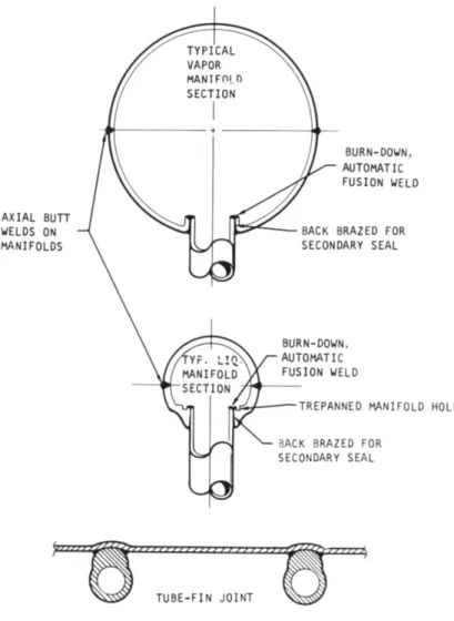
Since approximately 2000 tube-to-manifold joints are re- quired in the radiator, and failure of any one joint would cause system failure, it is a major concern of the program that joints of highest reliability be obtained. The only joint of this kind proved for liquid metal use with sta- tistically significant information is the welded and back- brazed type. Long-duration testing in liquid metal heat exchangers of both the air-to-liquid and liquid-to-liquid type has proved this joint sound and durable. Figure 11 shows two configurations that can be used. Joints that are welded only contain either stress concentrations at the root of the weld or irregularities at the base of the tube which could lead to local plastic strain and failure during temperature cycling. Also, it is felt that the high level of reliability required can be achieved only by an automatic tube-header weld. Automated joint welding can be attained easily when the manifold is made in two halves and with internal welding as shown in Fig. 11.
Although much work remains in developing brazing alloys and procedures for columbium alloys, no basic problems are apparent. A number of titanium and zirconium base alloys with melting temperatures between 1800° and 2350°F are being developed at Oak Ridge National Laboratory1 7 to be used at 1500° to 1800°F. The Spur program includes develop-
show that alloy additions of 5 to 10$ Fe, Ni, Co, and Zr provide suitable reductions in the melting points and that the resultant alloys have excellent wetability. It is ex- pected that greater ductility will be attained with these solid solution alloys than could be attained with eutectic mixtures.
6. Conclusions
Aside from heat transfer design and optimization of the radiator tubes and fins, the Spur radiator design study in- volved considerations of materials compatibility, fabrica- tion, structure, manifolding, radiation scattering, and two-phase fluid management.
The study resulted in a conical-cylindrical, tube-fin radi- ator fabricated of a columbium alloy. The study indicated a size, including subcooler, of 2 ft2/kwe and a weight of 5 lb/kwe. The most important design variable is the amount of armament required for fluid-passage meteoroid protection.
Although this could cause considerable weight variation (from 3-1/2 to 9 lb/kwe), it is not expected to have an appreciable effect on other design aspects. The study also showed that, for the power category of 300 to 1000 kwe, radiator deployment after launching would not be required.
Also, it is unlikely that segmentation, redundancy, or exotic combinations of materials or condigurations would be necessary.
References
1 Hawkins, G. S. and Upton, E. K. L., "The influx rate of meteors in the earth1s atmosphere," Astrophys. J. 128;
727-735 (1958).
2 Hawkins, G. S., personal communication to K. 0. Parker, Smithsonian Astrophysical and Harvard College Observatories (May 1962) .
3 McCrosky, R. E. and Soberman, R. K., "Results of an artificial iron meteoroid at 10 km/sec," Smithsonian Contrib.
Astrophys. (1962).
4 Cook, A. F., Jacchia, L. G., and McCrosky, R. E.,
"Luminous efficiency of iron and stone asteroidal meteors,"
Smithsonian Contrib. Astrophys. (1962).
5 Cook, A. F., personal communication to K. 0. Parker, Smithsonian Astrophysical and Harvard College Observatories (May 1962).
6 Whipple, F. L., "The meteoric risk to space vehicles/' Vistas in Astronautics (Pergamon Press, New York, 1958), pp. 115-122*.
7 Watson, F. G., Between the Planets, (Harvard University Press, Cambridge, Mass., 1956).
8 Duberg, J. E., "The meteoritic hazard of the environment of a satellite," NASA TN D-1248, p. 31 (1962).
9 Hawkins, G. S., "Radar determination of meteor orbits,"
Research Rept. 13, Harvard College Radio Meteor Project (1962).
0 Summers, J. L. and Charters, A. C , "High-speed impact of metal projectiles in targets of various materials," Proceed-
ings of the 3d Symposium on Hypervelocity Impact (Armour Research Foundation, Chicago, 111., 1959).
11 Eichelberger, R. J. and Gehring, J. W., "Effects of meteoroid impacts on space vehicles," ARS J. 32^, 1583-1591 (1962).
2 Bjork, R. L., "SNAP-sponsored meteorite penetration conference," Washington, D.C. (December 1959).
13 Wright, R. M., Johnson, A. L., Anderson, A. F., and Stake, R. T., "Thermal radiators for space vehicle environ- mental control systems," AiResearch Rept. STC-20-R (July 1962).
14 Stone, R. A., Shudde, R. H., and Friedman, H. L., "CROCK and SHOCK: fortran codes for optimization of heat-rejection systems for space power plants," NAA-SR-6727 (November 1961).
15 Coombs, M. G., Stone, R. A., and Kapus, T., "The SNAP 2 radiative condenser analysis," NAA-SR-5317 (July 1960).
16 Lockhart, R. W. and Martinelli, R. C , "Proposed corre- lation of data for isothermal two-phase, two-component flow in pipes," Chem. Eng. Progr. 45, 39-48 (1949).
7 Fox, C. W. and Gilliland, R. G., "Progress report on the brazing of columbium," ORNL 61-7-24 (July 1961).
VAPOR-LIQUID SEPARATOR REACTOR I
^UE
LOOP Г BOILER
TURBINE PRECOOLER
LOAD
ttttf,
7TT
uí nracïo
RECUPERATOR CONDENSER
__»» /RAD1AT0R ^
дшии GENERATOR|
ISUBCOOLER
UBCOOLER CONDENSER RADIATOR
Fig. 1 Spur flow schematic
LIQUID MANIFOLD
LIQUID MANIFOLD
Fig. 2 Reference design for a 350-kwe Spur system
FROM REACTOR
ZJ\ TO TURBINE
TOTAL WEIGHT
^-—*-^^_
POWER PENALTY
— ^ ^ su
P E N A L T Y ^ / ^ >
3C00LER WEIGHT PEN, \LTY
400 600 800 1000
GENERATOR COOLANT TEMPERATURE, °F
Fig. 4 Subcooler-generator weight trade-off
1300
400 300
\
\ \
£-
CONICAL/
\ TOTAL
9
SYSTEMNOTES:
REACTOR PACKAGE:
24" x 2 4 " CYLINDER ' SHIELD: 2 6 " THICK
o = 5 0 l b / f t3
RADIATOR COMPLETELY SHADOWED 9 . 5 FT PACKAGE DI/ WETER
1 1
^ T H R E E - F I N
.TOTAL
cnNF ^ ^
\ EAR
SYSTEM 1
^vvJ
Fig. 5
RADIATOR LENGTH. FT
V a r i a t i o n o f shield weight w i t h radiator length
10*
10°
1 0 - *
1 0 " *
io-6
10 ° o-io
o"u
n"l*i
[ o O AEROBEE (NO. 25) Г \ D AEROBEE (NO. 80) 1 \ O AEROBEE [ \ Д EXPLORER V I I I h \ O b, EXPLORER I 1 \ D D VANGUARD I I I [ V Q SPUTNIK I I I r- X ° N £ O PIONEER I
X а Ч A l COSMIC
\ \ Y ф 2 COSMIC Х^ Л \ \ PHOTOGRAPHIC RANGE-i
X \ X R A D A R RANGE-, /
x ^ x / / x J^^\ / 1
WHIPPLE, — ^ C ^ \ X / / 1958 (6) \ A \ /
/ \ ^ \ / \ /
EQUATION ( 3 ) - / \ / \ \J
M Kl
WATSON, 1956 {!)-/ \ Í S / _ , 1 L. 1 . 1 . 1 , 1 . 1 ^ O l
MASS, GRAMS
Fig. 6 Meteoroid f l u x vs mass
) 120
1100
1080
1060
70 72 74 76 78 80 82
FIN EFFECTIVENESS
Fig. 7 Minimum weight vs fin effectiveness
N = 700 TUBE AND SHELL WEIGHT-
N = 1500 NOTES:
ДР AND FIN EFFECTIVENESS OPTIMIZED AP IN VAPOR MANIFOLD = 1/4 PSI 9.5 PACKAGE DIAMETER
N = OPTIMUM NUMBER OF TUBES ALL Cb SYSTEM
Fig.
NUMBER OF VAPOR MANIFOLDS
8 Weight vs number of vapor manifolds
IMUM TUBE AND FIN WEIGHT, LB o o o o o o 2:
_^-—-"^
0.020 0.030
FIN THICKNESS, INCHES
Fig. 9 Minimum weight vs fin thickness
CONICAL RADIATOR 10 FT PACKAGE DIAMETER 3 VAPOR MANIFOLDS
ÜJ
Z Li_
1 LU CO ID H- 21 21
1000 900 800 700 600 500
400
300
k
C0NDENSER-RA
L. p
\-
L k
1 1 1 1
DIATOR-^.
e
_J..„1 LJ
\ ^ ^ ^ * a f \ \ .
s ^ ^ ^ a
C0LU
9
" ^ 9
\
^> ^ h
b st
> ^ h
M B I U M - ^ ^
r v
^ c 1 / d
d
\ V
y ^ STAINLESS STEEL*
<2Г АК'Г> r n D D C D
<5 А Г
4
^4-LIQUID-FILLED RADIAT0
1 1
*
1 1 1 1
0.3
AXIAL BUTT WELDS ON MANIFOLDS
BURN-DOWN, AUTOMATIC FUSION WELD
BACK BRAZED FOR SECONDARY SEAL
BURN-DOWN, AUTOMATIC FUSION WELD
TREPANNED MANIFOLD HOLE BACK BRAZED FOR
SECONDARY SEAL
Fig. 11 Examples of tube-manifold and tube-fin joints