Cite this article as: Kassai, M. "Recovering Heat from Condenser Unit Produced Refrigerant System in Food Processing Facility", Periodica Polytechnica Mechanical Engineering, 2019. https://doi.org/10.3311/PPme.14044
Recovering Heat from Condenser Unit Produced Refrigerant System in Food Processing Facility
Miklós Kassai1*
1 Department of Building Service Engineering and Process Engineering, Faculty of Mechanical Engineering, Budapest University of Technology and Economics, H-1111 Budapest, Műegyetem rkp. 3., Hungary
* Corresponding author, e-mail: kas.miklos@gmail.com
Received: 20 March 2019, Accepted: 09 April 2019, Published online: 20 May 2019
Abstract
The object of this research was to investigate of the energy performance of a national chicken slaughterhouse in order to achieve condenser heat utilization generated by the operation of the existing, refrigerant systems. The paper focuses also for the technical realization of condenser heat utilization by concept plans and payback time calculations. The utilizing heat of a cooling circle's condenser is a quite quickly returnable investment. The time of payback is around 330 days by heat utilizing for hot water preheating and also air heating.
Keywords
heat recovery, condenser heat utilization, refrigerant system, energy design, energy consumption, energy saving
1 Introduction
It’s essential how we treat the cut-off livestock from the aspect of breeding infections. There are several kinds of contaminations, microorganisms on the surface of a car- cass, or it’s likely that they settle down from the ambience.
They can be bacterias, viruses, mushrooms or mould. First as a microorganism occurs on the surface, it does breed slightly, or even doesn’t breed. In this stage the microor- ganism must adapt itself to the new ambience. After it, if successful, comes the exponential growth period during which the population of microorganisms can double two or more times every hour under favourable conditions. As the number of the microorganisms multiplied, the deple- tion of nutrients and the accumulation of toxins slow down the growth and start the death period. The rate they settle down depends on the quality of the meat and the environ- ment. Since it’s not possible to change the parameters of meat, or we don’t really want to change, only the proper- ties of the environment is what we can manipulate with [1-7]. The properties of air, as temperature, humidity, air flow velocity, and oxygen concentration. According to these variable parameters, we can pasteurize, chill down, humidify, dehumidify, ventilate, or change oxygen level, from the side of applied HVAC technology [8-12].
The investigated facility in this research is a slaugh- terhouse, established specifically to process poultry.
The rate of process is about 3000 poultries each hour.
During the procedure high cooling and heating energy demand occurs. Viktor Zicho MSc. student [13] has been a huge help in the realization of the project with his assist work and effort. To perform the energy calculations and evaluate the results, Microsoft Excel 2010 software was used in this research. As the livestock arrives at the facil- ity, the following treatment steps are applied:
1. Livestock cleaning with pipe-water 2. Veterinary examination
3. Stunning 4. Killing, bleeding
5. Scalding: during this step, the entire feathering is removed. This removal is facilitated by hot water, which is injected on the body of poultries. Thus feath- ers loosen up, which makes scalding more effective.
The injected hot water’s temperature is 65°C and the mass flow rate is 1kg/h.
6. Water bath 7. Feet removal 8. Gutting
9. Pre-chiller, cold-air blast: this step is also called shocking, since the carcasses temperature is decreased very quickly, herewith making the adaptation of microorganisms more difficult. The
temperature of chickens is 43 °C as they enter the chilling rooms. The aim is to decrease the tempera- ture of the poultry to the level of 3 °C in each point of the carcass.
2 Heat-and moisture load calculations of the conditioned spaces
Heat- and moisture load of the examined building is quite complex: transmission heat flow, heat flow of technol- ogy, human moisture- and heat load, evaporating water surfaces and lighting compose it. The slaughterhouse is located at Hajdúböszörmény, Hungary. The design exter- nal temperature is Te = -15 °C, the average soil tempera- ture during heating season is Tm,e = 4 °C.
The heated (or likely heated) space: 1566 m2. Expediently we should divide the building to zones with different temperatures, according to the assigned room’s function. Each zone is set out in Table 1.
According to standard No. EN12831 the heat loss of each room can be computed from six components: trans- mission heat loss, heat radiation of warm surfaces, heat load of evaporating water surfaces, heat load of people, machines and lighting (Eq. (1)).
Q Q= tr+Qhs+Qew+Qp+Qm+Ql (1) Since this method is a routine algorithm in building technology profession, we won’t negotiate it thoroughly.
Conclusions and upshots are unfolded in the next chapter.
Among the rooms, the scalding room and its ambience might have the highest heat load. We considered it import- ant to examine this area of building from the aspect of heat load. The 3000 chickens transiting every hour and the sprayed 1 l hot water per chicken means high amount of generated steam. In addition, a scalding machine is also in service, which generates about 3 kW heat flow.
Value of steam were calculated by Eq. (2).
Qew= ⋅m hS = ⋅ ⋅A β
(
pSs−pS ti| ,ϕ)
⋅(
cp S, ⋅t rv+ 0)
(2) One poultry stays about twenty minutes in the room, consequently water evaporates from about 1000 chicken body coincidentally. Thus evaporation surface can be esti- mated with 1000 sphere’s surface (Eq. (3)).A=1000 4⋅ r2π =3000 4 0 07816⋅ ⋅
(
.)
2⋅π =76 7. m2 (3) Mass flow rate of evaporation aware of air velocity (1 m/s) among hanged meat pieces (Eq. (4)).β =
(
+ ⋅)
⋅ =(
+ ⋅)
⋅= ⋅
− −
−
4 581 3 39 10 4 581 3 39 1 10 7 971 10
8 8
8
. . . .
.
vair kg sNN
(4) Pressure of saturated water at 25 and 65 °C: 3170 Pa, 25041 Pa. Maximal relative humidity is 85 %. Partial steam pressure in the room (Eq. (5)).
pS ti| ,ϕ = pSs ti, ⋅ =ϕi 3170 Pa* .0 85=2695 Pa (5) Moisture load from generated steam (Eq. (6)-(8)).
mew= ⋅ ⋅A β
(
pSs−pS ti| ,ϕ)
(6)
mew=76 7 7 971 10. ⋅ , ⋅ −8⋅
(
25041 2695−)
(7)mew=0 1366. kg s (8)
Heat load from generated steam (Eq. (9)-(10)).
Qew= ⋅ ⋅
(
−)
⋅ ⋅ +
− ⋅
76 7 7 971 10. . 8 25041 2695 1 86 65 2500. kJ kg (9)
Qew=358 1. kW (10)
Besides this, the heat load given by the scalding machine (3 kW) and the lighting (0.7784 kW) is not significant.
Processes performed in this room are entirely automated, there is no staff working here constantly. The scalding room loses 3.51 kW heat flow through the walls. Summarizing these values, total heat load in the scalding room is 358.3 kW, which is leaded off by a ventilation system. The upshot is a value far over my expectations, actually it is greater than the heat flow ejected from the shocker’s condenser.
This means, there are two possible concepts for heat supply from wasteheat: with condenser heat recovery, negotiated before, or recovering energy from the ejected air diverted from the scalding room. Considering these opportunities, we analyse two constructions in the following.
Table 1 Design temperature room-by-room
Room Design indoor
temperature (°C) Scalding room and its ambience 25
Residential areas 20
Work zone 16
Store, garage, etc. 12
Refrigerator store 0
Freezer, fore-cooler -20
Shock freezer room -35
Performing the computation in case of each heated room, heat demand of the building is∑ =Q 41 65. kW regarding winter design circumstances. This outgoing heat flow must be in equilibrium with the performance provided by the heat supply system.
In winter design conditions there is a great performance need, in order to warm up the external air to the requested temperature. W calculated the mass flow rate of inlet air for the existing four temperature-zones (Eq. (11)).
m Q
c T
Q c T T
air zone
air temp differential
zone
air in out
= =
(
−⋅∆ .� ⋅
))
(11)Performance of air heaters depend on the specific temperature differential and the mass flow rate coming through them (Eq. (12)).
Qair heater� =cair⋅mair⋅ ∆Tair heater� (12) External air is let in the scalding room without any treat- ment and heating. The other rooms get air supply from a common air duct, then it forks into two ducts: Air heater No. 1 heats up to 15 °C, No.2 to 19 °C appropriately for zones 12 °C and 16 °C, since temperature differential is 6 °C between ventilated and exhaust air in each room.
After air heater No. 2 air can flow directly to zone 16 °C or it air handler of zone 20 °C. The latter is equipped with an adiabatic air moisturizer and a post-heater. The calcu- lated heating energy demand of the air heaters can be seen in Table 2.
After air heater air of zone 20 °C flows through the adiabatic moisturizer, where moisture gains up to 95 % relative humidity, its temperature drops to 7 °C. Task of post-heater is to heat it up to 23 °C. Considering it, per- formance of air heater No. 3 can be calculated by Eq. (13).
Qair heater No. 3=mzone 20 °C⋅ ∆c T⋅ (13)
The calculated mass flow rates for air heaters can be seen in Table 3.
3 Development of heating energy utilization system Let it be a standard or any kind of heat recovery equipped system, the three air heater must provide these above sum- marized performances. Thus total heat flow is 303 kW.
Regarding this value, the condenser heat flow can’t cover the building’s demands entirely. However, this system or scalding room heat recovery can function perfectly, because design heat losses occur only few days long a year. Thus air heaters must provide the maximal perfor- mance only rarely.
Investment costs might let us decide between the two available systems. One thing is already known: from heat recovery constructions it is preferable to use construction B), because air heating has a great demand, exceeding the 210 kW supplied limit. As written before, the optional con- cepts are condenser heat recovery, utilized coincidentally for air heating and DHW preheating, or scalding room heat recovery with cross flow plate-type heat recovery appliances, combined with condenser heat recovery uti- lized for DHW preheating. Let us denominate the former as construction A) and the latter as construction B). These formations should be compared from aspect of energetics and economy, too. This comparison is performed in the following chapter. Let us assume that formation without any kind of heat recovery is the standard construction.
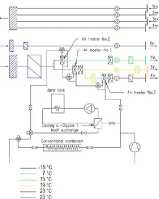
On the following pages, construction A) and then B) is demonstrated (Figs. 1-2). Signs of rooms are on the right side of figures:
1. Scalding room 2. Zone 12 °C 3. Zone 16 °C 4. Zone 20 °C
In case of construction A) there are three branches tied up paralelly substituting the conventional condenser. All three branches can be disconnected with ball valves on the two sides. At the end of branches, they unite with auto- mated diverter valves. There is an option to disconnect the air heaters also, with diverter valves. There are also conventional air heaters installed after the heat recovery ones, for the case of heat recovery malfunction or for tem- pering heating and post-heating. They are supplied by a condensing boiler. These air heaters are illustrated with
Table 2 HVAC technology data of zones and heat performance of air heaters
Zone Heat
demand of zone (kW)
Air mass flow rate (kg/s)
Volumetric flow rate
(m3/s)
Heat performance of air heater (kW)
20°C 25.72 4.287 3.133
223.8
16°C 13.77 2.295 1.678
12°C 2.16 0.360 0.263 10.8
Table 3 Mass flow rate and performance of air heaters Air heater Mass flow rate through
air heater (kg/s) Air heater performance (kW)
1 0.36 10.8
2 6.582 223.8
3 4.287 68.6
dashed lines. The DHW preheater is connected with an NTH heat exchanger.
In case of construction B) the heating of rooms is solved with cross flow plate-type air-to-air heat recovery units.
The arrangement of heat exchangers is the same as in case A) from the ventilated air side. From the exhaust air side, they are connected in series with bypass branches for each.
In addition, an NTH heat exchanger is also installed on the cooling circle of shocker. On secondary side glycole tinc- ture flows, this lets through a spiral heat exchanger in the hot water tank. Here, in B) te only circle separated from the cooling circe is this latter. The conventional condenser is attached directly, because heat ejection is more effective on the temperature level 35 °C. If it was on an indirect cir- cle, the temperature would be lower and in summer condi- tions heat ejection would be worse.
On Figs. 1-2 the meaning of “in” is the injected fresh air into the conditioned spaces, while “ex” represents the exhaust air delivered form the given spaces.
3.1 Investigation of Construction A)
In case A) we can’t use the same air heaters as in standard case. Thanks to lower flow temperature and the caused smaller temperature differential, higher heat exchange sur- face is necessary. On the margin, the same heat exchanger can’t be used with refrigerant R134A and water coinciden- tally. It is also important to actuate a post-heater, because of
insufficient heat recovery performance. Incremental costs are compounded by the expenses of DHW preheater parts and construction, and costs of the three large-surfaced air heaters and their installation costs. Examining the DHW preheater’s installation, it consists of a 104.7 kW NTH heat exchanger’s a pump and a spiral heat exchanger capable to eject 104.7 kW heat flow to the inlet water in the water tank. Additionally, five automated diverter valves steepen the investment. Datas of air heaters were inserted in a heat exchanger designer program from Zeller Consulting Souisse, and then results given by program were used in the following. Installing the spyral coil heat exchanger in the preheater DHW tank can not be implemented, so we over- estimated the costs with a new two heater coil-equipped DHW tank. The Hungarian distributor of Alfa Laval sup- ported our research with price offer for the 104.7 kW NTH heat exchanger. Unfortunately, they could not provide this kind of heat exchanger, but a low flow resistance plate-type one was recommended instead of it. Its pressure drop is only 756 Pa, which is an acceptable value.
The investment costs:
• 1 Zeller 32.0/27.7/12.4- 1R- 46T- 1381A- 2.9PA- 11C- 17- 16 air heater, 548 €
Fig. 1. The schematic technical diagram of Construction A)
Fig. 2 The schematic technical diagram of Construction B)
• 1 Zeller 32.0/27.7/12.4- 1R- 46T- 1310A- 8.0PA- 22C- 88- 54 air heater, 752 €
• 1 Zeller 32.0/27.7/12.4- 1R- 46T- 1357A- 8.0PA- 11C- 41- 35 air heater, 545 €
• 1 Alfa-Laval AC-230EQ-210H plate-type heat exchanger, 3500 €
• 1 Grundfos CR45-1-1 pump, 988 €
• 1 Remeha HT 500 ERR water tank with two heat exchanger coils, 1159 €
• 5 diverter valves with valve engine and control sys- tem, 1587 €
• The installation works, which is 317 €.
Summarizing, the total investment cost is 9.396 €.
When installing a new energy system, it is essential to calculate the annual savings of primary energy sources.
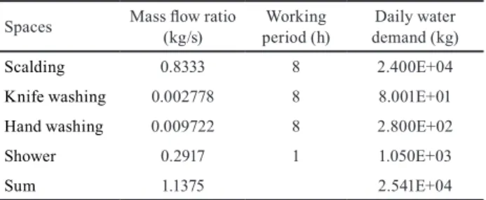
In case of condenser heat utilization DHW preheating has the higher priority, while heating is secondary. Warming up the DHW from 11 °C to 33 °C would be performed by gas-fired boilers, when heat recovery is not available. First it doesn’t seem to be a great amount of energy, but consid- ering water’s high heat capacity and high mass flow rate, it must be significant. In the last column of Tables 4-5 total daily heat demands must be distributed by 8 h, assuming that, shift in the slaughterhouse and working period of pre- heater is 8 h every day.
In terms of payback calculations, this average perfor- mance can be applied also for morning heating up, for 1.5 hours. Preheater starts coincidentally with the shock- er’s cooling cycle. It warms up water to the desired tem- perature, because heat loss occurs on the walls of the DHW tank, and water temperature sinks significantly at night.
Heating of the building works 9.5 hours a day, between stationary conditions. In the calculation of saving, we assumed the performance of morning heating up equal to normal stationary heating. In the half of annual heating period the condenser’s heat flow wouldn’t be able to cover this incremental performance, necessary for heating up.
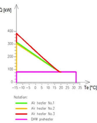
In the other half of heating period, this increment is neg- ligible. These steps in the calculation set back the return period. On the following figures (Figs. 3-6) we illustrate the heat demand in the function of external temperature.
Let heat demand of DHW preheater be constantly 81.13 kW, independently of external temperature. But per- formance of air heaters depends strongly on external tem- perature. All three air heaters reach their maximal perfor- mance in case of -15 °C, the design ambient temperature (Table 2.2), while No. 1 heats up to 15 °C, No. 2 up to 19 °C,
No. 3 up to 20 °C. Curves of air heaters No. 1 and 2 are linear, but in case of No. 3 it becomes a polinomial func- tion, since humidity of external air rises significantly with temperature. This behaviour influences air moisturizing
Table 4 Water demand of DHW preheating Spaces Mass flow ratio
(kg/s) Working
period (h) Daily water demand (kg)
Scalding 0.8333 8 2.400E+04
Knife washing 0.002778 8 8.001E+01
Hand washing 0.009722 8 2.800E+02
Shower 0.2917 1 1.050E+03
Sum 1.1375 2.541E+04
Table 5 Heat demand of DHW preheating Spaces Daily heat demand
(MJ) Average
performance (kW)
Scalding 206.95 76.63
Knife washing 7.36 0.26
Hand washing 25.75 0.89
Shower 96.57 3.35
Sum 336.63 81.13
Fig. 3 Performance of DHW preheater in the function of external temperature
Fig. 4 Performance of air heater No. 1 in the function of external temperature
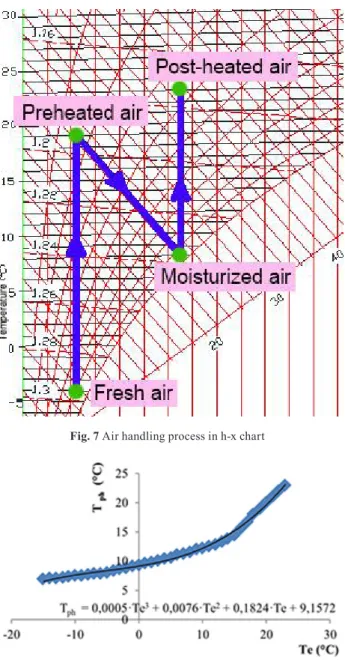
intensity and post-heating indirectly. It is quite easy to assign the inlet temperature in air heater No. 3 with fram- ing on h-x diagram (Fig. 7). This framing is illustrated in Fig. 2.6. on an example: we start from point -4 °C and 80 % relative humidity, and warm up the air in air heater No. 2 until 19 °C. After this, comes moisturizing via the adia- batic moisturizer to 95 % relative humidity. Temperature is easily readable in this point, it becomes 8.3 °C. From this point, the post-heater’s duty is to warm up the air again.
I performed this framing for all integer value tempera- tures from -15 °C to 19 °C. Since external temperature gets higher, humidity also rises and the sprayed water mass flow rate diminishes. As a consequence, inlet tem- perature in air heater No. 3 increases.
Post-heating initial temperatures (Tph) belonging to the appropriate external temperatures are listed in a table, and illustrated on a diagram (Fig. 8).
According to these datas we could frame the charac- teristic curve of air heater No. 3, thus aware of all three air heater’s and DHW preheater’s performance curve it is preferable to handle them together.
Each characteristic curve is fitted onto each other, thus summing up the performance values, we obtained the summarized heat demand diagram (Fig. 9).
Annual saving is computable only if we find relation between run period and performance. There is a curve, called frequency distribution of temperature, which helps finding the relation. This is a duration chart, which shows how often does external temperature stay under assigned temperature limits, according to long-term averages (Fig. 10).
We blocked in the condenser’s heat performance in the obtained performance-period curve, too. It is the available, consumable heat performance, a dim pink line illustrates it. As it is visible, in a short part of the heating period, the
Fig. 5 Performance of air heater No. 2 in the function of external temperature
Fig. 6 Performance of air heater No. 3 in the function of external temperature
Fig. 7 Air handling process in h-x chart
Fig. 8 Initial post-heating temperature in function of ambient air temperature
condenser can’t cover all the needs. There are also peri- ods, when a part of the heat is not utilized, the rest must be rejected to environment. The saved amount of heat is illus- trated with cross-hatch. The area covered by this, could be measured by AutoCAD’s surface measuring module. The total saved heat becomes 4.502TJ, but the shocker’s cool- ing cycle doesn’t work all day, only 9.5 and does it only on weekdays. Portion of working period (Eq. (14)):
9 5 5 52
8760 0 282
.
. h
day days week
weeks annum h
⋅ ⋅
= .
(14) Multiplied with this coefficient, the real saving is by Eq. (15):
Qsavings a, =0 282 4 502. ⋅ . =1 27. TJ. (15)
Divided with annual boiler efficiency, we get the heating value of saved fuel by Eq. (16):
Q Q
saving fuel a saving a , ,
, TJ
= = = TJ
η
1 27
0 75 1 693 .
. . . (16)
Finally, the saved expenses aware of natural gas price by Eq. (17):
C p Q
MJ
MJ
a a
= ⋅ fuel =0 00618. € ⋅1693000 =10463€ .
(17) Electricity consumed by the pump of DHW preheater cir- cle, which is an incremental operational cost by Eq. (18):
W pV
pump e
pump
, = ⋅ = ⋅ ⋅ kWh
τ = η
∆
2470 45600 0 01 0 79. 1426
. . (18)
According to the total electricity consumption of the slaughterhouse, it belongs to A1 pricing category, which distinguishes peak load and its opposite. The factory works in the supplyer assigned peak period, when price of electricity is 0.1379 €/kWh. Thus, pump operational cost is were calculated by Eq. (19).
C p W= ⋅ e =43 44. *1426 =196 6. a
kWh€ kWh € (19)
Thus altogether incremental energy costs of construc- tion A) is 196.6/a. Incremental investment costs were paid in one sum, without taking a loan. The easiest way to exemplify the return, might be a diagram. The costs of standard construction and A) construction were illus- trated in function of time. Let us assume, that zero point is standard construction’s investment cost. Consequently, incremental costs occur as absolute expenses. Standard construction’s operating costs are equal to the occurring expenditures without any heat recovery technology.
An idea presents itself, that heat recovery unit is installed during the building of the slaughterhouse, coinci- dentally with the installation of conventional air handlers.
In this case, the air heaters supplied from the conventional gas boiler have got only supplementary role. Considering it, the conventional air heaters would be designed to pro- vide total design heat flow only if redundancy was the concept at engineering. From now on, this construction is called A1). If heat recovery failure occurs and can’t sup- ply heat, the other conventional air heaters can cover all the demand. However, much more economical construc- tion is, when they are designed only to the rest heat per- formance, which is not covered by the heat recovery air heaters. In details, it means that smaller surfaced heat exchangers, smaller gas boiler and smaller diameter pipes
Fig. 9 Summarized heating energy demand diagram
Fig. 10 The performance-time duration curve
are necessary. From now on, this compound is called A2).
This causes a difference in thrift, compared with A1) its payback period is expected to be shorter. Zero point is the investment cost of standard case, additional cost is the heat recovery unit’s investment cost, and the difference between the two gas-supplied air heater system’s price must be educed (Fig. 11).
We obtained price offers for each air heater in case A1) and A2) from the Hungarian distributor of Rosenberg air handling unit producer. The data of conventional air heat- ers can be found in Table 6.
Rosenberg gave absolutely the same prices for air heat- ers independently from performance. Thus air heaters don’t play role in the differential costs between the two constructions. However, gas boilers make a very signifi- cant difference.
As heat source, we selected high performance gas boilers from Viessmann. In case of A1) the gas boiler is designed to the total heat demand, which means 384kW heat flow rate, desired from the gas boiler. According to it, we selected the 408kW nominal performance model from the high performance Vitodens boiler family. Gross price, which we obtained from the manufacturer, is 26 130. In case of A2) we selected the same kind of boiler, but a lower performance one with 187kW. Its gross price is 16 286.
During operation, nominal performance of both con- struction is equal to the A2) design performance, because conventional gas supplied heating of A1) operates on its design performance only if heat recovery unit breaks down and the external temperature is also at design tem- perature. Accordingly, boiler of A1) is going to work on
part-load. Fortunately, while it is a condensing furnace, the efficiency doesn’t change drastically with load reduc- tion. The pump is also at the same operating point. So there is no significant difference in operating between the two analysed constructions.
Finally the total difference is the bias between the two furnace’s price: 16 286. This price compared with the pipe price differences, this latter can be neglected. This means, that payback curve of A2) starts from that much below compared with curve of A1).
3.2 Investigation of Construction B) Summing up, the investment costs:
• 1 Zeller 10,7kW cross-flow plate type heat exchanger, 1627 €
• 1 Zeller 223kW cross-flow plate type heat exchanger, 1775 €
• 1 Zeller 68,6kW cross-flow plate type heat exchanger, 1627 €
• 1 Alfa-Laval AC-230EQ-210H plate type heat exchanger, 3500 €
• 1 Grundfos CR45-1-1 pump, 988 €
• 1 Remeha HT 500 ERR water tank with two heat exchanger coils, 1159 €
• The installation works, which is 317 €.
By this way the total investment cost is 11.454 €.
The scalding room operates all the time, when meat process is running. Thanks to the high heat load inside it, the exhaust 25 °C and 25 kg/s air ensures the heating of building between every condition. However, there is no heating before the operational hours of the slaughterhouse, which means preheating is not solved with this heat recov- ery construction. As a consequence, conventional air heat- ers must ensure it.
Thus, heat exchangers operate 8 hours daily, their per- formance in function of external temperature is the same as in case of A). Since the same frequency distribution curve is used, the framing applied in Fig. 12 results almost the same, with one difference: it doesn’t contain DHW preheating – this role is played by the condenser heat uti- lizer. The air-to-air heat recovery units cover the entire heating demand. In case of normal operation, the conven- tional gas-supplied heaters are not used.
The heating energy saved is the area under the curve, which must be multiplied with the appropriate utilization ratio. As described above, the air heaters operate 8 hours daily. Based on it, the ratio was calculated by Eq. (20):
Table 6 Investment costs of air heating coils
Air heater # A1) A2)
1. 122 122
2. 338 338
3. 235 235
Fig. 11 The payback period of Construction A)
8 5 52
8760 0 2374
h day
days week
weeks annum h
⋅ ⋅
= . . (20)
Heat amount measured with AutoCAD area measuring tool is 2.254TJ, while the real saving was calculated by Eq. (21).
Qsaving annual heating, , =0 2374 2 254. ⋅ . =535GJ (21) The performance of the condenser heat utilizer DHW pre- heater is also covered entirely during the daily 9.5 hours operating period. Thus annual saved heat was calculated by Eqs. (22)-(23):
Qsaving annual DHW, , =Qdaily average⋅τ (22)
Qsaving annual DHW, , W s h
h day
days week
=81130 ⋅3600 ⋅9 5. ⋅5 ⋅52weekks a GJ
=721 .
(23) Total annual saved heat amount is their sum was calcu- lated by Eqs. (24)-(25).
Qsaving annual, =Qsaving annual heating, , +Qsaving annual, , DDHW (24) Qsaving annual, =535GJ+721GJ =1256GJ =1 256. TJ
(25)
Divided by the annual boiler efficiency, we obtain the saved fuel’s energy content (Eq. (26)).
Q Q
saving fuel annual saving annual TJ
, ,
= , =
η 1 675. (26)
Finally, the saved costs aware of natural gas price (Eq. (27)).
C p Q
GJ
GJ
fuel a
= ⋅ =6 181. € ⋅1972 =10352 € a (27)
Pump operation cost of the DHW preheating circle is 196.6/a, the same value as in case A). Incremental investment
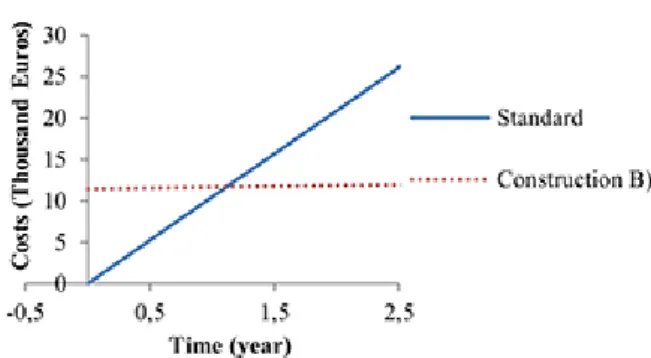
costs were paid in one sum, without taking a loan. The easiest way to exemplify the return, might be a diagram. On Fig. 13 the costs of standard construction and B) construction were illustrated in function of time. Let us assume, that zero point is standard construction’s investment cost. Consequently, incremental costs occur as absolute expenses. Standard con- struction’s operating costs are equal to the occurring expen- ditures without any heat recovery technology.
4 Results and conclusions
The utilizing heat of a cooling circle’s condenser is a quite quickly returnable investment. The time of payback is around 330 days in case of A) construction (condenser heat utilizing for hot water preheating and air heating), according to the corresponding diagram. This value is exceptionally good for a return period. Payback period of A2) became even bet- ter. It returns immediately, because setup of lower nominal performance gas-supplied air heaters means a greater sav- ing, then incremental costs of the heat recovery unit. In fact, price of construction A2) is lower than the price of standard case. If similar heat utilizers on other cooling circles of the slaughterhouse were installed, all the heating and hot water preheating demands would be covered throughout the year.
This kind of waste heat utilizer can be used in any type of facility, where heating and cooling demands occur coinci- dentally. Competitor might be the plate type air-to-air heat recovery unit. Here, in case B) (condenser heat utilizing for hot water preheating and applying heat recovery unit for air heating) the operational costs are the same as in case A1) and A2), however, the investment expenses are higher. As a con- clusion, the return time is also longer, it is around 350 days, according to the corresponding diagram. All three con- structions have their disadvantages: A1) and A2) is unable to cover all the heating and hot water preheating needs in a certain part of the year, while B) cannot cover it during the heating up period. Comparing the constructions, A2) might be the best choice, but it is feasible only if its installation is
Fig. 12 The energy savings in heating Fig. 13 The payback period of Construction B)
References
[1] Capozzoli, A., Grassi, D., Causone, F. "Estimation models of heat- ing energy consumption in schools for local authorities planning", Energy and Buildings, 105, pp. 302–313, 2015
https://doi.org/10.1016/j.enbuild.2015.07.024
[2] Ben Slama, R. "Water-heater coupled with the refrigerator to develop the heat of the condenser", In: International Renewable Energy Congress, Sousse, Tunisia, 2009, pp. 12–18.
[3] Reindl, D. T., Jekel, T. B. "Heat recovery in industrial refrigera- tion", ASHRAE Journal, 49, pp. 22–28, 2007.
[4] Cuce, P. M., Riffat, S. "A comprehensive review of heat recovery systems for building applications", Renewable and Sustainable Energy Reviews, 47, pp. 665–682, 2015.
https://doi.org/10.1016/j.rser.2015.03.087
[5] Nellis, S., Klein, S. "Heat Transfer", 1st ed., Cambridge University Press, Cambridge, UK, 2008.
https://doi.org/10.1017/CBO9780511841606
[6] Nyers, A., Pek, Z., Nyers, J. "Dynamical Behaviour of a Heat Pump Coaxial Evaporator Condensing the Phase Border’s Impact on Convergence", Facta Universitatis, Series: Mechanical Engineering, 16(2), pp. 249–259, 2018.
https://doi.org/10.22190/FUME180424019N
[7] Januševičius, K., Streckienė, G., Bielskus, J., Martinaitis, V.
"Validation of Unglazed Transpired Solar Collector Assisted Air Source Heat Pump Simulation Model", Energy Procedia, 95, pp. 167–174, 2016.
https://doi.org/10.1016/j.egypro.2016.09.039
[8] Ghazanfari, S. A., Wahid, M. A. "Heat Transfer Enhancement and Pressure Drop for Fin-and-Tube Compact Heat Exchangers with Delta Winglet-Type Vortex Generators", Facta Universitatis, Series: Mechanical Engineering, 16(2), pp. 233–247, 2018.
https://doi.org/10.22190/FUME180117024G
[9] Takács, J., Straková, Z., Rácz, L. "Costs Analysis of Circulation Pumps for Heating of Residential Building", Periodica Polytechnica Mechanical Engineering, 62(1), pp. 10–15, 2018.
https://doi.org/10.3311/PPme.10606
[10] Takács, J. "Possibility of Geothermal Water’s Using in Geothermal Energy Systems", Periodica Polytechnica Mechanical Engineering, 61(4), pp. 272–275, 2017.
https://doi.org/10.3311/PPme.10546
[11] Jedlikowski, A., Anisimov, S., Danielewicz, J., Karpuk, M., Pandelidis, D. "Frost formation and freeze protection with bypass for counter-flow recuperators", International Journal of Heat and Mass Transfer, 108(Part A), pp. 585–613, 2017.
https://doi.org/10.1016/j.ijheatmasstransfer.2016.12.047
[12] Anjomshoaa, Salmanzadeh, M. "Finding a criterion for the pressure loss of energy recovery exchangers in HVAC systems from thermodynamic and economic points of view", Energy and Buildings, 166, pp. 426–437, 2018.
https://doi.org/10.1016/j.enbuild.2018.02.016
[13] Zicho, V. "Hűtőkörfolyamat kondenzátorhő hasznosítása"
(Condenser heat utilization of refrigeration system), presented at Conference of Scientific Students’ Associations, Budapest University of Technology and Economics, Budapest, Hungary, Nov. 17, 2015. (in Hungarian)
in coincidence with the building of the facility. If it is not possible, A1) might be the favourable because of shorter pay- back period. At each investment or construction work, we must plan the operation of heat pumps very substantially, and beyond the cooling demands, we should always inves- tigate the coincidental heating demands. It’s also true for the opposite direction: if we apply the heat pump basically for heating or hot water preheating purpose, we should uti- lize the cooling performance of the evaporator, if there is such demand. Considering this approach, significant savings without any negative change on the cooling circle’s opera- tion can be achieved. The investment to recover heat from the investigated condenser unit has not been realized, but it is under consideration by the investors.
Acknowledgement
This research project was financially supported by the National Research, Development and Innovation Office from NRDI Fund [grant number: NKFIH PD_18 127907], the János Bolyai Research Scholarship of the Hungarian Academy of Sciences, and the ÚNKP-18-4 New National Excellence Program of the Ministry of Human Capacities, Budapest, Hungary. Moreover the research reported in this paper was supported by the Higher Education Excellence Program of the Ministry of Human Capacities in the frame of Biotechnology research area of Budapest University of Technology and Economics (BME FIKP-BIO).