SIXTH SYMPOSIUM ON BALLISTIC MISSILE AND AEROSPACE TECHNOLOGY
EVAPORATIVE FILM COOLING A T HYPERSONIC VELOCITIES FOR RE-ENTRY V E H I C L E S *
D r . Rudolf Hermann University of Minnesota
Institute of Technology
Rosemount Aeronautical Laboratories R o s e m o u n t , Minnesota
Abstract
A theoreticaj analysis of similarity parameters of e v a p - orative film cooling w a s developed for blunt bodies indicating the effect of m a s s transfer on heat transfer and skin friction for PrandtI and Lewis numbers unity. Calculated interface temperatures are in good agreement with wall temperatures measured around a hemisphere in a hypersonic wind tunnel. A p - plication of the analysis shows that evaporative film cooling
is feasible for typical re-entry v e h i c l e s . At circular v e l o c - ities the effective heat of evaporation of water is as high as 11,000 B t u / l bm. The significant advantage of evaporative film cooling is that the w a l l s of a vehicle during re-entry are maintained at relatively low temperatures.
Summary
Re-entry v e h i c l e s moving through the atmosphere at hy- personic velocities encounter considerable h e a t i n g , particu- larly in the stagnation point r e g i o n . V a r i o u s schemes for effective cooling have been investigated during the last few y e a r s , mostly in the category of m a s s transfer cooling. One of these schemes is transpiration cooling; another is cooling by ablation. Evaporative film cooling is another scheme of m a s s transfer cooling which h a s been investigated analytically and experimentally at hypersonic v e l o c i t i e s . In principle it consists of a one-spot injection of an evaporative liquid c o o -
lant (such as w a t e r ) near the stagnation point of a blunt b o d y , typical for fuselage or blunt leading edge of a re-entry v e h i - c l e . The coolant forms a very thin film (some lOOO'ths of an inch) due to high shear f o r c e s . Evaporation from the film is
* T h ? s research w a s supported by the United States Air Force O f f i c e of Scientific R e s e a r c h , Contract AF 4 9 ( 6 3 8 ) - 1 9 0 .
1 1 5
SIXTH SYMPOSIUM ON BALLISTIC MISSILE AND AEROSPACE TECHNOLOGY
self-controlled according to the local heat transfer condi
tions.
Experiments conducted In the hypersonic wind tunnel of the Rosemount Aeronautical Laboratories, University of Minne
sota, at Mach number 7 and stagnation temperatures up to 3000°R have demonstrated the feasibility of the method. A theoretical analysis of similarity parameters w a s developed for blunt bodies indicating the effect of mass transfer on heat transfer and skin friction for Prandtl number and Lewis number unity. Calculated interface temperatures are In good agreement with measured wall temperatures around a hemisphere.
Application of the analysis beyond the experimental range shows that evaporative film cooling is feasible for typ
ical re-entry vehicles such as a gliding vehicle or ICBM, and thermodynamic conditions at the interface are located between the triple point and critical point of water vapor. At circu
lar velocities the mass fraction of water vapor at the inter
face is high (about 0.9) and the heat blockage parameter is very low (about 0, 1 ) , which results in an "effective heat of evaporation" up to 11,000 B t u / l bm. The significant advantage of the evaporative film cooling is that the walls of the vehi
cle during the entire re-entry are maintained at a rather low temperature, about 550°R for a gliding vehicle and below 950°R for ICBM. Other advantages of the method are also discussed.
List of Symbols A reference area of vehicle
b width in two dimensional case; arc length from 0°-90°
CD drag coefficient, referred to area A C^ skin friction coefficient
C^ lift coefficient, referred to Area S 0 ^ specific heat at constant pressure D drag of vehicle
diffusion coefficient
Η total or stagnation enthalpy h enthalpy
Κ mass fraction of water vapor k thermal conductivity
L lift of vehicle Le Lewis number
L enthalpy of formation of vapor (including heating of Iiqui d)
Μ Mach number; molecular weight rfi mass flow
ρ pressure
114
SIXTH SYMPOSIUM ON BALLISTIC MISSILE AND AEROSPACE TECHNOLOGY
ρ pi tot pressure; stagnation pressure behind normal
p shock
Pr Prandtl number q local heat flux
Qef f effective heat of evaporation for water in film coo- Iing process
R radius of curvature
r heat of evaporation at temperature Τ Re Reynolds number
rQ radius of cross section of body of revolution S reference area of vehicle
s distance along gas-liquid interface, measured from stagnation point
SQ distance over which coolant is injected St Stanton number
Τ absolute temperature
u, ν components of velocity parallel and normal to gas-liq
uid interface ν velocity of vehicle χ length in flow direction y distance normal to interface α thermal diffusivity k/Cpp γ ratio of specific heats
6^ boundary layer thickness of gas film thickness of coolant θ azimuth
μ viscosity ν kinematic viscosity
ρ mass density
( p u ) ^ mass flux at the outer edge of boundary layer
(pv). mass flux of evaporation (mass addition to gas phase) (pv) mass flux of coolant injection at wall r w
τ shear stress
ψ heat blockage parameter Subscr ipts
Β bo ?I? ng
c coolant; cone
e outer edge of gas boundary layer g gas
i gas liquid interface L I iquid
ο stagnation condition in the reservoir; evaluated for zero mass addition
R radius of curvature of blunt body
1 1 5
SIXTH SYMPOSIUM ON BALLISTIC MISSILE AND AEROSPACE TECHNOLOGY
r recovery
s stagnation point at the blunt body ν vapor
w body w aI I
1 foreign component (evaporated coolant) in gas boundary layer
2 air component in gas boundary layer oo undisturbed free stream
Introduction: Hypersonic Re-Entry and Mass Transfer Cooling
Hypersonic re-entry vehicles encounter considerable aerodynamic heating which necessitates artificial cooling.
One principle is the use of materials acting as a heat sink.
The other category is the application of mass transfer cooling.
Various schemes of it have been investigated during the last few years. Well known is the ablation cooling where the outer layers of the skin material melt and vaporize or ofren sublime directly with simultaneous chemical processes. It has been successfully applied for re-entering nose cones. One other scheme of mass transfer cooling is transpiration cooling where air or a light foreign gas such as helium or hydrogen is in
jected through the porous walls with the porosity extending over the whole surface. With gaseous film cooling a foreign gas is injected, for instance, at the stagnation point and forms a gaseous film over the body.
Liquid evaporative film cooling has been investigated and used by the author and his associates for the cooling of high temperature hypersonic wind tunnel nozzles since 1954,
lV$ ( 3 ) , and ( 4 ) . Since 1957 the method has been ap
plied to blunt bodies in hypersonic flow, ( 5 ) . In principle it consists of a one-spot injection of an evaporating liquid coolant in the stagnation point region. A very thin liquid film, of the order of a few thousandths of one inch, is pro
duced by the high shear stresses. Evaporation from this coo
lant film is self-regulating according to the local heat transfer conditions. Obviously a large enthalpy of evapora
tion is desired for this method. In our investigations to date we have used water as a coolant for the reasons that it has well known thermodynamic characteristics and a large heat of evaporation. Other coolants can also be used.
In evaporative film cooling only a small number of rela
tively large holes or slots are needed while for transpiration cooling a large surface area with very small porosity is re
quired. The inherent advantage of evaporative film cooling for hypersonic re-entry vehicles from this aspect is obvious.
Other advantages are discussed in the conclusions of this pa
per.
116
SIXTH SYMPOSIUM ON BALLISTIC MISSILE AND AEROSPACE TECHNOLOGY
1 1 7
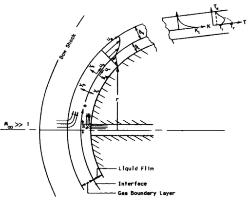
Basic Concepts of Evaporative Film Cooling
A model of evaporative film cooling of a blunt body with stagnation point coolant injection is shown in Fig. I. The coolant is injected over a small area with a radius s0 and the film develops along the solid wall with the thickness δ[_ due to the shear stress on the interface exerted by the gas boun
dary layer with the thickness 6g. Typical calculated values of δ[_ for our experiments are about 0.008 and 0.001 inch in the stagnation point region of the hemisphere or blunt cone, respectively, and between 0.002 and 0.001 inch along the cone surface. Due to the small dimension the film thickness has not been measured on the wind tunnel models, but obtained by calculation. Evaporation occurs at the interface between liq
uid film and gas boundary layer. W e deal with a binary layer which consists of one, two, or somethimes three phases. Water exists in the vapor form, liquid form, and sometimes in the
ice state.
With the following three basic assumptions analytical understanding and calculations have been obtained:
1. The flow in the liquid film is laminar. This is justified because the Reynolds number of the film Rej_ is in the order of 20 near the stagnation point of a sphere and has typical values on the cone of 100 near the tip and of 10 near the base. Waves at the interface should not occur due to the small values of Re(_. They have been observed in (6) at Re[_ ^ 5000. In a flow without pressure gradient we would then have the familiar Couette flow with linear velocity distribution.
Although this condition is no longer exactly true in the neighborhood of the stagnation point, it has been used in the following analysis for simplicity.
2. The shear stress t\ at the interface is equal to the one calculated for the gaseous boundary layer at a porous wall at rest with mass addition equal to the evaporation from the film. This is justified by the fact that the velocity of the liquid at the interface is very small compared to the ve
locity at the edge of the boundary layer, in the order of I 0 "2 near the stagnation point and of ΙΟ-·5 along the cone.
3. The gaseous boundary layer is laminar, which, of course, simplifies the analytical treatment considerably. The assumption is justified by the magnitude of Reynolds number of the experimental investigations presented here; that is, for the hemisphere ReR = 60,000, and for the length of the cone R ex = I χ I 06.
Fig. I shows also a region of the body farther away from the stagnation point with a typical temperature profile, with T] > Te. Film cooling corresponds to the case of a "strongly cooled wall" T j < < T R; for re-entering vehicles the interface
SIXTH SYMPOSIUM ON BALLISTIC MISSILE AND AEROSPACE TECHNOLOGY
118
Figure 1. Schematic of Evaporative Film Cooling of Blunt Body
with Stagnation Point Coolant Injection.
SIXTH SYMPOSIUM ON BALLISTIC MISSILE AND AEROSPACE TECHNOLOGY
temperature is usually slightly above the free stream temper
ature, namely 492°R to about 960°R (see Fig. I I ) .
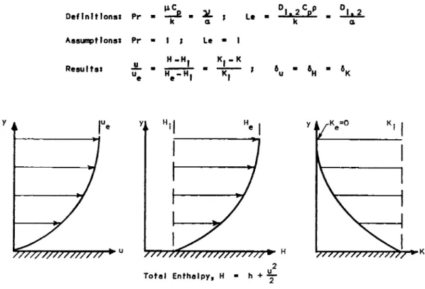
The profiles of velocity u, total enthalpy H, and water vapor mass fraction Κ are shown in Fig. 2. If we assume Pr =
I and also the Lewis number of diffusion of the water vapor into the air Le = I, the profiles are all similar to each other and have equal boundary layer thickness. The profile for the mass fraction is similar but reversed to the two other ones. The similarity is only valid for the profile of the to
tal enthalpy, not for the static enthalpy or static tempera
ture. Note that the heat flux with evaporative film cooling is directed from the gas boundary layer towards the liquid interface, which is opposite to the conventional application of evaporation.
Similarity Analysis of Evaporative Film Cooling for Bodies of Revolution
With the established concepts of heat and mass transfer, an analysis has been developed which permits the calculation of the temperature and water vapor mass fraction at the inter
face, the film velocity and thickness, and the mass flux of evaporation. For the analytical treatment of the two-phase boundary layer we are using the scheme of Fig. I and the as
sumptions stated in the second section. We follow the lines of Lee's analysis of ablation, ( 7 ) , but taking into account the effect of heat blockage by mass addition to the gas bound
ary layer.
Consideration of the convective and diffusive mass flux of the coolant vapor and of the air combined furnishes ( 8 ) , Eq. 16-11:
The corresponding equation for the heat flux expressed in total enthalpy derivative is
Assuming that the PrandtI number and Lewis number are unity, the profiles for total enthalpy Η and mass fraction Κ are sim
ilar; combination of the last two equations gives
(pv). ( 1)
q (2)
(pv). (3)
1 1 9
SIXTH SYMPOSIUM ON BALLISTIC MISSILE AND AEROSPACE TECHNOLOGY
Figure 2. Velocity u, Total Enthalpy H, and Water Vapor Mass Fraction K;
Similar Profiles in Gaseous Boundary Layer for Pr = 1 and Le = 1.
12 0
SIXTH SYMPOSIUM ON BALLISTIC MISSILE AND AEROSPACE TECHNOLOGY
Assuming that the coolant at the wall arrives with the injec
tion temperature and that no heat is convected by the film in flow direction, the heat balance at the interface yields
(pv),
^9’
(4)
Here Lv is the sum of the enthalpy i1 for heating the coolant from the injection temperature to the interface temperature Tj and the enthalpy r for evaporation at T|, or
= ι
+ r (5)In steam tables Ρ is referred to 0°C, Lv is often designated with i" and called "enthalpy of the vapor." For low injection
temperatures (near 0 ° C ) , Lv varies only between ^ 600 and 660 cal/gm 1100 to * ~ 1200 B t u / l bm) in a wide range of temperature (Tf = 0°C to 330°C) or pressure ( pv| = 4.5 to
100,000 mm m e r c u r y ) . Combination of (3) and (4) furnishes
K. =
Η - Η.
L + (H •
e r
ν e H.) (6)
which yields important information. Kj depends essentially on
˜ Η because Lv depends only very little on the pressure or temperature level. It is interesting that K| does not depend on the particular body shape or location, on the coolant flow itic applied, or on the mass flux of the main stream. Our ex
periments have been done up to T0 = 2300°R which furnishes K}
~ 0.25. For ˜ Η » Lv, Kj I. The variation of Kj as a function of stagnation enthalpy for re-entry vehicles will be discussed in the fifth section.
The mass fraction of coolant vapor at the gas-liquid in
terface is expressed as a function of vapor pressure from Dal- ton's law
τ.
= 1 + Μ, Δ( £ - 9
(7)Combination of the equations ( 3 ) , ( 4 ) , and (7) furnishes
ΜΛ / p_
x
LML
I
" V L / Η - Η .e f
(8)
Since pvj , Lv, and Η] are functions of T j , the last equation represents an implicit relationship for T { , and Tj can be cal- culated.
121
SIXTH SYMPOSIUM ON BALLISTIC MISSILE AND AEROSPACE TECHNOLOGY
Evaporation from liquid film into the gas boundary layer reduces the heat flux and shear stress at the gas-liquid inter
face. The ratio of those parameters with and without mass transfer is called the heat blockage factor
ψ
=2a i
=_JL_3l (
9)which for laminar stagnation point flow has been correlated by ( 9 ) :
/ Μ \ 0.26 Η - Η.
ψ = I - 0.68 (
jfj
- | ( p v ) , (10)I Ηο
Combination of ( 4 ) , ( 9 ) , and (10) permits calculation of Ψ . The heat flux q0 in the stagnation point region without mass
transfer can be obtained from various formulas in the litera
ture, for example, from (JJD) using modified Newtonian pressure distribution. In conjunction with ( 9 ) , this furnishes q g j , and with (4) we obtain ( p v | ) .
The velocity Uj at the gas-liquid interface and the film thickness 6L are obtained from the continuity equation for the liquid film and the shear stress equation. The rate of evapo
ration ( p v ) | is eliminated by qg| using the heat balance ( 4 ) , and the shear stress by qgj using Reynolds analogy. Neglect
ing the temperature drop across the liquid film, assuming Tw = T:, we obtain for a body of revolution:
(t)
2. P 7 >2 /3 ζ · p. μ. . r u (Η - H.)
KL H.r ο e e t
/ ( r
(pv) ds - } rτ
2^·
d s ) (II)4 \ °
w4
0 Lv/
and
u. Η - Η . .
δ, = μ, —L H_. u q . g
-I
L (Pr )~Z/ (12)ι e Hg i y
The analysis has been evaluated for a hemispherical (R = 0.5 inch) nose of a cone with a water flow rate mc = 2.2 χ
Ι Ο "4 lbm/sec, for T0 = 1200°R and 2000°R. The results were presented in Fig. 9 and 10 of (5^)· The velocity u*f of the coo
lant at the interface and also the ratio of uj to the velocity
122
SIXTH SYMPOSIUM ON BALLISTIC MISSILE AND AEROSPACE TECHNOLOGY
of the gas at the boundary layer edge was plotted as func
tion of the arc length. This ratio is about 2 χ Ι Ο "2 or smal
ler and hence fulfills the assumptions previously made for this analysis. Uj increases first about linearly with s be
cause ue increases linearly. The coolant film thickness 6j_
has also been calculated as a function of the arc length; it has a maximum value of about 0.001 inch near the stagnation point and then decreases. The mass flux of evaporation ( p v ) | shows a trend similar to the known q-variation with azimuth around a sphere.
Comparison Between Wind Tunnel Experiments and Analysis Models and Wind Tunnel
The experimental investigation was conducted on two hemi
sphere-cylinder models and one cone with either pointed or blunt nose. A 3-inch diameter, hemisphere-cylinder model, in
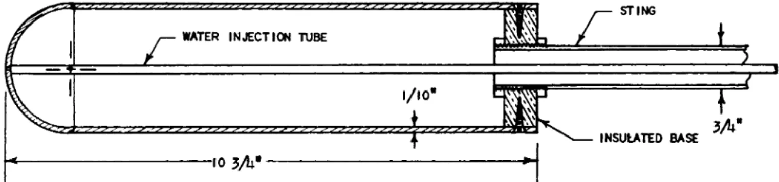
strumented with 15 pressure orifices on the hemisphere, 10 pressure orifices on the cylinder, and 4 thermocouples was used for pressure distribution and preliminary experiments with water injection. The final 3.00-inch diameter hemisphere- cylinder model (Fig. 3) contains 25 pressure orifices and 66 thermocouples to determine the wetted area of the evaporating film.
In order to have flow conditions with constant Mach num
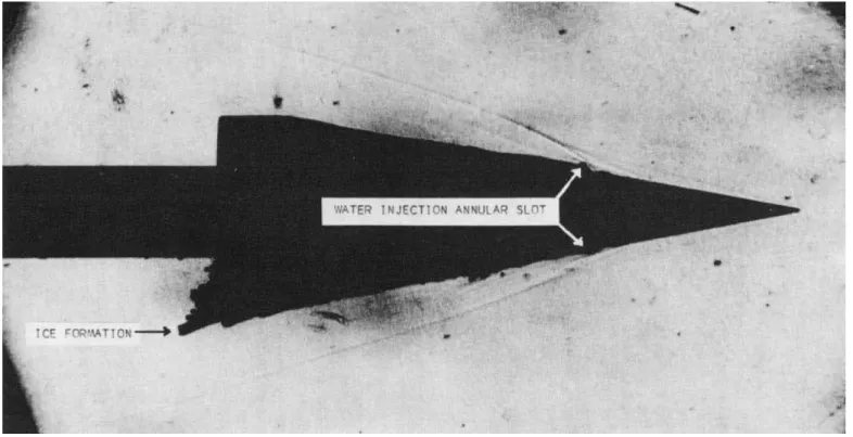
ber and pressure along the surface a cone model built out of alumina oxide was investigated. This is shown in a shadow
graph picture in Fig. 5. The half angle is 10°, its base diam
eter 5.5 inches, and the length of the cone is 15.6 inches.
The cone can be used alternately with a pointed tip or a spher
ical nose. The water mass flow can be controlled by a bevel gear drive operated from the outside of the wind tunnel. With the pointed cone the water is injected through a slot some dis
tance downstream from the tip. With the blunt tip injection is at the stagnation point.
The models have been investigated at Mach number 7 in the hypersonic blowdown wind tunnel of the Rosemount Aeronau
tical Laboratories described in detail in (JJM. A 9a s ^ r ed pebble bed storage heater can produce stagnation temperatures up to 2600°R in the test section at nominal stagnation pres
sures of 10 Atm. The test section contains a two-dimensional contoured Laval nozzle with 12" χ 12" cross section, producing a uniform hypersonic stream of Μ = 7. The running time is 2 minutes. The film cooling investigation was carried out for stagnation temperatures from 1100 to 2500°R.
125
SIXTH SYMPOSIUM ON BALLISTIC MISSILE AND AEROSPACE TECHNOLOGY
Figure 3. Hemisphere-Cylinder Model for Film Cooling Investigations with Instrumentation.
124
SIXTH SYMPOSIUM ON BALLISTIC MISSILE AND AEROSPACE TECHNOLOGY
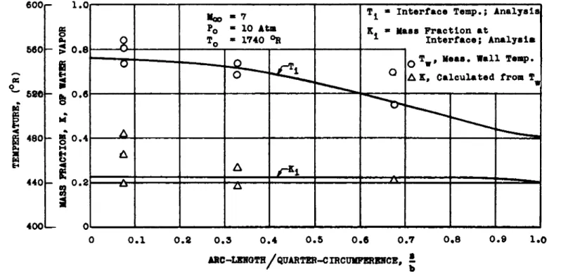
Figure h. Comparison Between Measured Temperature on Wall Surface of Hemisphere and Calculated Temperature of Gas-Liquid
oInterface;
also Mass Fraction K. at Interface; M= 7 , T
Q= 17 ^ R.
125
SIXTH SYMPOSIUM ON BALLISTIC MISSILE AND AEROSPACE TECHNOLOGY
126
Wall Temperature and Mass Fraction at Interface
One primary objective of the investigation is to deter
mine the extent to which the wall can be cooled when film coo
ling is applied. Fig. 4 shows the measured wall temperature of the final hemisphere-cylinder model for Μφ = 7 , P0 = 10 Atm, T0 = I740°R as a function of the dimensionI ess arc length s/b.
The analysis of the third section has been evaluated for the same conditions and compared with the experiments in Fig.
4. It shows the calculated temperatures T| of the gas-liquid interface as a function of the arc length. Near the stagna
tion point the calculated interface temperature is 552°R while the average measured wall temperature is 558°R with a scatter of ll3°R. As seen, the film cooling method is very effective.
The average difference between experimental wall temperatures and analytical interface temperature around the sphere is a- bout +10°F. Hence the theory predicts the temperature of the
interface near the stagnation point and its variation around the sphere very well. The analytical value of the mass frac
tion at the interface Kj does not depend on the arc length up to θ = 8 0 ° , as expected from ( 6 ) . The Kj values calculated from experimental Tw values show a large scattering due to the high sensitivity of Kj relative to Tw, but agree in general with the theoretical ones.
Ice Formation
One of the most interesting phenomena observed in con
junction with evaporative film cooling was the formation of ice on bodies in high temperature hypersonic flow. Water first evaporates in the stagnation region and by diffusion and convection fills the boundary layer. When the flow around the hemisphere is expanding, pressure and temperature inside the boundary layer drop so that conditions for recondensation or even ice mist formation can occur. Under certain conditions this mist may collect and become visible as large ice forma
tions. This phenomena is illustrated for the specific condi
tions shown in Fig, 4. When the calculated line of the inter
face temperature intersects the temperature of the ice point (492°R), water at the interface cannot exist any more as liq
uid and should become ice and sublime from the ice into the gaseous phase.
Typical ice formations on hemisphere-cylinder bodies have been presented previously in Fig. 6 and 7 of ( 5 ) . With
SIXTH SYMPOSIUM ON BALLISTIC MISSILE AND AEROSPACE TECHNOLOGY
12 7
Figure 5. Pointed Cone with 10 Half Angle with Water Film Introduced
on the Cone Surface Showing Ice Formation Near the Bottom
in Conical Sheets; Μ = 7> Τ = 2330 °R (Shadowgraph).
SIXTH SYMPOSIUM ON BALLISTIC MISSILE AND AEROSPACE TECHNOLOGY
stagnation point injection and a rather low stagnation temper
ature ( T0 = 8 6 0 ° R ) , a well defined precise ice formation start
ed at an azimuth of the sphere of about 7 6 ° . When water was injected through 4 orifices at the equator a considerable amount of ice was formed on the rear end of the cylinder body during a run of about 30 seconds with T0 = I360°R. Fig, 5 shows the pointed cone at T0 = 2330°R and Μ = 7 with a water film introduced on the cone surface. The shadowgraph shows ice flakes shortly downstream of the injection area which float, according to a color movie, downstream and eventually collect near the rear end. Note that the ice forms conical sheets with an angle ( 19°) considerably larger than the cone half angle (10°)·
The observed phenomena and measured wall temperatures have been analyzed in a thermodynamic state diagram common to the air flow and the evaporating water film, (5^). A similar diagram is presented in Fig. It showing some experimental
points from wind tunnel investigations and interface conditions for typical re-entry vehicles.
Cone 1 us ions
It has been shown that the analytical values of the interface temperature T; and the mass fraction Kj are in good agreement with measured values of the wall temperature Tw and calculated values of K j . Another important objective is to compare the integrated value of the local mass flux (pv)j with the amount of coolant flow required experimentally to cool a particular body from the stagnation point to a certain down
stream location. The exact value of the minimum amount of coolant needed for the hemisphere or the cone have not been determined. This is a result of experimental difficulties in the determination of the exact length of the film in downstream direction. Limited funds did not permit continuation of exten
sive experiments.
In spite of lack of confirmation of this part of the analysis, it is felt that the theoretical understanding of the processes involved is sufficiently advanced that the applica
tion of the analysis to extreme re-entry conditions, which are beyond the ones measured in the hypersonic wind tunnel, is justified.
128
SIXTH SYMPOSIUM ON BALLISTIC MISSILE AND AEROSPACE TECHNOLOGY
Application of Evaporative Film Cooling to Re-Entry Trajectories
Gliding Vehicle Trajectory in Altitude-Velocity Diagram We want to investigate the application of evaporative film cooling for re-entry vehicles, either for ballistic mis
siles or for gliding vehicles. In particular we will discuss the application to an equilibrium gliding vehicle trajectory.
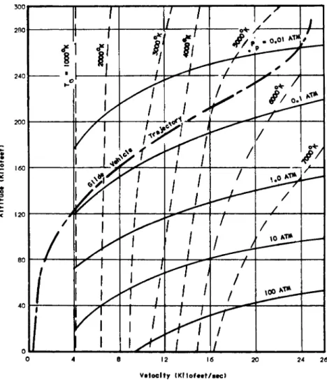
It is now customary to present re-entry trajectories in an altitude v s . velocity diagram (Fig. 6 ) . It is advantageous to
insert the lines of constant stagnation pressure and constant stagnation temperature into the altitude-velocity diagram.
For the calculation of evaporative film cooling parameters we will need the stagnation pressure behind the normal shock, called pitot pressure pp, and the stagnation enthalpy H0. If we disregard the small variations of the static enthalpy of the atmosphere with altitude, the stagnation enthalpy is a function of velocity only. The stagnation pressure, of course, is a function of free stream density ρφ and velocity. In order to avoid uncertainties in the γ value when calculating the pitot pressure with supersonic formulas, we are using the Newtonian pressure approximation
ρ = ρ v2 (13)
κρ <3D
The lines of constant stagnation temperature depend on both velocity and altitude. For calculation it is convenient to select a fixed altitude, that is ρφ , ana use a variable velocity ν to obtain the values of HQ; combination of ν and ρφ determine the pitot pressure pp. For a given pair of pp
and H0 values one reads the stagnation temperature T0 from the Avco chart for equilibrium air, (J_2)« One obtains, therefore,-
for a fixed altitude, T0 as a function of v, from which selec
ted TQ values can be interpolated. Fig. 6 shows that the tem
perature lines at low velocities are vertical, that is, the temperature depends only on velocity. For higher velocities TQ depends on velocity and altitude (density), and the effect of dissociation and ionization at higher velocities can be observed.
Included in Fig. 6 is the trajectory for an equilibrium gliding vehicle with a value of W / S C L = 8 0 psf. The coordi
nates of the trajectory are taken from (J_3) and correspond to one of the upper boundaries of the corridor of permanent flight.
129
SIXTH SYMPOSIUM ON BALLISTIC MISSILE AND AEROSPACE TECHNOLOGY
Figure 6. Gliding Vehicle Trajectory in Altitude-Velocity Diagram with Lines of Constant Stagnation Temperature and Stagnation Pressure.
150
SIXTH SYMPOSIUM ON BALLISTIC MISSILE AND AEROSPACE TECHNOLOGY
The W / S C L- v a l u e can be interpreted in various ways; for in
stance, as having a value of W / CDA = 160 or 240 psf with an L / D = 2 or 3, respectively. This vehicle trajectory is close to the one discussed by Stalder, (_Γ4), Fig. 10a , who investi
gates the combination of W / C Q A = 300 psf with L / D = 3 or W / S CL
= 100 psf. It is an interesting result that a major portion of the gliding vehicle trajectory is approximately parallel to a line pp = constant. The maximum stagnation pressure is only 0.07 Atm, a factor 1000 smaller than the values occurring in ballistic missile re-entry.
Stagnation Pressure for the Gliding Vehicle and Stagnation EnthaIpy
The stagnation pressure of the particular gliding vehi
cle is shown in Fig. 7 as function of the velocity. At the highest velocities the pressure is very low, then increases rapidly and stays approximately constant during the rest of the re-entry. Also presented is the stagnation enthalpy H0 as function of velocity. Because H0 depends essentially on velo
city only, this curve is valid for any trajectory of a re-en
tering vehicle.
Water Vapor AAass Fraction at the Interface and Heat Blockage Parameter
The water vapor mass fraction Kj at the interface can be calculated from (6) of the analysis. The enthalpy terms must be interpreted in the following way:
Obviously pe used in the film cooling analysis is identical to the pitot pressure pp obtained from the trajectory calculations.
Hence, He, the enthalpy at the edge of the boundary layer, is identical to the stagnation enthalpy, or He = HQ, which is a function of velocity only and has to be taken for air only be
cause it is to be evaluated at the edge of the boundary layer with Ke = 0. The enthalpy Hj is to be taken at the interface where the velocity is negligible, hence it is identical to the static enthalpy h ] , or Hj s h j . At the interface we have an
Η - Η. = Η (ν) - Η. (ρ .) e ι ο ι νί
(η
sat ( 14)151
SIXTH SYMPOSIUM ON BALLISTIC MISSILE AND AEROSPACE TECHNOLOGY
Figure 7. Stagnation Enthalpy as Function of Velocity (General); Stagnation Pressure for a
Particular Gliding Vehicle Trajectory (W/SC. = 80 psf).
L
1 5 2
SIXTH SYMPOSIUM ON BALLISTIC MISSILE AND AEROSPACE TECHNOLOGY
air-water vapor mixture and, to be exact, the enthalpy has to be taken for this mixture. The bracket behind hj denotes that the enthalpy has to be taken at a temperature on the satura
tion line of the water vapor, which corresponds to the partial vapor pressure pv| at the interface. For large velocities the enthalpy difference is large and the value of Hj is small com
pared to He. Also, Kj is close to unity, which causes pvj « Pp. Hence, the enthalpy at the interface may be approximated by
h.
Γτ (ρ ,)Ί .
~4 h.[Y
(p )] . (15) ι L v\i\ 1 sat ι I KpJ
satfor pure air at the pitot pressure, which simplifies the cal
culation considerably.
Later we need the ratio between the driving enthalpy po
tential and the enthalpy of the vapor Ly. This ratio can be expressed by Kj using (6) which furnishes
Η - Η , Κ.
-Μ - τττ.
V ί
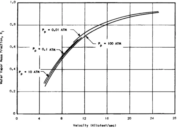
The water vapor mass fraction at the interface is pre
sented in Fig. 8 as a function of re-entry velocity with stag
nation pressure as parameter. Again we have pp « pe. It can be seen that the influence of the pressure on Kj is very small for pressures varying from near the ice point to near the crit
ical point. Kj is increasing strongly with v. For velocities near circular velocity, Kj is approximately 0.91. For very small velocities, Kj 0 (not s h o w n ) .
For the trajectory of the particular gliding vehicle under consideration, velocity and pitot pressure are related according to Fig. 7 . Hence, we obtain in Fig. 9 the variation of Kj with the velocity for this particular vehicle. Of course, this curve is very close to the one in Fig. 8 with pp = 0.1 Atm.
The heat blockage parameter ψ , which can be calculated from the analysis, is of great importance because it character
izes the reduction in heat transfer due to the effect of the mass transfer occurring perpendicular to and away from the
interface. The correlation for laminar stagnation point flow was given in ( 9 ) , Eq. 10. Obviously this is a linearized equation and cannot be used for such large values of the blow
ing parameter, that ψ would become zero or negative. By elim
ination of (ρν)· with the aid of the heat balance equation (4) and introduction of ψ according to its definition ( 9 ) , one obta ins
1 5 5
SIXTH SYMPOSIUM ON BALLISTIC MISSILE AND AEROSPACE TECHNOLOGY
Figure 8. Water Vapor Mass Fraction at Interface as Function of Arbitrary Vehicle Velocity and Stagnation Pressure.
154
SIXTH SYMPOSIUM ON BALLISTIC MISSILE AND AEROSPACE TECHNOLOGY
Figure 9• Water Vapor Mass Fraction at Interface and Heat ELockage Parameter
as Function of Velocity of a Particular Gliding Vehicle (w /SC
L= 8 0 psf).
155 jL«ja4au*jBd a6e>p<?|g \QBH <!M *uo[\09Jd ssew Jod9^ J9\Q^
SIXTH SYMPOSIUM ON BALLISTIC MISSILE AND AEROSPACE TECHNOLOGY
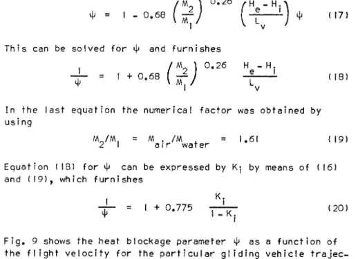
/ Μ \ ° ·2 6 t Η - Η. Λ
ψ
= Ø
. 0 . 6 8 [ 1 ) ψ <| 7>This can be solved FOR ψ and furnishes
/ Μ
1
0.26 Η - Η .— = '+ ·0 6 8 ( mT / 1 V ) ( , 8 In the last equation the numerical factor was obtained by
us i ng
WL/M. = Μ . /M = 1 . 6 1 (19) 2 I air water
Equation (18) for ψ can be expressed by Kj by means of (16) and (19), which furnishes
K,
IR =
1 +° ·
7 7 5ΤΓϊΓ
( 2 0)Fig. 9 shows the heat blockage parameter ψ as a function of the flight velocity for the particular gliding vehicle trajec
tory. At low velocities it is close to unity while at re
entry velocities the blockage factor decreases to 0.1 I as a consequence of the large rate of evaporation. It means that the actual heat transfer qgj is only II per cent of the heat transfer q0 without mass transfer. Correspondingly, the amount of coolant needed for the evaporative film cooling is also reduced to II per cent.
"Effective Heat" of Evaporation of Water for Film Cooling In order to compare various mass transfer schemes to
gether with respective materials or fluids, it has become a custom to introduce a so-called "effective heat" of the mass transfer process, particularly for ablation. Here we intro
duce the equivalent "effective heat of evaporation" of the water for the film cooling process. The effective heat is de
fined by:
a
xe f f (pv).
The dimension of this value would be, for instance, Btu/slug as in the British aeronautical system or B t u / l bm as it is usu
ally given in the heat transfer literature. Introducing into
1J6
SIXTH SYMPOSIUM ON BALLISTIC MISSILE AND AEROSPACE TECHNOLOGY
(21) the equation for the heat balance (4) and the definition of the heat blockage factor ψ (9) leads to the convenient form
Qe f f = IT ) ( 2 2
The units of Qeff are obviously those used for Lv, for in
stance B t u / l bm. To be exact, q0 must be taken at the tempera
ture of the interface with mass transfer cooling present; cor
respondingly, Lv must also be calculated at the temperature of the interface which occurs with mass transfer cooling present.
This temperature depends upon the stagnation pressure, that is, the pressure at the interface, and is determined by the satu
ration line of the water vapor.
Introducing for ψ the value from (18) we obtain the following
Γ / M l 0.26 Η - H. l
Q e f f = Lv [' + · 06 8
(ΐξΙ -^—j
( 2 3)For small enthalpy difference, Oef f is nearly equal to Lv, then increases with ˜ Η and finally is nearly proportional to He- H | , the enthalpy difference itself. O e f f cn also be a expressed by the water vapor mass fraction at the interface K|
and (23) with (16) furnishes
K.
9e f f = Lv U +
° -
7 7 5T U T >
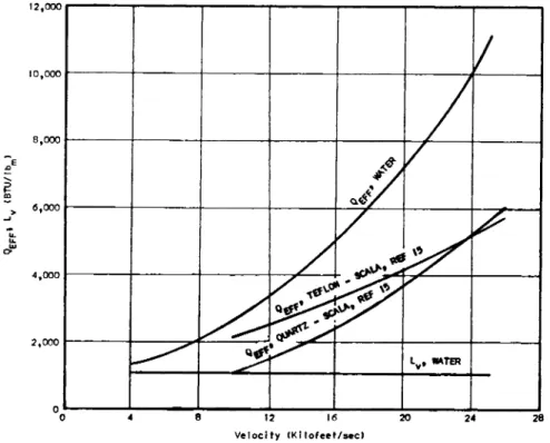
( 2 4)The effective heat of evaporation is shown in Fig. 10 as a function of the velocity. For small velocities it is only somewhat larger than 1100 B t u / l bm, while at re-entry velocities
it increases 10-fold to 11,000 B t u / l bm. This value of Qe ff is in the velocity range from 10,000 ft/sec to 25,000 ft/sec, about twice the effective heat of ablation of teflon, ( 1 5 ) . Pressure-Temperature Conditions at the Interface for Various Re-Entry Vehicle Trajectories
The pressure-temperature conditions which occur at the interface for evaporative film cooling during re-entry for various vehicle trajectories can best be analyzed in a thermo
dynamic state diagram (Fig. I I ) , plotting log pressure v s . log temperature. Shown is the saturation line for water vapor with the "triple point" which occurs at 0.0l°C and at a vapor
1 5 7
SIXTH SYMPOSIUM ON BALLISTIC MISSILE AND AEROSPACE TECHNOLOGY
Figure 10. Effective Heat of Evaporation of Water in a Film Cooling Process Compared with the Effective Heat of Ablation for Teflon and Quartz.
15 8
SIXTH SYMPOSIUM ON BALLISTIC MISSILE AND AEROSPACE TECHNOLOGY
Figure 11. Pressure-Temperature State Diagram vith Saturation and Ice Line for Water; Also Interface Conditions for Three Typical Re-entry Vehicles and Hypersonic Wind Tunnel Results.
1 5 9
SIXTH SYMPOSIUM ON BALLISTIC MISSILE AND AEROSPACE TECHNOLOGY
pressure of 4.5 mm Hg. Above the triple point the saturation line divides the gas from the liquid phase; below, it divides the gas from the solid phase. Also included is the boundary between liquid and solid state above the triple point which is very nearly a vertical line at 0°C. The saturation line fol
lows approximately the equation of Clausius and Clapeyron which, containing some simplifications, is written as ( 1 6 ) , ΡΡ· 172.
In ρ = - r/RT + constant (25) More accurately, the numerical values for water vapor are
found in tables, (J_6), pp. 406, 498. The saturation line ends at the critical point which occurs at Τ = 374.I5°C and a pres
sure of 218.39 Atm. Beyond this point water in the liquid and vapor state cannot be distinguished. The slope in (25) is proportional to the heat of evaporation r for the change of state across the saturation line. Above the triple point r varies somewhat with temperature and has a typical value (at
I00°C) of r = 540 cal/gm or 1000 B t u / l bm. At the triple point its slope has a finite change.
Inserted in the state diagram are experimental points measured by the author on a hemisphere model in a hypersonic wind tunnel and in nozzles installed in a hypersonic wind tun
nel or connected to a combustion chamber, using evaporative film cooling in all three cases. Also included are values calculated for various re-entry vehicles (Fig. I I ) . The ex
perimental points are measured wall temperatures Tw for various configurations and test conditions as indicated. They can be
interpreted as being nearly equal to the temperature of the interface Tj because the temperature change through the thin coolant film is very small. The experimental points have been discussed in detail in relation to the gas flow in nozzles and around the models in the wind tunnel formerly ( 5 ) , Fig. 8.
The experimental points are inserted at the measured wall tem
perature Tw and the measured wall pressure pw, where pw repre
sents the sum of water vapor partial pressure plus the air partial pressure, hence a "total pressure" in thermodynamic terminology. It is an important finding that all experimental points ( Tw, pw) are located somewhat to the left of the satu
ration line. Since the pressure is constant through the boun
dary layer, we have pw = pe.
The thermodynamic state of the interface must lie (with
in a negligible difference due to a finite net evaporation rate which is not discussed further here) on the saturation
line. Hence, the pressure which is obtained at the saturation
140
SIXTH SYMPOSIUM ON BALLISTIC MISSILE AND AEROSPACE TECHNOLOGY
line for Τ = Tw = T; represents the vapor pressure pv} at the interface. And the vertical distance between the experimental point and the saturation line is representative of the ratio of partial vapor pressure to total pressure pv| / pw. The mass fraction at the interface can be calculated from pv} / pe using (7).
Also included are the ranges for the conditions at the interface for three typical re-entry vehicles. The regime for the gliding vehicle (A) is obtained from the stagnation pres
sure range as given in Fig. 7 . The distance of the character
istic line from the saturation line is not entirely to scale.
It depends upon the water vapor concentration at the interface, K j . For the lowest stagnation pressure, corresponding to the highest altitudes and largest velocities, the mass fraction is high, Kj /—' 0.9, and the line will be very close (within 10 per cent of pressure) to the saturation line. For higher pres
sures, that is lower velocities, the mass fraction is smaller, Κ· /—' 0.2, and the characteristic line is more remote from the saturat ion Iine.
The characteristic regions for the ICBM with various ballistic parameters (B, C) are obtained from typical stagna
tion pressure ranges which those I C B M!s are covering. Of course, the ICBM with the highest area loading (C) reaches the highest stagnation pressure ( * ~ 60 Atm) and therefore also the highest temperatures. But even for this extreme case the conditions at the interface are still below the critical point and its wall temperature does not exceed 950°R. It can be noted that the wall temperatures occurring on the gliding ve
hicle stagnation point will stay below 560°R, an extremely low temperature.
At the highest speeds and altitudes the interface condi
tions will come rather close to the ice region; without reach
ing it, however.
Cone Iusions
Based on analytical and experimental investigations we obtain the result that evaporative film cooling is possible for three typical re-entry vehicles ranging from gliding vehicle to ICBM. The thermodynamic conditions at the interface are loca
ted in between the critical point and the triple point of the water vapor, hence the proper functioning of the evaporative
film cooling as presented in this paper should be guaranteed.
At re-entry velocities, water vapor mass fraction at interface is high (Kj/—' 0 . 9 ) , the heat blockage factor very small ( ψ
141
SIXTH SYMPOSIUM ON BALLISTIC MISSILE AND AEROSPACE TECHNOLOGY
Acknowledqement: The author sincerely acknowledges the great efforts and contributions of W . Melnik, Principal Engineer, in the theoretical treatment and evaluation of experimental re
sults; of J. Stankevics, Senior Engineer, in the earlier phase;
and of K. Thompson, Principal Engineer, and M. Luger, Engineer, in the later phase of the experimental investigation.
References
1. Hermann, R.; Leitinger, H.; and Melnik, W.L.: "Design and Construction Problems of a Hypersonic Facility and Preliminary Investigation of Liquid Film Cooling" Univ.
of Minn., Rosemount Aero. Labs. Research Report No, 127, March 1955; or WADC TN 55-507.
2. Hermann, R; Leitinger, H.; and Melnik, W.L.: "Design and Construction of a Gasfired Storage Heater and Investiga
tion of Evaporative Film Cooling on Typical Hypersonic Nozzle Throat Sections" Univ. of Minn., Rosemount Aero.
Labs. Research Report No. 148, July 1958; or WADC TR 5 8 - 376 under similar title.
142
/—' Ο. I I) producing high values of the "effective heat of evap
oration" up to 11,000 B t u / l bm; the possible benefit through dissociation of water vapor still disregarded. During re-entry from circular velocities waIIsprotected by evaporative film cooling encounter temperatures which are very moderate, never above 950°R, and in the case of the gliding vehicle, very cool
(510-560°R). This, of course, presents one of the greatest advantages of evaporative film cooling compared to other mass transfer schemes. The fact that the vehicles skin, with the underlying structure, is kept at low temperatures will avoid thermal stresses and permit simpler and lighter construction.
Further, because the cool skin and structure prevents any heat input into the interior of the vehicle, instrumentation and human passengers, if any, are placed automatically in a comfort
able temperature. Hence, no additional cooling efforts are needed; an important factor if a whole system is considered.
Finally, from the standpoint of aerodynamics and control, the aerodynamic shape of the leading edge of wings and control sur
faces and of the nose of the fuselage are fixed and kept intact during the entire flight, in contrast to ablation; a most im
portant factor for gliding vehicles with controlled re-entry and landing.
SIXTH SYMPOSIUM ON BALLISTIC MISSILE AND AEROSPACE TECHNOLOGY
3. Hermann, R.; Melnik, W . L . ; and Stankevlcs, J.O.A.: "Re
search on Evaporative Film Cooling of a Mach Number 7 Contoured Wind Tunnel Nozzle in the Rosemount Aeronauti
cal Laboratories Hypersonic Facility" Univ. of Minn., Rosemount Aero. Labs. Research Report No. 173, October
1959; or WADD TR 60-251.
4. Leitinger, H.: "An Estimate of the Thickness of the Coolant Film on an Evaporative Film Cooled Laval Nozzle Throat Section for Mach Number 7" Research paper, Dept.
of Aero. Eng., Univ. of Minn., September 1957.
5. Hermann, R.: "Evaporative Film Cooling of Blunt Bodies in Hypersonic Flow and its Application to Re-Entry Vehi
cles" Paper 23 from the Xlth International AstronauticaI Congress Stockholm I960 proceedings, pp. 215-226, 15-20 August I960, Springer-VerIag, Vienna.
6. McManus, H.N., Jr.: "Film Characteristics and Dimensions in Annular Two-Phase Flow" Proceedings of the 6th Mid
western Conference on Fluid Mechanics. Univ. of Texas, 1959, pp. 292.
7. Lees, Lester: "Similarity Parameters for Surface Melting of a Blunt Nosed Body in a High Velocity Gas Stream" Am.
Roc. Soc. J., V o l . 29, No. 5, May 1959, pp. 345-354.
8. Eckert, E.R.G.; and Drake, R.M.: "Heat and Mass Trans
fer" McGraw-Hill, New York, 1959.
9. Bethe, H.A.; and Adams, Mac C : "A Theory for the Abla
tion of Glassy Materials" Avco R e s . Lab., Research R e port No. 3 8 , November 1958.
10. Fay, J.Α.; and Riddel 1, F.R.: "Theory of Stagnation Point Heat Transfer in Dissociated Air" J. of Aero.
Sciences, V o l . 2 5 , 1958, pp. 73-85, 121.
11. Hermann, R.; Stankevics, J.O.A.; Melnik, W.L.; and Luger, M.A.: "Design, Calibration, and Simulation Capability of the Rosemount Aeronautical Laboratories1 High Tempera
ture Hypersonic Facility" Univ. of Minn., Rosemount Aero. Labs. Research Report No. 172, October 1959; or WADD TN 60-108.
12. Feldman, Saul: "Hypersonic Gas Dynamic Charts for Equi
librium Air" Avco R e s . Lab., January 1957.
13. Hermann, R.: "Problems of Hypersonic Flight at the R e - Entry of Satellite Vehicles" IXth International Astro- nautical Congress. Amsterdam 1958 proceedings, Springer-
145
SIXTH SYMPOSIUM ON BALLISTIC MISSILE AND AEROSPACE TECHNOLOGY
144
V e r l a g , Vienna 1958, p p . 7 6 4 - 7 8 4 . A l s o U n i v . of M i n n . , Rosemount A e r o . L a b s . Research Report N o . 153, November
1958.
14. Stalder, Jackson R.; G o o d w i n , Frederick K.; R a g e n t , B o - r i s ; and N o b l e , Charles E . : "Aerodynamic Applications of Plasma Wind Tunnels" WADD TN 6 0 - 1 , December I960.
15. Scala, Sinclaire M.: "A Study of Hypersonic Ablation"
GE R 5 9 S D 4 3 8 , September 3 0 , 1959.
16. Schmidt, E . : "Thermodynamic" Springer-VerIag, B e r l i n , G o t t i n g e n , Heidelberg. 7th E d i t i o n , 1958.