Nonlinear System Control Using Neural Networks
Jaroslava Žilková, Jaroslav Timko, Peter Girovský
Department of Electrical Drives and Mechatronics Technical University of Košice
Letná 9, 042 00 Košice, Slovak Republic
jaroslava.zilkova@tuke.sk, jaroslav.timko@tuke.sk, peter.girovský@tuke.sk
Abstract: The paper is focused especially on presenting possibilities of applying off-line trained artificial neural networks at creating the system inverse models that are used at designing control algorithm for non-linear dynamic system. The ability of cascade feedforward neural networks to model arbitrary non-linear functions and their inverses is exploited. This paper presents a quasi-inverse neural model, which works as a speed controller of an induction motor. The neural speed controller consists of two cascade feedforward neural networks subsystems. The first subsystem provides desired stator current components for control algorithm and the second subsystem provides corresponding voltage components for PWM converter. The availability of the proposed controller is verified through the MATLAB simulation. The effectiveness of the controller is demonstrated for different operating conditions of the drive system.
Keywords: Artificial neural network, control methods, non-linear dynamic system, induction motor, speed control
1 Introduction
In recent years artificial neural networks (ANNs) have gained a wide attention in control applications. It is the ability of the artificial neural networks to model non- linear systems that can be the most readily exploited in the synthesis of non-linear controllers. Artificial neural networks have been used to formulate a variety of control strategies [4], [5].
There are two basic design approaches:
• Direct inverse control – it uses a neural inverse model of the process as a controller.
• Indirect design – the controller uses a neural network to predict the process output.
squirrel-cage induction motor.
2 The Inverse Model of a Dynamic System
Although the system inverse model plays an important part in the theory of control, the attainment of its analytical form is pretty strenuous. Anticipating that a dynamic system can be described by the differential equation
(
k 1)
f[
y( )
k , ,y(
k n 1) ( )
,uk , ,u(
k m 1) ]
y + = K − + K − + (1)
where the system output y(k+1) depends on the preceding n-output and m-input values, the system inverse model can be generally presented in the following form
( )
k f 1[
r(
k 1)
,y( )
k , ,y(
k n 1) ( ) (
,u k ,u k m 1) ]
u = − + K − + − + (2)
Here y(k+1) is an unknown value, and hence can be substituted by the output quantity desired value r(k+1). The simplest way to arrive at a system inverse neural model is it to train the neural network to approximate the system inverse model.
In real life, the most frequently used are two concepts of inverse neural model architecture: the ‘general training’ architecture (Fig. 1), and the ‘specialized training’ architecture (Fig. 2), respectively.
If in the general training architecture, signal u is applied to the system input, signal y is obtained at the system output. The different between the incoming signal u and the neural model output uN is the error eN which can be utilized for network learning.
Figure 1
The ‘general training’ architecture
Figure 2
The ‘specialized training’ architecture
Contrary to the previous approach, it is error ec that is in the ‘specialized training’
architecture utilized for neural network training. Error ec is here obtained as the difference between the desired input signal r and the signal y that represents the actual system output.
The former of the two methods brings several substantial disadvantages:
The selection of varying output signal y values, specified for training of the network, cannot guarantee that the trained system output will fall exactly into those regions that are important for its successful utilization in controlling.
If the controlled system happens to be multidimensional, the attained model that is represented by the inverse neural model may be incapable of imitating a real system.
The above outlined drawbacks can be circumvented by the letter method – the
‘specialized training’ architecture-that yields some advantages when compared with the former one:
The method (Fig. 2) is intended directly for controlling, whereas the training signal is formed in dependence on the difference between the system desired and real outputs.
In the case of multidimensional dynamic system, the real inverse model can closely simulate a real system.
Multi-layer neural networks can be utilized when creating a system inverse neural model. The use of the MLP type static neural networks presents the simplest solution, however the representation of the system dynamic remains problematic with this neural model. The application of a MLP type neural network with time delaying of the input layer signals can present the solution for introducing the process dynamics into MLP type static neural network. The solution falls among the simplest ones, and the advantage of utilizing this network type rests with the opportunity of its training by traditional backpropagation algorithm for multi-layer networks.
voltage (rectified via using an uncontrolled rectifier).
Figure 3
The scheme of the neural controller
Since the neural controller output in such a structure is not directly equal to voltage fed into the motor we have abandoned the idea to establish an accurate inverse model; considered for input quantity of the quasi-inverse neural model were rather the desired and at a time also real (measured) motor speed (Fig. 3).
The design of the neural controller is based rightly on known values of these speeds.
A typical technique for control synthesis purposes is based on using a description of the induction motor in rotating reference frames (x, y). The use of such rotating reference frames has the benefit of simplifying the model of the motor from the point of view of controller design.
In this section design of the neural controller will be presented. The speed controller consists of two neural networks subsystems with backpropagation learning algorithm. The first subsystem (Fig. 4) of the controller serves for desired current components reconstruction and the second subsystem serves for corresponding voltage components reconstruction for PWM converter. These voltage components present action intervention for PWM modulation that would make up the desired stator voltage values from the mains voltage (rectified using an uncontrolled rectifier). The overall control structure is shown in Fig. 3.
Figure 4
Concept of the neural controller
3.1 Identification of Stator Currents
The first subsystem ANN1 consists of two neural networks ANN1.1 and ANN1.2, according to equations (3). The networks are trained to approximate the time- varying function of f 1 and f2 to give estimated one-step-ahead predicted stator current components:
( ) ( ) ( )
( )
= ⎢⎣⎡( ) (
−)
⎥⎦⎥⎦⎤⎢⎣ ⎤
⎡ −
=
w , 1
* k ,
* k 2 f
* k isy
w , 1
* k ,
* k 1 f
* k isx
ω ω
ω ω
(3)
The inputs of the first neural subsystem ANN1 are values of desired angular speed, in k-th and (k-1)th step. The three layers feedforward neural network (FFNN) with one hidden layer has been elected, in first step, to approximate the non-linear function f.
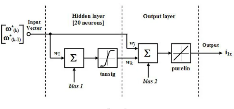
Further working showed that cascade feedforward neural networks (CFNN), which outputs a1(k) from 1st and a2(k) from 2nd layer of a CFNN are given by:
( ) ( )
( )
k purelin(
Iwj a1( )
k wk bias2)
a2
bias1 wi I sig k tan a1
+ +
=
+
=
(4) where I is input vector and w represents weights of the network, with one hidden
layer reached the better approximation properties then FFNNs.
The structure of the cascade network ANN1.1 is shown in Fig. 5. The structure of ANN1.2 is identical.
The hidden layer of the cascade network contains twenty neurons with tansig nonlinear activation function. The neurons of the subsystem ANN1 outputs have linear activation function.
Figure 5 The structure of the ANN1.1
3.2 Rotor Speed Control
Measured actual stator current (3) corrects desired value of stator current:
( ) ( )
k i k i( )
k is =*s − sΔ (5)
Resulting signal of the correction:
( )
*( )
k is( )
k issc k
i = +Δ (6)
in k-th and (k-1)th steps and the desired speed value present inputs to the second ANN2, which generates appropriate voltage values for PWM converter:
(
k+1)
=g⎢⎣⎡isc( ) (
k i,sc k−1)
, *,w⎥⎦⎤us ω (7)
The cascade feedforward neural network is used for g approximation, too. The relation (7) determines the number of inputs of ANN2. Twenty hidden neurons in one hidden layer of the neural subsystem employ the hyperbolic tangent function.
The structure of the ANN2 is shown in Fig. 6.
The ANN’s may be trained on-line or off-line. In the case of the off-line training, one requires the input-output characteristics of the system. Training patterns for speed controller were obtained by numerical simulations of the induction motor model with help of MATLAB-Simulink. In simulations the nominal data of a 3kW induction motor were used. All the networks are trained off-line in order to minimise the control performance. The backpropagation training algorithm with Levenberg-Marquardt´s modification was used for the training modes.
Figure 6 The structure of the ANN2
4 Simulation Results
Presented in this section will be the results obtained in MATLAB environment for given connection of the control diagram shown in Fig. 3, where the designed neural controller was implemented. The testing of the neural controller was performed on the induction motor with the following parameters:
U = 220 V/50 Hz, IN = 6.9A, PN = 3 kW, nN = 1420 RPM, R1 = 1.81 Ω, R2 = 1.91 Ω, L1σ = L2σ = 0.00885 H, Lh = 0.184H, pp = 2, TN = 20.17 Nm, JN = 0.1 kgm2.
The neural speed controller was trained in the wide range of speed and load torque changes. Then the trained controller was tested for speed reference signal different than used in the training procedures. These testing signals together with results of simulations are presented in Figs. 7 and 8. Fig. 7 shows speed response waveforms in a case of speed variation. The command speed is 120, -30, 20 and 50 rad/sec, respectively. Fig. 8 shows speed response waveforms in a case of load variation.
The command speed is 100 rad/sec, that is increased from zero speed and the 100% rated load is applied at 1sec and 150% rated torque is applied at 2 sec.
Figure 7
Drive system response under a variable speed reference and actual motor speed
Figure 8
Speed response under load changes
Conclusion
In this paper, an off-line neural network controller for induction motor drives was presented. The design of neural controller is based on sensor information pertaining to angular speed and stator current of the induction motor. The neural controller consists of two cascade feedforward neural networks subsystems.
First subsystem of the neural controller serves for desired current components reconstruction and the second subsystem serves for corresponding voltage components reconstruction for PWM converter.
Cascade feedforward neural networks are used for all functions approximations.
Used with these networks was learning by use of Levenberg-Marquardt algorithm.
Training samples for the speed controller were attained via simulation of an induction motor model in MATLAB-Simulink environment. Simulation results using MATLAB verify the effectiveness of proposed controller.
Acknowledgements
Authors gratefully acknowledge support of VEGA 1/2177/05 at this work.
References
[1] P. Branštetter, M. Skotnica: Application of artificial neural network for speed control of asynchronous motor with vector control, Proceedings of International Conference of Košice, EPE-PEMC 2000, pp. 6-157-6-159 Sept. 2000
[2] M. A. Brdys, G. J. Kulawski: Dynamic Neural Controllers for Induction Motor, IEEE Transactions on Neural Networks, Vol. 10, No. 2, pp. 340- 355, 1999
[3] B. Burton, R. G. Harley, G. Diana, J. L. Rodgerson: Implementation of a Neural Network to Adaptively Identify and Control VSI-Fed Induction Motor Stator Currents, IEEE Transaction on Industry Applications, Vol. 34, No. 3, May/June 1998
[4] A. U. Levin, k. s Narendra: Control of Nonlinear Dynamical Systems Using Neural Networks: Controllability and Stabilization. IEEE Transactions on Neural Networks, 1993, Vol. 4, pp.192-206
[5] A. U. Levin, k. s Narendra: Control of Nonlinear Dynamical Systems Using Neural Networks- Part II: Observability, Identification and Control. IEEE Transactions on Neural Networks, 1996, Vol. 7, pp. 30-42
[6] J. Timko, J. Žilková, D. Balara: Applications of Artificial Neural Networks in Electrical Drives. (in Slovak), Calypso s.r.o., Košice, 2002, p. 239
[7] P. Vas: Artificial-Intelligence-based Electrical Machines and Drives.
Oxford University Press, Oxford, 1999
[8] M. Vittek, J. Rapšík, Buday: Shaft Sensorless Direct Vector Control of Induction Motor with Forced Dynamic. Proc. EPE-PEMC’02, Cavtat &
Dubrovnik, Croatia, CD-ROM, Sept. 2002
[9] M. T. Wishart, R. G. Harley: Identification and Control of Induction Machines Using Artificial Neural Networks. IEEE Transaction on Industry Applications, Vol. 31, No. 3, May/June 1995
List of Symbols and Abbreviations PN - nominal power
TN - nominal load torque
- desired value
R1, R2 - stator and rotor resistances L1, L2 - stator and rotor inductance Lh - mutual inductance
[i1x i1y] - x , y components of stator current [ux uy] - x , y components of stator voltage I – input vector
w – synaptic weight
ANN - artificial neural networks FFNN - feedforward neural network
CFNN - cascade feedforward neural network