B Y
B E N J A M I N B . D A Y T O N
Distillation Products, Inc., Rochester, New York
CONTENTS
Page
1. Introduction 334 2. The Measurement of Low Pressures 334
2.1. Range of Common Types of Vacuum Gauges 334
2.2. Absolute Gauges 334 2.3. Analysis of Gases with Nonabsolute Gauges 338
2.4. Measurement of Ultimate Vacuum 338 2.5. Theory of the Pirani and Thermocouple Gauges 339
2.6. The Construction and Calibration of McLeod Gauges 341 3. The Production of Low Pressures and the Transfer of Gases 344
3.1. Types of Pumps Available Commercially 344 3.2. Mercury Operated Pumps for Analytical Work 346
3.3. Pumping Water Vapor 348 3.4. Traps and Baffles 349 3.5. Assembly of Vacuum Systems 350
3.6. The Flow of Gases through Vacuum Pipe Lines and Absorption Tubes 350 3.7. The Circulation and Transfer of Gases with Diffusion Pumps and
Toepler Pumps 352 3.8. Mercury Cut-Offs, Needle Valves and Stopcocks 353
3.9. Manostats 354 3.10. Outgassing and Leak Hunting 354
4. The Vacuum Fusion Method for the Analysis of Gaseous Elements in Metals 356
4.1. History and General Principles 356
4.2. Apparatus 357 4.3. Procedure 361 4.4. Limitations and Accuracy 361
4.5. Extension to Nonferrous Metals 362 5. Determination of Carbon by the Low-Pressure Combustion Method 362
5.1. General Principles 362 5.2. Apparatus and Procedure 363 5.3. Limitations and Accuracy 365 6. The Microanalysis of Gases at Low Pressures 366
6.1. Methods of Langmuir and Ryder 366 6.2. Methods of Prescott and Morrison 368 6.3. Low Temperature Method of N. R. Campbell 370
6.4. Other Methods and Special Techniques 372 333
Page
7. Analytical Molecular Distillation 373 7.1. Boiling Points and the Elimination Curve 373
7.2. The Cyclic Molecular Still 377 7.3. Future of the Elimination Curve Technique 378
8. Miscellaneous Vacuum Techniques Used in Analysis 378
References 380
1. I N T R O D U C T I O N
Several of t h e unit operations described in other chapters involve vacuum techniques. I t is the purpose of this section t o outline t h e proper methods of assembly and operation of v a c u u m systems constructed with t h e aid of modern diffusion p u m p s a n d unit p a r t s available from manufacturers of scientific glass a p p a r a t u s a n d v a c u u m equipment. This outline is supplemented b y a fairly complete bibliography on v a c u u m technique. As examples of typical v a c u u m systems certain unit opera
tions not described elsewhere in this volume will be briefly treated.
2. T H E M E A S U R E M E N T O F L O W P R E S S U R E S
2.1. Range of Common Types of Vacuum Gauges
T h e adjacent diagram (Fig. 1) shows t h e useful range of pressure measurement for various common types of v a c u u m gauges (8, 12).
T h e width of t h e b a n d indicates t h e relative accuracy of t h e gauge at a given pressure. T h e pressure scale is logarithmic from 10~8 to 102 millimeters of mercury. Among t h e other types not shown on t h e chart are glow discharge tubes (2, 31, 41), which give a rough estimate of pressure in t h e range from 10~2 t o 10 mm., a n d Gaede's " Molvacuumeter "
(100), which is a special t y p e of radiometer gauge with a range from 10~7 t o 10 m m . T h e Alphatron (83, 144, 154) is a new t y p e of ionization gauge using t h e alpha particles from a radioactive source t o ionize t h e gas.
2.2. Absolute Gauges
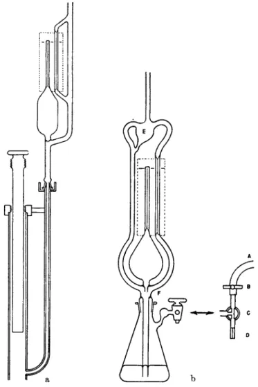
T h e McLeod gauge (1, 6, 193) (Fig. 2a and b), the mercury manometer (1, 92, 212, 227), and t h e butyl p h t h a l a t e (or oil) m a n o m e t e r (69, 109, 116, 203) are " a b s o l u t e " gauges, t h a t is, t h e y measure t h e pressure directly in a way t h a t can be predicted from t h e geometry of t h e instru
m e n t and have t h e same calibration for all gases (except t h a t t h e McLeod gauge can not be used with gases or vapors which deviate considerably from t h e ideal gas law). These three are in general t h e only gauges which can be trusted for analytical work in which t h e pressure enters into t h e final calculations. T h e other types of v a c u u m gauge do not measure t h e pressure directly, b u t rather some other physical property
of t h e gas such as t h e t r a n s p o r t of h e a t (Pirani a n d thermocouple gauges) or t h e ionization produced b y a stream of electrons (ionization a n d Philips gauges). T h e y are usually calibrated against a McLeod gauge on a manifold with cold t r a p s t o eliminate vapors, a n d t h e calibration
ΚΓ* i<rT ίο-· io-» ίο-4 ιο-* κτ* ιοΗ ιο° ιο' ιο*
I O N I Z A T I ON G A U G E I I
R A D I O M E T ER G A U G E i n L I Q U ID A I R
Q U A R TZ M E M B R A NE V I S C O S I TY G A U G E L A R GE B U L B M C L E OD G A U G E
RADIOMETER ( K N U D S E N) G A U GE
i ι ι ι
PIRANI GAUGE i n L I Q U ID A IR P H I L I PS GAUG E |
I I I I Q U A R TZ F I B E R V I S C O S I TY G A U GE
ι ι ι ι I
M E D I UM B U L B D O U B LE RANGE M C L E OD G A U GE
I Ί 1
1ι ,
PIRANI GAUG E - C O M P E N S A T ED A T Z E R O THERMOCOUPLE G A U G E
ι ι A L P H A T R ON
P I R A NI G A U G E - C O M P E N S A T ED A T I MM .
S M A LL B U L B M C L E O D GAUGE
ι ι ι — ι — Γ
B U T YL P H T H A L A TE M A N O M E T ER ι ι — — B O U R D ON T Y P E G A U G E
MERCURY M A N O M E T ER
ιο"· iorT κτ· ιο'* tor4 ιο-' ίο-* lor1 ι ο0 ισ' ισβ
MM. O F HG.
FIG. 1. Range of vacuum gauges.
factor is n o t t h e same for all gases. T h e construction a n d calibration of McLeod gauges is described briefly in Section 2.6.
T h e K n u d s e n gauge is sometimes classed as a n absolute gauge, b u t its calibration varies slightly with different gases because of differences in t h e accommodation coefficient a n d other factors (6, 38, 84, 97).
There are m a n y variations in t h e design of K n u d s e n gauges, which are also known as radiometer gauges (70, 96, 97, 121, 140) a n d K l u m b a n d Schwarz (131) have described a t y p e involving a suspended cylindrical vane system with a heater inside and liquid air cooling on t h e outside
FIG. 2. a) McLeod gauge (long form), b) McLeod gauge (short form).
capable of measuring to less t h a n 1 0- 7 m m . of Hg. T h e principle of operation of Knudsen gauges is to move a suspended vane system b y directing rapidly moving molecules, which have come in contact with a hot surface, against one side of the vanes while less energetic molecules coming from a cool surface impinge on t h e opposite side (132, 208).
.1 . 2 . 3 . 4 . 5 . 6 . 7 . 8 . 9 1. 0 0 - . 7 5 M M. S C A L E R E A D I N G
a
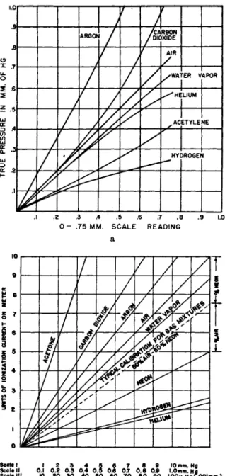
FIG. 3 . a) Calibration of Pirani gauge, type PG-1 A, for various gases. (Distilla- tion Products, Inc.) b) Calibration of Alphatron for various gases. (National Research Corp.)
2.3. Analysis of Gases with Nonabsolute Gauges
While it is possible t o t a k e a d v a n t a g e of t h e fact t h a t t h e " n o n - a b s o l u t e " gauges have different calibration curves for various gases in analyzing simple gas mixtures, t h e accuracy obtainable is n o t very good unless extreme precautions are taken t o eliminate variations in t h e calibration due t o surface changes (accommodation coefficient, etc.)
presence of vapors from rubber or grease exposed in t h e system, fluctua
tions in t h e power supply, electrical leakage, electrical clean-up, e t c . While t h e s t a n d a r d types of ionization gauge (1, 6, 12, 86, 152) h a v e been calibrated for various gases, this gauge is very unreliable because of clean-up effects (7, 56, 183). Calibration curves for t h e Pirani gauge (Type PG-1A) a n d a radioactive-source ion gauge (Alphatron) for various gases are shown in Fig. 3a a n d b .
Corrosive gases react with t h e metal p a r t s of gauges a n d even rela
tively inert gases (e.g., carbon dioxide) m a y react with t h e incandescent filament of t h e ionization gauge. F o r analytical work with extremely corrosive gases such as bromine a n d chlorine a t low pressures t h e quartz- fiber viscosity gauges (12, 38) are recommended since these can b e m a d e with all exposed surfaces of glass or quartz (Fig. 4).
2.4. Measurement of Ultimate Vacuum
I t is frequently necessary t o evacuate a system t o as low a pressure as possible (ultimate vacuum) before admitting a gas sample or reagent.
FIG. 4. Q u a r t z - f i b e r v i s c o s i t y g a u g e .
A n y of t h e gauges listed (except t h e McLeod) can be safely used t o determine when t h e system is sufficiently evacuated t o permit filling with some gas at a pressure over one hundred times t h e u l t i m a t e v a c u u m t h a t can be measured with t h e gauge. However, while t h e usual Pirani gauge (6, 12, 31, 68, 87) or thermocouple gauge (1, 148, 177) can be read down t o 1 micron (0.001 mm.) of mercury or lower, these gauges are subject t o zero shifts of as m u c h as 2 or 3 microns or more a n d hence an ionization gauge is t o be preferred for checking t h e ultimate v a c u u m when gases are t o be introduced at pressures less t h a n 100 microns. T h e hot-filament t y p e ionization gauge is used when pressures less t h a n 10~5 m m . of H g m u s t be reached. T h e cold-cathode type, or Philips ionization gauge (165, 166, 167), has a shorter range as shown in Fig. 1 b u t has t h e a d v a n t a g e t h a t there is no filament t o b u r n out b y accidental exposure t o high pressures. Briefly, t h e principle of t h e Philips gauge is t h e measurement of t h e current t r a n s m i t t e d through a glow discharge in t h e gas excited b y voltages of a b o u t 2000 volts in t h e presence of a magnetic field t h a t lengthens t h e p a t h of t h e moving electrons, t h u s main- taining t h e discharge t o lower pressures t h a n are permitted in an ordinary Geissler t u b e .
T h e McLeod gauge does not show t h e presence of condensable vapors (95), a n d unless t h e system is completely protected at all times with a liquid air or dry ice t r a p t h e t r u e pressure in t h e system is frequently somewhat higher t h a n t h a t indicated b y t h e McLeod gauge. I n general, vapors from oils, " v a c u u m " greases, a n d rubber, and " v i r t u a l l e a k s " (38) due to frosted cold traps are t h e chief sources of trouble in a high v a c u u m system. These can always be detected b y comparing t h e reading of a McLeod gauge and some other t y p e of manometer which does not con- dense t h e vapors, or b y other procedures such as plotting t h e r a t e of rise of pressure on a Pirani gauge when t h e system is isolated b y valves.
2.5. Theory of the Pirani and Thermocouple Gauges
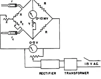
T h e Pirani gauge consists of a W h e a t s t o n e bridge circuit, Fig. 5, to indicate t h e change in resistance of a heated filament (of tungsten, platinum, nickel, or other stable metal with large t e m p e r a t u r e coefficient of resistance) m o u n t e d in a t u b e a t t a c h e d t o t h e v a c u u m system. T h e thermocouple gauge, Fig. 6, measures changes in t h e t e m p e r a t u r e of a heated filament b y means of a thermocouple junction welded t o t h e center of t h e filament. T h e sensitivity formula for b o t h gauges depends on t h e n a t u r e of t h e gas through t h e factor
/ = 4.38 X 10 5 , — in c.g.s. units
where Cv is t h e specific heat of t h e gas at constant volume per mole, R is t h e molar gas constant 8.315 Χ ΙΟ7, Μ is t h e molecular weight of t h e gas, T' is t h e temperature of the gas at the entrance t o t h e Pirani or thermocouple tube, and a is t h e accommodation coefficient (128, 141).
When the heat lost by conduction to the filament supports is negligible,
115 ν A. C
RECTIFIER TRANSFORME R
FIG. 5. Pirani gauge circuit.
it can be shown (87) t h a t t h e rate of change of filament temperature, T, with pressure, p, is
dT = —f(T - To) dp ±ekT*+fp
where To is the wall temperature, k the Boltzmann radiation constant, and e is the total emissivity coefficient. At low pressures and high filament temperatures the t e r m / p in t h e denominator can be neglected.
T h e change in filament temperature, dT, is measured as a change in resistance, dr, on t h e Pirani gauge and as a change in electromotive force, dV, on t h e thermocouple gauge. Since dr/dT = r0a, where ro is t h e filament resistance at Τ = 273° absolute a n d a is t h e linear t e m p e r a t u r e coefficient of resistance, the rate of change of filament resistance with pressure, dr/dp, is obtained by multiplying t h e above formula for dT/dp by r0a. Similarly the rate of change of E M F with pressure for t h e thermocouple gauge is obtained from dV/dp = (dV/dT) (dT/dp) where
7 = («ι - a2){T - To) + Ηβι - β 2)(Τ - To)2 is t h e ordinary formula for the E M F produced by two metals with thermoelectric coefficients cti, ot 2, βi, and β 2 when the hot junction is at t e m p e r a t u r e Τ a n d t h e cold junction at t e m p e r a t u r e To. F r o m these equations t h e response of t h e
gauges for any gas could be predicted except for t h e fact t h a t t h e emis- sivity, e, and accommodation coefficient, a, depend on t h e condition of t h e surface of t h e filament a n d m u s t be determined experimentally for each filament and each gas.
T h e sensitivity of t h e gauges can be increased b y lowering t h e wall t e m p e r a t u r e T0. N o r m a l variations in room t e m p e r a t u r e do not change t h e sensitivity by more t h a n a few per cent. For
example, at t h e higher pressures, as To increases the filament t e m p e r a t u r e Τ also increases so t h a t Τ — To is nearly constant (when t h e w a t t input t o t h e fila
m e n t is constant), and t h e q u a n t i t y (T - To)/Tz is only slightly decreased because Τ is in absolute units.
I n t h e Pirani gauge t h e main purpose of t h e com
pensating t u b e is to decrease t h e effect of variations in the bridge voltage and t o prevent slight zero shifts with changes in room t e m p e r a t u r e . T h e gauge is usually operated b y calibrating t h e galvanometer deflection in t e r m s of pressure. T h e galvanometer current is proportional t o t h e resistance change dr and also t o t h e voltage drop across t h e filament. I t is inversely proportional to a t e r m involving t h e resist
ances of t h e arms and t h e galvanometer resistance.
T h e resistance of each arm and t h e galvanometer
resistance should all be approximately equal for m a x i m u m sensitivity.
2.6. The Construction and Calibration of McLeod Gauges Since t h e McLeod gauge serves as t h e laboratory standard for calibrat
ing other gauges and is t h e principal gauge used in analysis a t low pres
sures, t h e construction and calibration of this gauge deserves special attention. Barr and Anhorn (1) h a v e presented an excellent t r e a t m e n t of this topic and t h e reader should also consult Dunoyer (6).
A m e t h o d of sealing t h e t o p of t h e closed capillary b y fusing a fitted plug of glass to obtain a flat closure is illustrated b y Barr a n d Anhorn and was originally described b y Ferguson (93). This reduces t h e zero error introduced b y a rounded closure a n d also b y bulbous tips which m a k e difficult t h e adjustment of t h e t o p of t h e closed capillary t o t h e zero line.
Another i m p o r t a n t element of construction is a sharp cut-off which m a y be obtained b y adding an orifice b y means of a ring seal just above t h e opening t o t h e side a r m as shown in Fig. 2a, and a t (F) in Fig. 2b, a n d also in t h e article b y Barr and Anhorn. This orifice also diverts air bubbles which sometimes rise with t h e mercury along t h e t u b e wall below t h e cut-off. For large sensitive McLeod gauges Rosenberg (180) recom-
MA r**:
-0 s
FIG. 6. Thermocou
ple gauge circuit.
mends grinding t h e capillaries with N o . 600 Alundum to reduce the stick
ing of t h e mercury. Care must be taken, however, t o avoid the use of coarse h a r d abrasives such as Carborundum, which m a y introduce deep pits in t h e capillary wall t h a t are not filled b y t h e mercury because of surface tension. I t is also advisable t o place a t r a p or splash bulb
(E in Fig. 2b) between t h e McLeod gauge a n d t h e system to avoid forcing mercury into t h e system accidentally b y expansion of air trapped in t h e bulb at higher pressure when t h e operator forgets to lower t h e mercury before reducing t h e pressure in t h e system. A t r a p for air bubbles should also be provided between t h e cut-off and t h e mercury reservoir, either b y t h e orifice mentioned above or a bulb a n d ring seal as shown attached to t h e rubber t u b e and leveling bulb in Fig. 10 (which represents a Toepler p u m p b u t is similar in construction and operation t o a McLeod gauge).
There are m a n y schemes for raising and lowering t h e mercury in a McLeod gauge (1, 201). T h e use of rubber tubing in a n y form is t o be avoided because of contamination of t h e mercury and bubbles formed b y outgassing of t h e rubber. However, a leveling bulb and rubber con
necting hose are frequently used on home-made gauges because of ease of construction. T h e tubing, if used, should be of pure gum rubber free of sulfur (6, 38). T h e short-form McLeod with reservoir is usually pro
vided with a standard two-way stopcock to connect the reservoir to the atmosphere or to a v a c u u m p u m p . However, some form of needle- valve control is advisable. An arrangement which t h e author has found t o be very smooth acting is shown in Fig. 2b. I t consists of t h e Τ t y p e of two-way stopcock (C) with a needle-valve on t h e v a c u u m line consist
ing of a short piece of rubber hose (A) through which a piece of N o . 27 wire is threaded and pinched b y a large screw clamp (B) while t h e air line is throttled b y a short piece of broken t h e r m o m e t e r t u b e (D). B y opening t h e Τ stopcock t o b o t h air and v a c u u m and adjusting t h e screw clamp t h e mercury can be raised, held stationary, or lowered at will in a smooth a n d continuous fashion.
A m e t h o d of calibrating McLeod gauges which are already assembled and installed on a v a c u u m system has been described b y R a m a s w a m y (175). A calibrated b u r e t t e with open end dipping in mercury (or a low vapor pressure oil, such as Octoil) is attached t o t h e system and a known volume of air at atmospheric pressure a d m i t t e d from t h e b u r e t t e through a stopcock to a previously evacuated section of t h e a p p a r a t u s including t h e McLeod gauge. T h e stopcock is opened only momentarily, the air in t h e b u r e t t e being maintained at atmospheric pressure b y raising t h e mercury reservoir to keep t h e levels equal inside and outside the burette.
T h e final pressure in t h e system is obtained b y measuring t h e drop in t h e
level of t h e mercury meniscus below the cut-off of the McLeod, this fall being of t h e order of 5 or 6 cm. Boyle's law then gives at once t h e volume of the isolated system. T h e system is t h e n re-evacuated and a small volume of air at atmospheric pressure a d m i t t e d from a fine capillary t u b e of known diameter dipping in concentrated sulfuric acid until the pressure in t h e system is such t h a t on raising t h e mercury in the McLeod a reading can be obtained at some point on t h e McLeod capillary. T h e compression ratio of t h e McLeod can t h e n be computed b y measuring t h e distance between t h e mercury a n d t h e t o p of t h e closed capillary and using t h e previously determined value of the system volume.
Usually, however, a McLeod is calibrated before installation on a vacuum system by direct determination of t h e capillary cross section (πτ2) with a weighed mercury pellet a n d measurement of t h e total bulb (and capillary) volume (V) b y inverting t h e glass head and filling with water or mercury t o t h e cut-off. T h e " q u a d r a t i c " scale is prepared by plotting t h e equation log ρ = log (wr2/V) + 2 log Λ on 3 cycle log-log graph paper, a straight line with slope equal t o 2 being obtained. Suita
ble values of pressure (p) are listed with corresponding values of t h e distance (h) from t h e t o p of t h e closed capillary by reference to t h e graph, and a scale is t h e n constructed lightly in pencil. After adjusting t h e pencil lines t o give uniformity of spacing where inspection reveals obvious errors, t h e scale is inked or etched on a suitable plate. Correc
tion for a rounded t o p of t h e capillary should not be necessary if t h e sealed-in plug m e t h o d of closure is used; however, if necessary, then t h e zero line is shifted slightly without moving t h e other lines until agree
m e n t is obtained with previously calibrated McLeods.
Some gauges have multiple ranges, and usually t h e higher pressures are read from a " l i n e a r " scale prepared from t h e formula ρ = ν (ρ + h + x)/V where ν is t h e volume t r a p p e d between t h e t o p of t h e closed capillary a n d t h e mercury when adjusted t o a fixed reference dine h m m . below t h e t o p of this capillary, V is t h e total capillary and bulb volume t o t h e cut-off, a n d χ is t h e algebraic distance above or below t h e t o p of t h e closed capillary t o which t h e mercury climbs in t h e open capillary.
Since t h e vapor pressure of water at room t e m p e r a t u r e is about 20 m m . of Hg, if t h e partial pressure of water vapor in t h e system is less t h a n 20v/V, t h e water vapor will not be condensed out when t h e mercury is raised t o t h e m a r k corresponding t o v. If t h e - p a r t i a l pressure is greater t h a n 20v/V, some vapor will condense as moisture in t h e top of t h e capillary a n d t h e partial pressure of t h e remaining vapor in the volume ν will be 20 m m . I t is possible to surround t h e McLeod capillaries with a heat bath, such as a steam-jacket, t o increase t h e operating range for condensable vapors. Correction m u s t t h e n be m a d e for t h e change
in t h e density of mercury with t e m p e r a t u r e a n d t h e change in pressure with t e m p e r a t u r e according t o Charles law. Although m a n y gases, such as N H3, CO2, SO2, C2H2, etc., deviate appreciably from Boyle's law, it can be shown (6, 12) t h a t t h e error from this cause is usually negligible.
However, readings on chemically active gases, such as S 02 and N H3, are often meaningless because of t h e sorption of these gases by t h e walls of the gauge. T h e presence of moisture would presumably increase this effect. D a t a which illustrates t h e importance of eliminating all moisture and adsorbed gases from a McLeod b y strong heating (360°C.) and prolonged pumping is given by Dunoyer (6). Gaede (99) observed t h a t oxygen a t t a c k s t h e mercury (presumably aided by static charges a n d formation of ozone as the mercury moves in t h e tubes) forming a scum on t h e surface t h a t causes sticking. This can be removed b y gently heating t h e capillary. Incidentally, we have observed t h a t the static charges developed by the moving mercury are sufficient t o produce a red glow discharge near the meniscus when t h e McLeod is filled with neon gas.
Space limitations prevent a discussion of the technique of construct
ing, installing, and operating t h e other types of v a c u u m gauges beyond t h e special points of importance in analytical work. If the gauge is purchased from an equipment manufacturer, adequate installation and operating instructions usually accompany t h e instrument.
3. T H E P R O D U C T I O N O F L O W P R E S S U R E S A N D T H E T R A N S F E R O F G A S E S
3.1. Types of Pumps Available Commercially
Except for large electron microscopes, large mass spectrometers, a n d a few other special types of a p p a r a t u s requiring high speed p u m p s exhausting through ports of 4-inch diameter or larger, most analytical procedures involve small systems with connecting tubes less t h a n 2 inches in diameter. T h e p u m p s m a y therefore be relatively small and inexpensive. There are several excellent small oil-sealed rotary mechani
cal p u m p s available from different manufacturers and a great variety of small oil or mercury diffusion p u m p s * for reducing t h e pressure below the limit obtainable by mechanical p u m p s (about 10~3 m m . H g ) .
Diffusion p u m p s consist of one or more jets of vapor from nozzles located in a pipe or t u b e through which air can diffuse easily only in t h e direction parallel to the vapor jet. T h e principle differs from t h a t of a
* Ace Glass, Inc., Vineland, N.J.; Central Scientific Co., Chicago, 111.; Distillation Products, Inc., Rochester, Ν.Υ.; Eck and Krebs, New York, N.Y.; James G. Biddle Co. (Leybold dealer), Philadelphia, Pa.; Kinney Manufacturing Co., Boston, Mass.;
National Research Corporation, Boston, Mass.; Scientific Glass Apparatus Co., Bloomfield, N.J.; W. M. Welch Scientific Co., Chicago, 111.
water aspirator or a steam ejector in t h a t t h e air is not entrained as a fluid b y t h e formation of eddies in a boundary* layer between air a n d vapor, b u t rather each molecule of air wanders more or less accidentally into a rapidly diverging jet of vapor with no sharp boundary, so t h a t the molecule has a good chance of penetrating into t h e denser, forward- moving p a r t of the vapor stream before it is driven t o t h e wall and on towards t h e "fore v a c u u m . " A fore v a c u u m (or forepressure) of t h e order of 0.1 m m . is usually required t o permit t h e vapor t o flow from t h e
ΙΣ7 IO« TO9 ΙΟ« ΙΟ3 ο-* ΚΤ' Ι 10 100 ooo
MILLIMETERS OF MERCURY
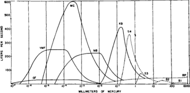
FIG. 7. Performance curves for typical pumps.
nozzle t o t h e wall since t h e mercury or oil vapor in diffusion p u m p s is generated in small boilers a t pressures of 1 m m . or less a n d expands after leaving t h e nozzle. However, mercury and certain oils can be vaporized under high pressure (1 t o 100 m m . of Hg) a n d ejected at high densities through nozzles a n d diffusers similar t o those in steam ejectors, and under these conditions the air m a y be entrained b y t h e ejector principle a n d passed into a fore v a c u u m of 0.5 t o 50 m m . (depending on the boiler pressure).
There are seven distinct classes of vapor jet pumps, depending on t h e operating fluid a n d t h e range of pressure covered:
(1) Steam ejectors, 760-1 m m . (2) Oil ejectors, 3 - 1 0 "2 m m .
(3) Oil booster pumps, 1 0 ^ - 5 X 10~5 m m .
(4) Semifractionating oil diffusion p u m p s , 10~2-5 "X 10~6 m m . (5) Fractionating oil diffusion pumps, 10~2-10~7 m m .
(6) Mercury p u m p s with ejector stages, 4 0 - 1 0- 7 m m . (7) Mercury diffusion pumps, 1 0_ 2- 1 0- 7 m m .
Figure 7 shows t h e performance curves for some typical p u m p s . Class (1) is illustrated b y one stage (SI), two stage (S2), three stage (S3), a n d four stage (S4) steam ejectors. T h e long low curve (RP) is typical
of a large rotary oil-sealed mechanical p u m p . T h e other curves repre
sent typical oil vapor p u m p s . Class (2) corresponds to K B , class (3) to M B , class (4) t o M C , and class (5) t o V M F and G F . Ordinary mer
cury diffusion pumps, class (7), with a liquid air t r a p would have a per
formance curve similar to t h a t marked G F .
M a n y analytical procedures require only a small oil-sealed mechanical p u m p a n d a cold t r a p t o keep t h e vapors of t h e sealing oil out of the system or t o keep water vapor out of t h e p u m p . However, rotary
p u m p s can seldom produce a v a c u u m below 0.001 m m . in a complicated system because their efficiency is very low at pressures under 0.1 m m . T h e y can easily produce t h e necessary fore vacuum for diffusion p u m p s and t h e latter are indispensable for reaching t h e low pressures required in t h e analytical procedures described in this chapter. Oil diffusion p u m p s are more convenient to operate t h a n mercury p u m p s because they do not require a cold t r a p to reach low pressures and t h e vapor is not poisonous. However, t h e oil vapor is sub
ject t o decomposition and contamination by foreign organic molecules, a n d only when employed in "fractionating p u m p s "
(115) can t h e oil be maintained sufficiently pure t o permit v a c u u m s of 10~6 m m . or less. Fractionation is accomplished b y partial condensation a n d refluxing and b y circulating t h e condensed oil through a series of boilers, see Fig. 9, so t h a t t h e u n w a n t e d volatile constituents will be ejected in t h e first boilers a n d t h e best oil is fed t o t h e last jet from whence only t h e least volatile vaporized fractions are exposed t o t h e v a c u u m system.
New p u m p fluids composed of certain silicone compounds are now avail
able which are claimed t o be less subject t o decomposition t h a n purely organic fluids (214).
8.2. Mercury Operated Pumps for Analytical Work
Mercury diffusion p u m p s with two or more stages (nozzles in series) capable of compressing a gas from 0.01 m m . or less u p t o 10 or 20 m m . of H g are t o be preferred for handling gases to be analyzed (Fig. 8).
FIG. 8. Mercury pump.
Oil diffusion p u m p s (Fig. 9) are excellent for producing a high v a c u u m without cold traps, b u t in general t h e y can not be used t o store t h e gas
FIG. 9. Two-stage fractionating oil diffusion pump. (Distillation Products, Inc.) by compressing it into reservoirs at pressures much above 1 m m . of H g because t h e required oil vapor t e m p e r a t u r e
would exceed t h e decomposition t e m p e r a t u r e at those pressures. T h e forepressure against which a diffusion p u m p will operate with full efficiency is in general about equal t o one half of t h e boiler pressure, and t h e latter can be estimated b y measuring t h e boiler t e m p e r a - t u r e a n d referring to the vapor pressure curves supplied b y t h e manufacturer of t h e p u m p fluid. T h e boiler pressure can be varied b y changing t h e heater input and is roughly a linear function of wattage.
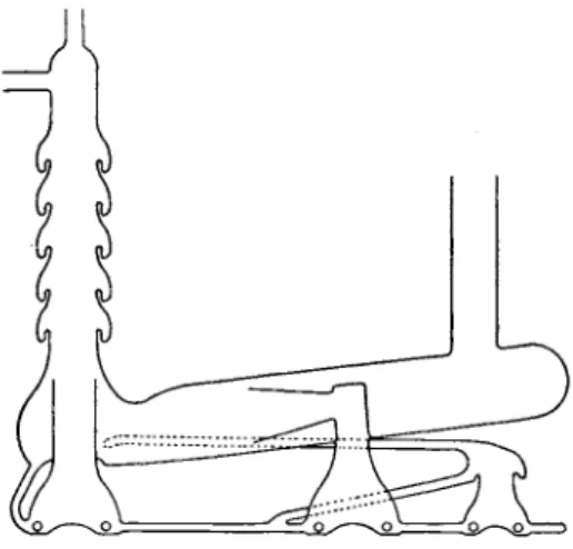
For very accurate q u a n t i t a t i v e transfer of a gas from one reservoir to another a Toepler p u m p , or various modifications described below, must be used. T h e Toepler p u m p can also be used to obtain a high v a c u u m b u t is seldom used for this purpose since t h e a d v e n t of high speed diffusion pumps. The only good q u a n t i - tative method of removing t h e whole of a gas sample for storage at atmospheric pressure is t h e use of a Toepler p u m p discharging through
a long vertical capillary t u b e extending under a bottle of mercury FIG. 10. Toepler pump
and collecting tube.
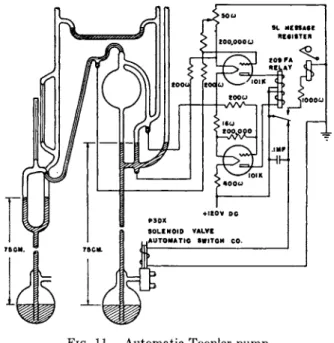
inverted in a dish of mercury (Fig. 10). An automatic Toepler p u m p and control circuit designed by Prescott and Morrison (32) is shown in Fig. 11. T h e mercury is lifted b y compressed air a d m i t t e d through a two-way solenoid valve t o t h e reservoir. W h e n t h e mercury overflows into the capillary at the top of t h e p u m p , the valve switches t h e reser
voir from the compressed air line to t h e atmosphere and the mercury
FIG. 11. Automatic Toepler pump.
falls. T h e valve is operated b y a polarized telegraph relay controlled b y a vacuum tube circuit and three contacts sealed into the p u m p .
8.8. Pumping Water Vapor
W a t e r vapor can be passed directly through an oil or mercury diffusion p u m p without spoiling the pumping action, b u t t h e water vapor is con
densed in a mechanical p u m p and after a short time enough will accumu
late in t h e oil used t o seal t h e p u m p s so t h a t the partial pressure of water vapor on t h e vacuum side can not be reduced below a few t e n t h s of a millimeter. Most types of diffusion p u m p discharging into a mechanical p u m p which has been saturated with water vapor will not operate effi
ciently since they usually require a forepressure of less t h a n 0.2 m m . Hence the water vapor should be condensed out by a dry ice t r a p placed between t h e diffusion p u m p and the mechanical p u m p .
3.4. Traps and Baffles
T r a p s are necessary on t h e high-vacuum side of mercury diffusion p u m p s when t h e presence of mercury vapor within t h e system is not desirable. A t r a p cooled by liquid air is necessary for pressures of 10~7 m m . or less. Although t h e vapor pressure of mercury a t dry-ice tem- peratures is about 10~9 mm., experience has shown t h a t pressures less t h a n 10~6 m m . are difficult t o achieve with dry-ice t r a p s designed to have low resistance t o gas flow. T h e t r a p m a y be partially filled with gold
J l
FIG. 12. Three types of cold traps.
foil or an alloy of one p a r t sodium t o two p a r t s potassium (94) which acts as a " g e t t e r " for mercury vapor. In general no t r a p is required with oil diffusion p u m p s since t h e vapor pressure of t h e common p u m p fluids is less t h a n 10~5 m m . H g at room temperature, and b y using a fractionating p u m p and a water cooled baffle pressures of t h e order of
10~7 m m . H g can be obtained with fluids such as Octoil-S without a cold t r a p . However, certain equipment, such as t h e mass spectrometer, m a y be sensitive t o traces of oil vapor and hence a cold t r a p should be used.
W i t h t h e aid of a dry-ice t r a p a v a c u u m of 10~4 m m . or less can be produced with a good rotary oil-sealed mechanical p u m p , b u t without a t r a p a pressure of 0.005 m m . or higher is usually indicated b y a Pirani gauge because of t h e vapor of t h e sealing oil. I t is not uncommon t o overlook t h e presence of this vapor when a McLeod gauge is t h e only manometer used. Dry-ice and acetone will cool a t r a p to about — 7 8 ° C , b u t it should be noted t h a t t h e vapor pressure of ice is about 10~3 m m . at this temperature. If pressures below 10~3 m m . are desired, t h e water vapor should be allowed to pass u n t r a p p e d through a diffusion p u m p or else trapped with liquid air. T r a p s m u s t be defrosted when it becomes evident t h a t t h e y are giving rise to " v i r t u a l l e a k s " (38).
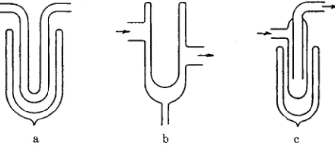
Three s t a n d a r d forms of cold t r a p are illustrated in Fig. 12a, b, and c.
T y p e a can be easily defrosted by lowering the Dewar flask and gently
flaming t h e U tube, b u t t o defrost t y p e b t h e refrigerant must be scooped or blown out of t h e reservoir, and t y p e c is even more troublesome since frost collected on the inner t u b e is only slowly removed b y flaming t h e outer tube, unless t h e pressure is allowed t o rise above 100 microns.
T y p e c is preferred when the vapor condenses to form a large q u a n t i t y of liquid at t h e b o t t o m of t h e t r a p .
For further information on cold traps, charcoal traps, and baffles consult references (1, 25, 35a, 38, 47a, 61, 129, 150, 151, 153, 195).
8.5. Assembly of Vacuum Systems
The assembly of t h e t y p e of v a c u u m system commonly used in analysis usually involves simple glass blowing such as t h e bending a n d joining of Pyrex glass tubes of less t h a n 20 m m . diameter. However, the system is often divided into units joined by s t a n d a r d taper or spherical ground glass joints, or b y t h e introduction of rubber tubing, tape, or gaskets. S t a n d a r d taper joints and stopcocks should be lapped together with a 900 mesh grit. Spherical joints are best sealed together with a thin film of v a c u u m wax (e.g., Apiezon W, Dekhotinsky, Picein, M y v a - wax). If grease is used, the joint should not be left unguarded overnight but should be protected with v a c u u m paint (glyptal) and always held together with the standard clamps for spherical joints. T h e silicone high-vacuum greases are recommended for stopcocks. Tests on stop
cocks rotated at intervals in a vacuum line have shown t h a t t h e greatest number of turns before "freezing" can be achieved with this t y p e of grease, and the viscosity is less affected by changes in temperature.
The vapors and occluded gas escaping from rubber and " v a c u u m "
grease are frequently t h e limiting factor in attaining a low pressure.
Wherever possible joints should be m a d e b y fusing t h e glass or using a good v a c u u m wax applied carefully t o avoid decomposition during melt
ing. F u r t h e r information on technique in making joints and seals is given in references (1, 6, 11, 12, 25, 38, 44, 85, 179, 181, 210).
3.6. The Flow of Gases through Vacuum Pipe Lines and Absorption Tubes The time required to evacuate t h e system and also t o transfer gas at low pressures from one part of t h e system t o another depends on the rate of flow of gases at low pressures through t h e connecting tubes and absorption tubes. At pressures below 1 m m . this rate of flow is usually the limiting factor because of t h e practice of using long narrow tubes whose conductance is much less t h a n t h e speed of t h e p u m p s a t these pressures. If the conductance of a t u b e is U and t h e p u m p speed is S0, then the net pumping speed available at t h e end of t h e connecting t u b e will be given by S in t h e formula
providing t h e p u m p speed, So, is measured under conditions consistent with t h e definition of U (75a).
T h e p u m p speed So is usually given in t h e manufacturer's catalog in terms of liters per second or cubic centimeters per second, or some other units of volume and time for all pressures in t h e operating range. T h e conductance U m a y be computed from t h e geometry of t h e tube, t h e mean pressure, a n d t h e physical properties of t h e gas (6, 60, 72, 128, 141).
C h a r t s are available* which will give t h e conductance of a n y cylindrical t u b e a t pressures u p t o t h e point at which t h e flow becomes turbulent.
T h e following table gives t h e approximate conductance in liters per second of 1-foot lengths (30 cm.) of small diameter tubing for various mean pressures of air at 25°C.
Inside diameter Mean pressure in mm. of Hg
in mm. 10"4 10"8 10"2 10"1 10° 10
4 0.026 0.026 0.025 0.038 0 17 1.5 6 0.083 0.083 0.080 0.14 0 80 7.3
8 0.19 0.19 0.19 0.38 2 5 23
10 0.37 0.37 0.37 0.86 5 8 54
18 2 . 2 2 . 1 2 . 4 7.7 60 570
T h e conductance of a t u b e of length L inches can be found b y multi
plying t h e values in t h e table b y 12/L. T h e conductance is approxi
mately constant until t h e product of t h e m e a n pressure in millimeters of H g a n d t h e diameter in millimeters exceeds 0.2 a n d t h e n increases rapidly as this product increases. W h e n this product is less t h a n 0.1, t h e mean- free-path of the air molecules is greater t h a n t h e diameter of t h e t u b e a n d the K n u d s e n "molecular flow" formula applies. This formula states t h a t t h e conductance is proportional t o t h e q u a n t i t y \/T/M where Τ is t h e absolute t e m p e r a t u r e a n d Μ is t h e molecular weight of t h e gas.
For air a t room temperatures t h e " m o l e c u l a r " conductance of a long t u b e in liters per second m a y be estimated b y dividing t h e cube of t h e radius in millimeters b y t h e length in millimeters. For short t u b e s
(length less t h a n ten times t h e diameter), such as t h e bore of a stopcock, t h e conductance is smaller because t h e m a x i m u m a d m i t t a n c e in liters per second of t h e end of t h e t u b e is limited t o 11.7 times t h e cross-section in square centimeters. This end correction is incorporated in t h e charts mentioned above according t o Clausing's formula.
* These are contained in a pamphlet on "The Flow of Gases through Vacuum Pipe Lines" which may be obtained from Distillation Products, Inc., Rochester, N.Y.
Charts are also available from Central Scientific Co., Chicago, 111. and National Research Corporation, Boston, Mass. Cf. J. Applied Phys. 17, 811 (1946).
K e n t y and Reuter (128a) have m a d e use of the fact t h a t molecular flow is proportional to \/T/M in the identification of residual inert gases during t h e analysis of t h e minute quantities of gas impurities occurring in certain v a c u u m tubes. If a gas of molecular weight Μ is isolated in a system of volume V which contains no surfaces capable of evolving an appreciable a m o u n t of gas at t h e given temperature, and the system is then opened t o t h e p u m p through a capillary whose conductance, U, is much smaller t h a n t h e p u m p speed or t h e conductance of a n y other p a r t of t h e system, then t h e pressure, p, will decrease with time, t} according to the formula (38)
ρ = Poe -u-toW/v
where p0, t h e initial pressure at time to, must be so small t h a t the flow through t h e capillary is molecular. The conductance, [ 7 , which in this case is also equal to the " s p e e d of exhaust," S, can be computed from
Γ , . * - . M I L ίο. (ζ)
providing p2 is more t h a n 20 times the " u l t i m a t e pressure'1 attainable in the system after pumping through the capillary for a very long time.
The speed of exhaust will remain constant as the pressure falls and can be correlated with the molecular weight, M, by Knudsen's formula for molecular conductance or by calibrating the system with a known gas.
T h e relative concentrations of two known gases can be determined by reference t o a calibration curve as shown by K e n t y and Reuter.
Absorption tubes packed with Ascarite, Anhydrone, copper oxide, etc. not only offer a high impedance to the flow of gases at low pressures but require a very long time for evacuating and outgassing. Accordingly t h e absorbent should be loosely packed granules not much smaller t h a n 20 mesh retained by loosely wadded plugs of glass wool. Complete absorption m a y be insured b y repeated circulation of t h e gas through the t u b e and hence a long densely packed t u b e is not needed. According t o Vacher and J o r d a n (39) a 2-inch column of 20 mesh Ascarite in a f-inch diameter t u b e will absorb a t least 0.2 g. carbon dioxide (100 ml. at N . T . P . ) .
3.7. The Circulation and Transfer of Gases with Diffusion Pumps and Toepler Pumps
T h e modern method is to circulate t h e gas through t h e absorption train with a mercury diffusion p u m p . N a u g h t o n and Uhlig (29) have designed a modified p u m p with an extra water-cooled member, labeled N U C in Fig. 8, which creates a sharp b o u n d a r y between t h e vapor jet and the gas in the fore vacuum so t h a t the gas can be compressed into a well-
defined volume independent of the variations in heater input. Details of this method are given in the section on t h e vacuum fusion a p p a r a t u s .
A circulating p u m p employing a rotating helical glass t u b e dipping in diffusion p u m p oil (or mercury) in a glass reservoir has been described by Harrington (110). The p u m p is driven b y a rotating electromagnetic field and is reversible. A constant-volume p u m p for circulating gases designed by Puddington (172) consists of two Toepler p u m p s connected in t a n d e m and alternately tipped b y a cam mechanism so t h a t t h e mer
cury oscillates between the p u m p s . An automatic Toepler p u m p involving an electrically operated valve for controlling t h e supply of compressed air for raising t h e mercury is described b y Williamson (216).
Other modifications of the Toepler p u m p will be found in references (6, 12, 123a, 173, 192). A simple method for t h e microanalysis of gases with dry reagents in which a combination Toepler p u m p and McLeod gauge is employed has been published by H a d e n and L u t t r o p p (108).
Puddington (171) has also described a scheme for collecting gases employ
ing a mercury diffusion p u m p and a long capillary t u b e in which the exhaust gas is entrained b y the condensed mercury on its way back t o the boiler of the p u m p . Beeck et al. (51) designed a small glass turbine with magnetic drive for circulating gas in a glass system during adsorption studies. Nickels (159) has also described a glass circulating p u m p for gases a n d liquids using mercury, and Simons et al. (185) developed an automatic gas circulating p u m p using oscillating columns of mercury.
3.8. Μercury Cut-Offs, Needle Valves, and Stopcocks
Valves for controlling the flow and isolating gases in a p p a r a t u s for analysis m a y be separated into six classes:
(a) Mercury cut-offs (1, 6, 12, 25, 37, 183a).
(b) Stopcocks lubricated with v a c u u m grease (1, 12, 25).
(c) Greaseless valves (12, 73, 202).
(d) Float or magnetic check valves (1, 25).
(e) Needle valves (12).
(f) Mercury controlled variable leaks (12, 50, 135, 178, 187).
Details of the construction and operation of individual types of valves in each class will be found in t h e references. Figure* 13 shows a typical mercury cut-off with float-valves as used b y Stock in his research on the boron hydrides. Figure 16 illustrates t h e use of several mercury cut-offs (at F, G, Η, I and L). T h e mercury m a y be raised and lowered b y any of the methods mentioned in Section 2.6 for operating McLeod gauges.
In designing a cut-off the length of the arms of the U must be greater t h a n the maximum possible pressure differential unless efficient float-valves
are used. Large-bore, hollow-plug glass stopcocks lapped with 900 mesh corundum and lubricated with Apiezon N , Myvacene-S (silicone high- vacuum grease), or other good vacuum grease, are now often used where mercury cut-offs were considered necessary a few years ago.
Most of the valves described in t h e references as well as large high vacuum valves, solenoid valves, special v a c u u m stopcocks, and v a c u u m grease can be obtained from the manufacturers of v a c u u m equipment previously listed (see foot
note, p . 344). Since valves and joints are two of the chief sources of trouble and contamination in a vacuum system, especially where rubber or a
" v a c u u m " grease is employed, considerable care should be given to t h e selection of suitable designs.
3.9. Manostats
A steady pressure m u s t sometimes be main
tained within specified limits of fluctuation as gas flows into a system and is either p u m p e d out or absorbed. A large n u m b e r of manostats have been described in the literature a n d while certain designs, such as t h e Cartesian M a n o s t a t * (104), are avail
able commercially, most of t h e m are home-made devices built for a special purpose and t h e reader must consult references (12, 25, 47, 66, 74, 81, 89, 92, 105, 109, 138, 139, 143, 160, 188, 196, 205) for designs which m a y suit his application. N o t e t h a t some of t h e earlier models, for example, t h e Bailey pressure regulator (47), were found t o have slight defects (bouncing) which were eliminated b y later workers (74). Attention is called t o t h e problem of variation in composition of a gas mixture flowing a t low pressures through a t u b e system and in particular t o t h e article b y Honig (119) on this problem as related t o t h e mass spectrometer.
3.10. Outgassing and Leak Hunting
Most laboratory equipment for analysis at low pressures is con
structed of glass, and pinholes in t h e glass or leaks through joints can be quickly detected with a high-voltage spark coil (leak detectorf).
Care must be taken, however, t o avoid puncturing t h e glass with strong
* American Technical Co., 532 Addison Street, Chicago 13, 111.; Emil Greiner Co., 161 Sixth Ave., New York, N.Y.
t Central Scientific Co., Chicago, 111.; W. M. Welch Scientific Co., Chicago, 111.
FIG. 1 3 . Mercury cut
off.
sparks (more t h a n 10 m m . in length) (2, 6, 38). Wherever possible t h e glass p a r t s t h a t m a y need leak testing should be supported on asbestos blocks well removed from a n y metal support which would draw t h e " l e a k d e t e c t o r " discharge away from t h e glass. Wood and felt supports can not be used if t h e glass is t o be outgassed by torching with a Bunsen flame.
Leaks in metal a p p a r a t u s (as well as glass apparatus) m a y be found by t h e following m e t h o d s :
(1) Helium plus t h e " M a s s Spectrometer Leak D e t e c t o r " (197, 220).
(2) Acetone, hydrogen, illuminating gas, etc. plus a Pirani gauge, ionization gauge, etc. (38, 137, 209, 155, 156).
(3) Soap solution or t u b of water plus compressed air (2).
(4) Sealing material (grease, glyptal, etc.) plus v a c u u m gauge (38).
(5) Freon gas plus copper-plate halide flame indicator (23).
(6) R a t e of rise of pressure in sections isolated b y valves, plugs, cover plates, etc. (2, 41).
Other methods have been used b u t these are the principle techniques, a n d t h e references m u s t be consulted for details and special methods.
T h e helium leak detector* is t h e most sensitive and quickest m e t h o d but t h e a p p a r a t u s is expensive t o install a n d maintain. M e t h o d (3) is commonly used for large leaks, m e t h o d (4) for porous areas a n d cracks in t e m p o r a r y set-ups, m e t h o d (6) for complicated systems with numerous joints, seams, a n d valves where leaks might occur, while m e t h o d (2) is t h e most common general procedure for small leaks a n d involves numerous variations in technique. I n particular under m e t h o d (2) t h e Pirani gauge, thermocouple gauge, glow-discharge tube, Alphatron, a n d Philips gauge m a y be used when t h e leak results in pressures from 10~3 t o 1 m m . (or higher) and t h e probe gas m a y be hydrogen, illuminat- ing gas (containing hydrogen, methane, etc.), carbon dioxide, methane, propane, helium, etc. or an organic liquid such as acetone, alcohol, ether, benzene, etc. m a y be brushed or sprayed over the suspected areas.
If t h e leak is so small t h a t t h e p u m p can maintain a pressure below 10~3 mm., t h e ionization gauge or t h e Philips gauge is used. W i t h t h e i o n gauge b o t h t h e collector current a n d t h e electron current (emission from hot filament) m a y fluctuate as t h e probe gas enters t h e leak. For example oxygen gas entering a leak will cause a decrease in t h e emission from t h e tungsten filament of an ion t u b e which is more easily detected t h a n a change in positive ion current (137, 156). Nelson (155) has
* Consolidated Engineering Corp., Pasadena, California; Distillation Products, Inc., Rochester, N.Y.; General Electric Co., Schenectady, N.Y.; National Research Corp., Boston, Massachusetts; Vacuum Electronic Engineering Corp., Brooklyn, N.Y.
developed a modification of this technique in which hydrogen entering t h e leak diffuses through a heated palladium tube* into an evacuated a n d sealed ionization gauge while other gases can not pass through t h e palladium.
" V i r t u a l l e a k s " m a y be caused by vapors from grease, rubber, mer
cury, or condensate in cold t r a p s and are most easily detected by com
paring a McLeod gauge reading with t h a t of a Pirani or other gauge which does not condense the vapors. T h e presence of vapor or occluded gas is also indicated by plotting the rate of rise of pressure and noting whether or not t h e slope of t h e curve decreases with time. W h e n t h e system contains a s a t u r a t e d vapor, t h e pressure (as indicated by a n y gauge except a McLeod) will usually rise or fall m u c h more rapidly with change in room temperature, or t h e t e m p e r a t u r e of a cold t r a p , t h a n would be indicated b y t h e perfect gas law ρ = nkT/v.
Leak hunting in a complex system should be systematic and in general begins with a check on t h e mechanical p u m p and t h e n proceeds back
wards toward t h e v a c u u m chamber, each section being isolated in turn, wherever possible, b y valves or cover plates. Provision for such testing should be m a d e when designing t h e system.
4 . T H E V A C U U M F U S I O N M E T H O D F O R T H E A N A L Y S I S O F G A S E O U S E L E M E N T S I N M E T A L S
4.1. History and General Principles
W h e n a steel sample is fused in a graphite crucible under v a c u u m at temperatures of 1 6 0 0 - 1 7 0 0 ° C . all oxygen-containing compounds are reduced to oxides of carbon, nitrides a n d hydrides are decomposed, and a n y dissolved gases are liberated. If t h e gases are removed quickly by a fast mercury diffusion p u m p a n d stored in a reservoir, t h e interference due t o manganese and aluminum vapors, which condense as active metal films on t h e colder p a r t s of t h e furnace and then reabsorb t h e gases, can be reduced to a minimum. T h e gases are then analyzed b y cir
culating through absorption t u b e s or t r a p s a n d noting t h e changes in pressure or the increase in weight of t h e absorption t u b e .
T h e present m e t h o d was developed b y J o r d a n ( 3 9 , 1 2 4 , 1 2 5 ) a n d his associates at the Bureau of S t a n d a r d s from 1 9 2 5 t o 1 9 3 1 . T h e history of t h e development from t h e original work of Walker a n d Patrick in 1 9 1 2 to the time ( 1 9 3 1 ) of J o r d a n ' s last article is summarized on pages 3 7 5 - 3 7 7 of reference ( 3 9 ) and additional references will be found in t h e footnotes on these pages. Subsequent improvements were m a d e b y
* A complete leak detector employing this principle is manufactured by the Radio Corporation of America, Harrison, New Jersey.
Chipman a n d F o n t a n a (4) in 1935 a n d b y N a u g h t o n a n d Uhlig (29) in 1943. Various means of simplifying the a p p a r a t u s and reducing the time required for determination of oxygen have been developed by Derge (76) and b y Alexander et al. (42).
N o s t a n d a r d procedure has been adopted for t h e v a c u u m fusion method and the literature on various modifications of t h e technique is already quite extensive. Complete details of t h e a p p a r a t u s a n d pro- cedures used in England have been appearing regularly in a series of reports b y t h e Oxygen Sub-Committee of t h e Joint C o m m i t t e e on t h e Heterogeneity of Steel Ingots, published b y the Iron a n d Steel I n s t i t u t e (28 Victoria Street, London).* Most of t h e developments in G e r m a n y appear in t h e Archiv fur das Eisenhuttenwesen in articles b y Hessenbruch a n d Oberhoffer (111), Diergarten (80), Meyer a n d Willems (146), Willems a n d co-workers (215). I n t h e United States numerous papers will be found in Metals Technology a n d t h e Transactions of the American Institute of Mining and Metallurgical Engineers as well as t h e Bureau of S t a n d a r d s publications a n d t h e Analytical Edition of Industrial and Engineering Chemistry (now Analytical Chemistry).
Oxygen has been t h e principal gaseous element of interest in steel analyses b u t hydrogen has also been t h e object of special study. Holm and T h o m p s o n (21) in 1941 recommended a low t e m p e r a t u r e (400- 800°C.) extraction m e t h o d instead of fusion for hydrogen. T h e y found t h a t t h e diffusion of oxygen a n d nitrogen through t h e solid steel is so slow t h a t all of t h e hydrogen can be extracted without m u c h contamina- tion from t h e other gases. However Moore (149) a n d his co-workers h a v e studied t h e r a t e of evolution of hydrogen as a function of tempera- t u r e a n d conclude t h a t t h e extraction is not always complete, even at
1000°C. A symposium on t h e determination of hydrogen in steel is reported in t h e Trans. Am. Inst. Mining Met. Engrs. (Jan. 1945) where a simplified fusion a p p a r a t u s for hydrogen is described b y Derge a n d co-workers (77). Carney, C h i p m a n a n d G r a n t (3a) h a v e described a
"tin-fusion m e t h o d " for the determination of hydrogen in steel in which t h e sample is dropped into a " l a k e " of molten tin at 1150°C.
4.2. Apparatus
A diagram of t h e a p p a r a t u s designed b y Vacher a n d J o r d a n is repro- duced in Fig. 14. C h i p m a n a n d F o n t a n a used a similar system b u t modified t h e furnace (A) t o include graphite radiation shields and a graphite " s p l a s h " plug. T h e y also chose t o introduce t h e samples b y suspending t h e m on a fine nickel wire wound on a stainless steel windlass rather t h a n using t h e Oberhoffer sample loading device (illustrated in
* First report 1937, 75 pages; second report 1939, 15 pages; third report 1941.
the article by Vacher and J o r d a n (39)). Alexander et al. (42) found t h a t t h e radiation shields and splash plug can be eliminated if t h e crucible is imbedded in graphite powder and a preliminary " l a k e " of molten metal is formed in t h e b o t t o m of t h e crucible before running t h e samples.
T h e crucible a n d sample are usually heated b y a high-frequency induction unit b u t Meyer and Willems (146) a n d Newell (158) have described graphite spiral furnaces (21, 22, 59). T h e induction unit
FIG. 1 4 . Vacuum fusion apparatus of Vacher and Jordan.
should have a capacity of about 30 k v a for fusion of 20-g. steel samples, about 20 kw being used to outgas the furnace during the blank while about 10-15 kw is sufficient to fuse the samples (22). However, only about 3 k v a is required for bringing the samples t o red heat (800°C.) in the extraction of hydrogen by the method of Holm a n d Thompson (21).
Alexander et al. (42) used a 5-kva (output) power oscillator a t 550 kc mean frequency for 5-g. steel samples.
T h e furnace t u b e is m a d e of fused silica with a wall thickness of 2 to 5 m m . T h e crucible, shields, and " s p a t t e r p l u g " (or t h e insulating powder) are turned (or filed) from Acheson graphite. T h e head piece is m a d e of brass or stainless steel and is sealed t o t h e furnace t u b e with a
vacuum wax, such as picein, Cenco Sealstix, M y v a w a x , or Apiezon W.
T h e connection t o t h e p u m p is usually located in t h e head a n d should be 20 m m . or more in diameter, if possible, similar to t h e t u b e used on Raine's carbon-spiral furnace (22) r a t h e r t h a n t h e narrow t u b e s illus
t r a t e d in the articles b y J o r d a n a n d b y Chipman a n d F o n t a n a (4). An optical pyrometer is used t o view t h e specimen through a small Pyrex glass window sealed in t h e head. Guldner and Beach (106a) have described an all-glass furnace.
T h e rest of t h e system is constructed of Pyrex glass,* although t h e mercury vapor p u m p m a y be of metal. T h e diffusion p u m p s should be equipped with t h e N a u g h t o n a n d Uhlig condenser (see Fig. 8) for pro
viding a sharp gas-vapor b o u n d a r y in t h e fore v a c u u m (29). T h e y m u s t be capable of compressing a b o u t 10 liter-millimeters (13 cc. at atmospheric pressure) of gas into t h e main reservoir. T h e general formula for storage of gas at room t e m p e r a t u r e (300°K.) is PV = 19000 m/M, where Ρ is t h e pressure in millimeters in t h e reservoir of volume V liters when filled with m grams of a gas having molecular weight Μ. T h u s if an 8-g.
sample contains 0 . 1 % oxygen, we m a y expect 0.014 g. CO for which Μ = 28 so t h a t PV = 9.5 liter-millimeters. Usually t h e gas evolved from a 10- t o 20-g. sample is less t h a n 10 liter-millimeters, a n d therefore if t h e mercury p u m p is capable of operating against a forepressure of 5 mm., or more, t h e volume of t h e reservoir m a y be about 2 liters.
Vacher a n d J o r d a n used a modified Stimson p u m p (191) capable of work
ing against a forepressure of 15 m m . T h e y found it advisable t o use only one 700-ml. reservoir when analyzing 20-g. samples, a larger volume unnecessarily increasing t h e time for clean-up of oxidized gases (39). I n cases where t h e gas evolution would m a k e t h e pressure in t h e reservoirs exceed t h e forepressure limit of t h e p u m p , t h e y recommend circulating t h e gases t h r o u g h t h e absorbents for short intervals without waiting t o complete t h e extraction from t h e furnace. This is possible only when t h e gravimetric procedure is used (39). C h i p m a n and F o n t a n a adopted t h e practice of removing p a r t of t h e stored gas, after reading t h e total storage pressure, b y passing it out through t h e mechanical fore p u m p a n d t h e n analyzing only t h e remainder in cases where considerably more gas was evolved t h a n expected (4).
T h e McLeod gauge is usually specially constructed for this work with three or more scale ranges. Vacher a n d J o r d a n used a gauge covering t h e range 20 t o 0.001 m m . I n general t h e gauge should cover t h e range from 0.0001 m m . t o slightly above t h e limiting forepressure a t which t h e diffusion p u m p breaks down. A Pirani gauge m a y be included if desired
* A complete Vacuum Fusion Apparatus is manufactured by Distillation Products, Inc., Rochester, N.Y.
to aid in leak hunting and t o give a continuous indication of t h e lower pressures, b u t the analysis should be done with the McLeod.
The analytical train consists of a reservoir with inlet t u b e reaching to the bottom, a U-tube filled with fresh copper oxide heated b y an electric furnace followed b y a tube containing anhydrous magnesium perchlorate (Anhydrone) or phosphorus pentoxide for absorbing water vapor, an absorption t u b e for carbon dioxide filled with sodium hydroxide on asbestos (Ascarite) backed by a drying agent such as Anhydrone, a mercury diffusion p u m p with N a u g h t o n and Uhlig condenser for circulat
ing the gases, and the McLeod gauge for measuring t h e pressure at t h e reservoir and other points in the train. Alexander et al. (42) prepared the cupric oxide reagent by impregnating porous beryllia fragments with saturated copper nitrate solution under vacuum and t h e n heating in a muffle furnace at 450°C. until evolution of nitrogen oxides ceased, reduc
ing t o copper by a stream of hydrogen at 350°C. and t h e n reoxidizing b y a stream of oxygen at 400°C. Stopcocks and connecting tubes are pro
vided so t h a t t h e gases can be circulated through any one of a n y com
bination of absorption tubes at will and so t h a t a n y p a r t of the train m a y be isolated, removed from the system, or evacuated b y the mechanical p u m p without disturbing the pressure in t h e rest of the system. T h e absorption tubes m a y be attached b y ground glass joints and in addition t o the large tubes used for m a n y consecutive runs b y t h e volumetric method a set of small absorption tubes with matching ground glass joints should be provided for checking t h e volumetric method b y t h e procedure of weighing the absorption t u b e on an analytical balance.
I n t h e volumetric method t h e storage p a r t of t h e system must be accurately calibrated while the diffusion p u m p is operating to determine the volume included b y the reservoir, the McLeod gauge (with mercury at t h e cut-off), and the connecting tubes t o the stopcocks and the bound
ary between vapor and gas in the forepressure end of the diffusion p u m p as determined b y t h e N a u g h t o n and Uhlig condenser. An estimate is first m a d e of this volume from the dimensions of the p a r t s involved. A known volume of purified nitrogen at atmospheric pressure is t h e n admitted from a calibrated burette. T h e pressure before and after admitting the nitrogen is read on the McLeod gauge, and t h e volume of t h e storage system is t h e n readily calculated (4). T h e total volume can also be easily determined if the volume of some p a r t of the system is accurately known, such as t h e volume of t h e reservoir t o t h e stopcocks, or the volume of t h e bulb and capillary of the McLeod. Nitrogen is trapped in the known volume after measuring the pressure and the rest of the storage system is then evacuated. T h e trapped nitrogen is then expanded into the whole storage system and the pressure measured again.