Navigation of Outdoor Mobile Robots with Extended Grid Algorithms
Cosmin MARCU, Levente TAMAS
Department of Automation Technical University of Cluj-Napoca
Cluj-Napoca, Romania
Cosmin.Marcu@aut.utcluj.ro, Levente.Tamas@aut.utcluj.ro
Abstract—Grid Locator systems describe locations anywhere in the world and are mainly used in radio communication to transmit stations location of the correspondents. This paper proposes to extend the use of Maidenhead Locator System to mobile robots navigation by transforming the GPS coordinates into higher precision extended grid squares. The experimental part of the paper was validated using real GPS data from a commercial drone. The data, as well as the source for the reproduction of the experimental part, is available at the homepage of the authors.
Keywords—grid mapping, navigation, mobile robots, locator systems, grid locator.
I. INTRODUCTION
The map creation and the map representation for an autonomous system is a key problem which is in the focus of the researchers from a long time [1]. One of the most popular mapping approaches for autonomous robotic systems is based on the grid mapping technique dating back to the 90’s [2]. This is a discrete representation of the topological maps, which are commonly obtained as an output of a mapping (emerging from a discrete sensor such as ultrasonic or LIDAR) step from an autonomous mobile system [3].
Although 3D grid representation exists for the surrounding environment[4], often due to their computational complexity instead the 2D grid cells are preferred. In order to construct these grid cell maps several techniques were developed focusing on the optimal representation of the free/occupied space in the map[2], smoothness of the navigation trajectories obtained using this type of map representation [5], as well as use-case specific implementation constraints related to the roughness of the terrain [6]. A good overview of the grid mapping techniques as well as benchmark of the different algorithms can be found in [1]. For the parameter tuning of grid mapping algorithms a good review can be found in [7].
Grid mapping systems are commonly used in military applications and in telecommunication. A well known system is MGRS – Military Grid Reference System and is used by NATO military for locating points on Earth [8]. The MGRS coordinates contain a grid zone designator, a 100000 square identifier and a numerical location. The precision of representation is up to 1 meter.
In radio communication, a commonly used grid mapping system is the Maidenhead grid locator. This system was
designed to facilitate the designation of geographical positions for use within the amateur radio community [9]. The system encodes the latitude and the longitude into pairs of symbols (letters and numbers), each lower pair representing higher precision rectangular areas containing the transformed GPS coordinate.
A fairly easy to use grid locator system for mobile robots navigation is the Maidenhead grid locator. In telecommunication, this grid locator system is mainly used with up to three pairs of encoded coordinates, which leads to a precision of about 4.5 Km in latitude and 6.3 Km in longitude.
For radio communication systems, this precision is accepted, considering that the locator is usually useful to approximate the distance between correspondents (which is, usually, hundreds or thousands of kilometers), or to determine the direction of the transmitter for antenna orientation adjustments. For mobile robots applications, a higher precision is needed, therefore, this paper proposes to extend the conversion of GPS coordinates to higher precision Maidenhead grid coordinates and use the obtained encoded coordinates in grid mapping navigation applications.
The current research is most similar to the one presented in [5] which introduces the coarse-to-fine constrained inverse distance transform based on Bezier splines smoothed with particle swarm optimization techniques. To best of our knowledge, the numerical representation of the coordinates was not addressed till now in the domain of grid mapping, hence this part of the paper contains the most prominent novelty in this work. The methods and the verification of the algorithms presented in this paper are based on the experimental and numerical data presented in [12].
II. MAIDENHEAD LOCATOR SYSTEM
The Maidenhead grid coordinates are mainly used in amateur radio communication to approximate the area where the transmitter is located (QTH locator). A QTH locator compresses the latitude and the longitude into string characters.
This technique eases the transmission of the location and makes it more readable, especially in continuous wave mode (Morse code).
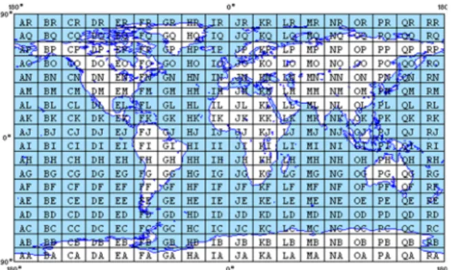
The compressed coordinates consist of pairs of letters and numbers. The first character in each pair represents the encoded longitude, while the second character represents the encoded latitude. The base of the first pair of characters is 18,
thus the globe is divided into 18 zones of longitude of 20 degrees each, and 18 zones of latitude of 10 degrees each.
These zones are encoded with letters from “A” to “R” (Fig.1).
The first pair of characters from the encoded coordinates is also called “field”.
The second pair of characters in the encoded coordinates uses base 10 and divides the previously encoded zones into squares. Each resulting square represents 1 degree of latitude and 2 degrees of longitude. The second pair of encoded coordinates is represented by numbers from “0” to “9”.
Additional precision can be added by subdividing the previous squares in base 24. The result is the encoded coordinates represented by a pair of letters from “A” to “X”, and square areas of 2.5 minutes of latitude and 5 minutes of longitude. Figure 2 presents an example of encoded coordinates for latitude of 48.147743 N and longitude of 11.628819 E.
In telecommunication, a fourth pair of encoded coordinates (resulting by continuing the encoding algorithm) is rarely used in very short communication spans. The fourth pair is also called extended square.
The Maidenhead locator is also used by amateur radio to approximate the distance between correspondents, especially during contests. The precision is higher if a larger number of characters pairs is used. For an encoding with three pairs of characters, the precision is about 4.63 Km in latitude and 9 Km in longitude, while for and encoding with five pairs of characters to a precision of about 20 m in latitude and 30 m in longitude.
III. EXTENDED GRID COORDINATES
Considering that continuing the algorithm for obtaining extended encoded Maidenhead coordinates would lead to a
higher precision, the resulting coordinates could be used for outdoor mobile robot’s navigation.
In mobile robotics, a commonly used method for path planning is the map segmentation [11]. On a known map, one can recursively apply successive division to obtain smaller areas which can be mapped as free or occupied zones. The occupied zones contain both obstacles and free space, while the free zones don’t contain obstacles. Usually, the path towards a target point is planned through the free zones of the obtained segmented map, taking into consideration that the robot should fit in the free zone. Therefore, the robot can navigate, theoretically, within free areas of minimum its dimensions.
In analogy with the result of the well-known segmentation method used for indoor navigation, one can apply custom segmentation methods on outdoor maps (i.e. satellite maps) to obtain free navigation zones. In outdoor navigation, we can use both GPS coordinates and satellite maps for path planning.
Anyway, navigation would be based on tracks – pairs of points (latitude and longitude). Reaching a target point would be influenced by GPS receiver accuracy which can be tens of meters, function of the number of satellites in contact with the receiver. In some cases, driving towards a certain point on the track would need information from other sensors.
In robotics, the positioning precision is a key point. The Maidenhead locator system used in telecommunication (with three pairs of encoded characters) cannot be used in outdoor mobile robots navigation, therefore the encoding algorithm should be continued for at least five or six pairs of encoded characters, which would lead to precision of about 2 meters in latitude and 3 meters in longitude.
The algorithm for converting the degrees of latitude and longitude into extended Maidenhead grid coordinates contains six steps, one for each pair of encoded characters. Considering that the goal is to divide the field square into smaller squares, at a certain point the algorithm can be applied recursively. For each pair in the encoded coordinates there is a predefined divider associated with the latitude and the longitude. The dividers depend on the numerical base used for each pair, and on the reminder obtained in the previous division, except for the first pair of encoded characters. The dividers list is presented in Table I.
TABLE I. DIVIDERS LIST
Pair index i
Longitude divider Di
Latitude divider di
Base Bi
1 20 10 18
2 2 1 10
3 0.083333 0.0416665 24
4 0.008333 0.004166 10
5 0.000347 0.000173 24
6 0.000034 0.000017 10
Starting with pair index 2, the base for even indexes is 10, while for odd indexes is 24. Knowing this, for indexes greater than 1, the formulae for dividers can be written as follows:
Fig. 1. Major fields of Maidenhead world grid map [10]
Fig. 2. Maidenhead encoded coordinates
= (1)
= (2)
To avoid negative numbers, the latitude is measured from the North to South between Poles and longitude is measured eastward from the antemeridian of Greenwich. This will give the first meridian a false east of 180 degrees and the equator a false north of 90 degrees. Therefore, the Western longitude coordinates will be subtracted for 180 and the Eastern longitudes will be added to 180. Also, the Southern latitude coordinates will be subtracted from 90 and the Northern latitude coordinates will be added to 90. After this correction, the newly obtained coordinated can be used for conversion to grid coordinates.
In the conversion algorithm, the following notations are used:
- Si – longitude symbol index for the pair “i”;
- si – latitude symbol index for the pair “i”;
- Ri – longitude reminder of the current division;
- ri – latitude reminder of the current division.
The symbol indexes for odd pairs start with zero for letter
“A” and end with 23 for letter “X”. For the even pairs of encoded coordinates, the symbol indexes are represented by numbers from 0 to 9.
The first pair of encoded coordinates is determined by dividing the corrected longitude and latitude by D1 and d1respectively. Therefore, denoting the corrected longitude with Lc and the corrected latitude with lc, the symbol indexes will be the integer part of the following divisions:
= (3)
= (4)
The remainders of the current division will be:
= − ∙ (5)
= − ∙ (6)
The second pair of encoded coordinates is obtained by dividing the reminders from the first step divisions (R1 and r1).
Therefore, the symbol indexes will be the integer part of the following divisions:
= (7)
= (8)
The remainders of the second step division will be:
= − ∙ (9)
= − ∙ (10)
Knowing that the dividers can be determined with (1) and (2), starting with the second step of the conversion algorithm, the equations (5)-(8) can be generalized as follows:
= (11)
= (12)
= − ∙ (13)
= − ∙ (14)
The equations (3)-(4) and (11)-(14) together with the dividers values presented in Table I can be used for fully convert longitude and latitude into a 6 pairs extended grid coordinates.
IV. APPLICATION OF EXTENDED GRID COORDINATES For demonstration purposes we proposed a mobile robot application in which key points on the robot track are converted into extended grid coordinates. Knowing the latitude and longitude of the initial point, target point and some intermediary points, the purpose of the conversions to extended grid coordinates is to identify the areas where the track should fit in, and also to determine if some heading corrections should be applied during navigation. The analysis
and representation of the track and coordinates is made on Google satellite map of the navigating area. Figure 3 presents the proposed track on the satellite map.
For the experimental validation we considered a real life outdoor scenario with GPS data acquired from an unmanned autonomous vehicle (UAV). Beside the GPS log [12], we collected camera images in order to filter out the spurious GPS readings due to the interferences of the signal with the buildings nearby the place where the experiments were performed. The Parrot ArDrone type UAV was equipped with a commercial GPS logger, measuring the GPS positions with an average of 5HZ frequency.
Fig. 3. Mobile robot track
The navigation direction of the drone was extracted from the front monocular camera of the drone fused with the IMU readings. For the purpose of this paper research, we have used in our algorithms only the GPS coordinates extracted from the UAV log.
The details regarding the image processing and pose estimation part can be found in our previous [13]. As guidance for the direction, the two lanes from the ground part were considered.
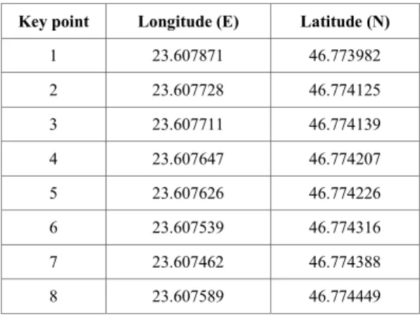
During the track recording of the drone, there were extracted 8 key coordinates. The first key point is the start point, and the last key point is the target point. The GPS coordinates of the key points are presented in Table II.
TABLE II. KEY POINTS COORDINATES
Key point Longitude (E) Latitude (N)
1 23.607871 46.773982
2 23.607728 46.774125
3 23.607711 46.774139
4 23.607647 46.774207
5 23.607626 46.774226
6 23.607539 46.774316
7 23.607462 46.774388
8 23.607589 46.774449
In the next step, the key point coordinates are transformed into extended grid coordinates. Therefore, equations (3)-(4) and (9)-(12) are applied for each key point in Table II.
The detailed result of the coordinate transformation for the first key point is presented in Table III, considering that the adjusted latitude is 136.773982, and the adjusted longitude is 203.607871 (90 degrees added for North latitude and 180 degrees added for East longitude).
TABLE III. KEY POINTS COORDINATES
Pair
index Si si Ri ri Pair
symbols
1 10 13 3.607871 6.773982 KN
2 1 6 1.607871 0.773982 16
3 19 18 0.024537 0023982 TS
4 2 5 0.007871 0.003148 25
5 22 18 0.000232 0.000023 WS
6 6 1 0.000023 0.000006 61
The resulting extended grid coordinate for the first key point is KN16TS25WS61.
Applying the same algorithm for the rest of the key points, the following extended grid coordinates are obtained:
TABLE IV. EXTENDED GRID COORDINATES
Key point Extended grid coordinate 1 KN16TS25WS61 2 KN16TS25WS29 3 KN16TS25WT20 4 KN16TS25WT04 5 KN16TS25VT95 6 KN16TS25VU70 7 KN16TS25VU44 8 KN16TS25VU88
From the obtained grid coordinates it is identified that the robot track is inside a 4-pair higher grid, KN16TS25, and passes through four 5-pairs lower grids: KN16TS25WS, KN16TS25WT, KN16TS25VT and KN16TS25VU.
The 5-pairs grids applied on the satellite map are presented in Figure 4.
Considering that our coordinates were converted into 6- pairs grid coordinates, each of the surfaces presented in Fig. 4 were divided into 10x10 sub-grids.
As a general rule, the resulted surfaces encoding is made from bottom to top for the latitude and from left to right for the longitude, ascending from “A” to “X” for the letter encoded pairs and ascending from “0” to “9” for the number encoded pairs. Knowing this rule is very useful in determining the navigation direction toward a point when applying driving techniques on the map based on encoded grids.
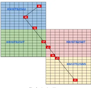
The last pair of our key point encoded coordinates are placed on the map as show in Fig. 5.
Fig. 4. 5-pair grid map
The track starts in sub-grid 61 of KN16TS25WS, passes through sub-grid 29 of the same grid, the crosses the two higher grids KN16TS25WT and KN16TS25VT and ends in sub-grid 88 of KN16TS25VU after a turn in sub-grid 54 of KN16TS25VU.
By simply overlaying the track over the 6-pair grid map, we can identify all the grids passed by the robot during its navigation.
V. GRID NAVIGATION METHODS
The navigation on the extended grid map can be different, function of the used input information. For simple applications like navigation towards a target point, the navigation depends on the bearing or heading angle. If the hardware system can determine/set the bearing and heading angle of the robot, then the driving strategy is simplified. Otherwise, the system has to be calibrated in order to approximate these, based on several input GPS coordinates.
Bearing is defined as direction or an angle between the meridian and the line connecting the target and the reference point. Heading is an angle or direction where the system is currently navigating in. Thus, for reaching a particular destination, the robot needs to adjust its heading direction with the bearing. The instrument which gives you the direction information for navigation is, generally, the compass.
A. Navigation with known bearing
Assuming that the robot can read the bearing information from the hardware equipment, in our particular application, the driving strategy is simplified and it’s fulfilled in two stages. First, the robot sets the orientation towards the 7th key point and starts travelling along the track. The second stage starts in the 7th key point by modifying the orientation towards the target point.
In this case, the grid map is used as feedback, together with the continuous reading from the GPS hardware. By converting the current GPS coordinates into extended grid coordinates and knowing the sub-grids containing the track
points, the robot can verify if its position is currently on the planned track. A deviation from the linear track is accepted as long as the position of the robot (GPS coordinate) is inside a grid square containing the track. The width of a 12 characters grid square is around 2 meters.
If the robot enters a grid which doesn’t contain planned track points, the orientation can be adjusted based on initial the direction of the robot and the differences between latitude or longitude of current grid and the target grid. For example, if the robot is heading North, and the current grid longitude has a lower value than the expected one, the robot should adjust the direction to right. If the longitude has a higher value than the expected one, then the adjustment has to be made with left turn (Fig. 6). For South heading, the adjustments will be made in opposite directions. The same strategy applies for West or East heading, but the inputs are taken from the latitude fields.
B. Navigation with unknown bearing
If the bearing information cannot be determined by the hardware equipment, then the robot should calibrate its direction before navigation start.
Assuming that the robot can travel with a constant speed and read the traveling time, the calibration procedure starts with a continuous read of the GPS coordinates and the purpose of finding the geographical North.
After identifying the extended grid coordinates of the current robot position, the robot should move and rotate into a pre-calibration position. This position is determined by moving backward until the previous grid is reached, then move forward at the limit of the current grid. If the grids differ in longitude, then the robot should rotate 90 degrees if current grid longitude is higher than the previous grid longitude or -90 degrees otherwise. If the grids differ in latitude, then the robot should rotate 180 degrees if current latitude is lower than the previous one, and should not rotate otherwise. The next steps in calibration procedure are the following:
- Start measuring time and travel forward until the next grid is reached;
- Restart timer and travel backward until previous grid is reached;
- Turn randomly (left or right) with a small angle and repeat the previous steps. If the running backward time Fig. 5. 6-pair grid map
Fig. 6. Grid based heading adjustment
from the second travel is higher than first traveling time, then robot should turn in the opposite direction and repeat steps 1 and 2;
- Repeat steps 1 and 2 until current travelling time is greater or equal than the previous one.
At the end of the above steps, the robot will be heading North. The next step is to identify the travelling time along the West-Est line. The procedure is the same as in the first two steps, but for left and right movement.
Considering that the calibration is made at a constant speed, after the calibration procedure we obtain the travelling time values along the latitude and longitude lines. The travelling time along the longitude will be greater than the traveling time along the latitude line. Therefore, the ratio between the longitude travelling time and the latitude traveling time will be the same as the distance ratio.
= = (15)
Where index “L” is related to longitude, while index ”l” is related to latitude. Equation (15) is to be applied only if time or distance parameters are greater than zero.
Considering that the robot is heading North after calibration, to identify the heading angle, the grid coordinates of the target point should be determined.
The heading angle is determined based on the target grid square projection on latitude and longitude. The number of grid squares from current grid to the projections of the target grid is used as distances to determine the heading angle. If we denote the heading angle with α, then:
∝= 90 − ∙ (16) In equation (16), “n” represents the number of grids along the latitude, “r” the ratio obtained with (15), and “N” the number of grids along the longitude. The heading angle shall be determined only if the number of grids (both along latitude and along longitude) is greater than zero. Considering that the tangent trigonometric function is not defined for ±90°, one should consider that the heading angle will never be exactly 0°
or 180°.
VI. CONCLUSION
The main purpose of our research was to identify if extended versions of currently known grid locator systems can be used in outdoor navigation strategies for mobile robots.
The extended version of the Maidenhead grid locator system provides valuable information for localization of the robot track points. Together with the satellite maps, the path planning algorithms can identify the obstacles on the track, and can provide navigation-safe areas information.
Another advantage of the extended grid locator is that, on small navigation maps, the encoded coordinate change happens only at the lower level pairs (5th or 6th pair). Thus, from the
software point of view, the amount of data transmitted or stored is low (2 or 4 bytes per coordinate, instead of full GPS coordinates). However, the grid coordinate determination is influenced by the stability of the GPS receiver. In some conditions, the accuracy can be low (up to 50 meters), function of the number of connected satellites or environmental conditions. Even so, if the application is permissive, one can apply the navigation algorithms on higher level grids.
ACKNOWLEDGMENT
This work was supported within ROCON research group at Technical University of Cluj-Napoca. The research was carried out within the financial support from PN-III-P1-1.1-TE-2016- 1265, and PN-III-P1-1.1-TE-2016-0670CNCS-UEFISCDI grants.
REFERENCES
[1] N. R. Sturtevant, “Benchmarks for Grid-Based Pathfinding,” IEEE Trans. Comput. Intell. AI Games, vol. 4, no. 2, pp. 144–148, Jun. 2012, doi: 10.1109/TCIAIG.2012.2197681.
[2] S. Thrun and A. Bü, “Integrating grid-based and topological maps for mobile robot navigation,” in Proceedings of the thirteenth national conference on Artificial intelligence - Volume 2, Portland, Oregon, 1996, pp. 944–950.
[3] K. Holmquist, O. Şenel, and M. Felsberg, “Computing a Collision-Free Path Using the Monogenic Scale Space,” in 2018 IEEE/RSJ International Conference on Intelligent Robots and Systems (IROS), 2018, pp. 8097–8102, doi: 10.1109/IROS.2018.8593583.
[4] A. Hornung, K. M. Wurm, M. Bennewitz, C. Stachniss, and W. Burgard,
“OctoMap: an efficient probabilistic 3D mapping framework based on octrees,” Auton. Robots, vol. 34, no. 3, pp. 189–206, Apr. 2013, doi:
10.1007/s10514-012-9321-0.
[5] T.-K. Lee, S.-H. Baek, Y.-H. Choi, and S.-Y. Oh, “Smooth coverage path planning and control of mobile robots based on high-resolution grid map representation,” Robot. Auton. Syst., vol. 59, no. 10, pp. 801–812, Oct. 2011, doi: 10.1016/j.robot.2011.06.002.
[6] P. Fankhauser and M. Hutter, “A Universal Grid Map Library:
Implementation and Use Case for Rough Terrain Navigation,” in Robot Operating System (ROS): The Complete Reference (Volume 1), A.
Koubaa, Ed. Cham: Springer International Publishing, 2016, pp. 99–120.
[7] “A quantitative study of tuning ROS gmapping parameters and their effect on performing indoor 2D SLAM - IEEE Conference Publication.”
[Online]. Available:
https://ieeexplore.ieee.org/abstract/document/7847825. [Accessed: 05- Feb-2020].
[8] L. Letham, “GPS Made Easy: Using Global Positioning Systems in the Outdoors”, Mountaineer, 1995, ISBN 978-089-886-4649
[9] P. Nag, S. Sengupta, “Introduction to Geographical Information System, Concept Publishging Company, New Dehly, 2008, ISBN 8180694339 [10] “QTH Locator Droid – Mobile App”, [Online], Available:
qrznow.com/qth-locator-droid-mobile-app, [Accessed: 05-Feb-2020]
[11] A. Siadat, A. Kaske, S. Klausmann, M. Dufaut, R. Husson, “An Optimized Segmentation Method for a 2D Laser-Scaner Applied to Mobile Robot Navigation”, IFAC Proceedings Volumes, vol. 30, Issue 7, 1997, ISSN 1474-6670
[12] “Robotics and Nonlinear Control”, [Online], Available:
http://rocon.utcluj.ro, [Accessed: 05-Feb-2020]
[13] E. Páll, L. Tamás, and L. Buşoniu, “Vision-Based Quadcopter Navigation in Structured Environments,” in Handling Uncertainty and Networked Structure in Robot Control, Springer, 2015, pp. 265–290.