BIO-INSPIRED LOW-COST ROBOTIC JOINT WITH REDUCED LEVEL OF BACKLASH
AND A NOVEL APPROACH: THE EMULATED ELASTIC ACTUATOR
J´ozsef Veres
Faculty of Information Technology P´azm´any P´eter Catholic University
Scientific adviser:
Gy¨orgy Cserey, Ph.D.
A thesis submitted for the degree of Doctor of Philosophy (Ph.D)
2013
DOI:10.15774/PPKE.ITK.2013.003
I would like to dedicate this thesis to my loving family ...
DOI:10.15774/PPKE.ITK.2013.003
Acknowledgements
First of all, I would like to thank my supervisor Gy¨orgy Cserey for in- troducing me to scientific work and for his constant support in bringing our ideas into reality and believing in my research activity. I am thank- ful for the P´azm´any P´eter Catholic University Faculty of Information Technology and the Multidisciplinary Doctoral School for providing tools and a caring environment for my work, especially personally for Judit Ny´ekyn´e-Gaizler, Tam´as Roska and P´eter Szolgay. I would like to thank to my closest colleague ´Akos Tar for the long-lasting joint work during these years. The cooperation of my colleagues at the Robotics Laboratory Norbert S´ark´any, ´Ad´am R´ak, Norbert H´oz, Bal´azs J´akli, Gergely So´os, Alp´ar S´andor and Ferenc Lombai is greatly acknowl- edged. The work with them greatly contributed to my scientific re- sults. I would like to thank also my fellow PhD students and friends for their help, especially to D´avid Tisza, P´eter Vizi, J´anos Rudan, Zolt´an Tuza, D´aniel Szolgay, Andr´as Kiss, G´abor Tornai, L´aszl´o F¨uredi, Zolt´an K´ar´asz, Andrea Kov´acs, Vilmos Szab´o, K´alm´an Tornai, Bal´azs Varga, Tam´as Pilissy, R´obert Tibold, ´Ad´am Balogh and Endre L´aszl´o.
Thanks especially for the discussions and ideas to G´abor Szederk´enyi, Andr´as Ol´ah, Attila Kis, G´abor V´as´arhelyi, Krist´of Iv´an, ´Eva Bank´o, B´ela Weiss, Krist´of Karacs and Attila Tihanyi. Special credits are also for the endless patience and helpfulness to Mrs Vida, L´ıvia Adorj´an, Mrs Haraszti, Mrs K¨ormendy, Mrs Tihanyi and Mrs Mikesy and the rest of administrative and financial personnel. The Operational Pro- gram for Economic Competitiveness (GVOP KMA), The office of Naval Research (ONR) and the Hiteles Ember Foundation for their support are greatfully acknowledged. Special thanks go to Sarolta Tar, Mikl´os Gy¨ongy and Zs´ofia Cserey who helped a lot in the English revision of the text.
The loving support of all my family and my fianc´ee Zs´ofia helped me through the hardest moments of this period.
List of Figures
1.1 Biped robot (single support phase) . . . 12
2.1 Electromechanical model. . . 21
2.2 Photo of the implemented prototype. . . 22
2.3 Normalized static torque characteristic of the stepper motor. . . . 23
2.4 Illustration of the backlash . . . 24
2.5 Piecewise linear function for backlash modelling. . . 25
2.6 Flowchart of the closed-loop commutation. . . 28
2.7 Block diagram of the motion control of the joint. . . 29
2.8 Results of the model validation. . . 30
2.9 Simulation results of the standard case. . . 31
2.10 Experimental results of the standard case. . . 32
2.11 Simulation results of the Flexor-Extensor case. . . 33
2.12 Experimental results of the Flexor-Extensor case. . . 34
2.13 Implemented 11 DOF biped robot. . . 36
3.1 Comparison of different off-the-shelf electric motors. . . 43
3.2 A hybrid stepper motor with local controller. . . 45
3.3 Block diagram of the electronic commutation. . . 46
3.4 This figure shows the instantaneous torque produced by the two phases being energized at the rated current. . . 48
3.5 Equivalent circuit of phase A of the stepper motor. . . 49
3.6 Free acceleration due to constant torque (iA versusiAref).. . . 51
3.7 Schematic of the layout for the linear elastic behavior’s emulation. . 52
3.8 Simulation of the Hooke type elastic behavior . . . 53
3.9 Experimental result of the Hooke type elastic behavior . . . 54
3.10 Experimental result of the Hooke type elastic behavior with com- pensation . . . 54
DOI:10.15774/PPKE.ITK.2013.003
3.11 Kelvin-Voight type of elastic behavior with high level of viscousity (η= 1.5×10⁻³ N m s / rad). . . 55 3.12 Damped harmonic oscillation with k= 178 Nm/rad and η =B. . . 56 3.13 Example for negative damping (η =−1.28×10⁻³ N m s / rad). . . 57 3.14 Leg modeled as linear spring attached between the center of mass
of the body and the contacting point on the ground. . . 58 3.15 2D kinematic description of the proposed one legged robot. . . 59 3.16 Non-linear force-distance characteristic Fv(y2) of the resulting vir-
tual spring in case of the linear torsional elasticity. . . 60 3.17 Non-linear torque-deflection characteristicτns(θ) of the joint elastic-
ity intended to realize the desired linear virtual spring. . . 61 3.18 One legged robot with two degree-of-freedom. . . 64 3.19 Simulation and experimental result of the non-linear elastic behavior
that realize the linear virtual spring . . . 65 3.20 Positional accuracy of a 11 vs 15-bit sensor. . . 67 3.21 Percentage of the loss in torque versus commutation latency. . . 68 3.22 Current settling over the two supply voltages (V1=6.11V andV2=12V) 69 3.23 Maximum available angular speed as a function of the supply voltage. 70 3.24 Maximum available angular speed versus the magnitude of the current. 71 1 Schematic of the Emulated Elastic Actuator’s electronics. . . 86
List of Tables
2.1 Comparison of the results . . . 35 1 List of constants . . . 85
DOI:10.15774/PPKE.ITK.2013.003
Summary of Abbreviations
Abbreviation Concept
PMSM Permanent Magnet Stepper Motor
HSM Hybrid Stepper Motor
SEA Series Elastic Actuator VSA Variable Stiffness Actuator FIR Finite Impulse Response DAC Digital to Analog Converter ADC Analog to Digital Converter SPI Serial Peripheral Interface
PC Personal Computer
DOF Degree Of Freedom
PCB Printed Circuit Board
LUT Look Up Table
MSB Most Significant Bit
LSB Least Significant Bit
CAD Computer Aided Design
Abbreviation Concept
PWM Pulse Width Modulation
COM Center Of Mass
EOM Equation of Motion
CPR Counts Per Revolution
GRF Ground Reaction Force
EMI ElectroMagnetic Interference
DOI:10.15774/PPKE.ITK.2013.003
Contents
Acknowledgement i
List of Figures iii
List of Tables v
Summary of Abbreviations vi
Contents viii
1 Introduction 10
1.1 Motivations . . . 11
1.2 Bipedal robots . . . 11
1.3 Goals of the dissertation . . . 13
1.4 Framework of the dissertation . . . 14
2 Bio-Inspired Low-Cost Robotic Joint with Reduced Level of Back- lash 16 Nomenclature . . . 17
2.1 Introduction . . . 18
2.2 The inspiring human flexor-extensor mechanism . . . 19
2.3 Description of the proposed robotic joint . . . 20
2.4 Modeling of the joint . . . 22
2.4.1 Stepper motor model . . . 22
2.4.2 Gear train and backlash model . . . 24
2.4.3 Complete model . . . 26
2.5 Motion control . . . 27
2.6 Simulation and experimental results . . . 29
2.7 Conclusion . . . 35
CONTENTS
3 A novel concept: The Emulated Elastic Actuator 37
Nomenclature . . . 38
3.1 Introduction . . . 40
3.2 Concept of the Emulated Elastic Actuator . . . 45
3.3 Model of the hybrid stepper motor . . . 48
3.4 Linear type elasticity: Hooke and Kelvin-Voight model . . . 52
3.4.1 Positive damping . . . 56
3.4.2 Negative damping . . . 57
3.5 Non-linear type elastic behavior for legged robots . . . 58
3.5.1 Underactuated, one legged robot with two degree-of-freedom 59 3.5.2 Euler-Lagrange method based formalization of the dynamics 62 3.5.3 Simulation and experimental result . . . 64
3.6 Analysis of the limiting factors . . . 66
3.6.1 Position . . . 66
3.6.2 Speed . . . 67
3.6.3 Acceleration . . . 71
4 Summary 72 4.1 Main findings and results . . . 73
4.2 New scientific results . . . 73
4.3 Application of the results . . . 75
The author’s publications 77
References 79
Appendix 85
DOI:10.15774/PPKE.ITK.2013.003
Chapter 1
Introduction
1. INTRODUCTION
1.1 Motivations
Walking on two legs, or bipedalism, is the capability of just a few species on the globe. Strictly speaking, only the primates are able to walk like us. Even for a human takes years to acquire the ability of stable walking. Thus, not surprisingly, the area of biped walking robots is one of the most researched fields of robotics.
For almost the whole 20th century, creating biped robots that feature balancing was a very difficult task to accomplish. As a result, robotic locomotion were mainly limited to wheeled or multi-legged solutions. After the first revolution of electronics, that introduced the mass of cheap microprocessors, building of a two-legged robot that maintains its postural stability became feasible. During that period of time, Japan had almost no competitor. Researchers at Waseda University [1] are thought as the pioneers of biped walking robots. In 1986, Honda Inc. started a large-scale research on biped robots to construct and commercialize full-size humanoid robots. The goal was to create human-like robots that would be capable of assisting elderly, or performing tasks that are dangerous to humans.
After fifteen years of extensive research, whereof the first seven prototypes out of ten had only legs without upper body, ASIMO [2] the most famous humanoid walking robot has been introduced. The child-size robot could walk, run, turn, climb stairs, grasp objects and interact with its environment. Despite all the success, the vision of biped robots assisting us, has still not yet been achieved.
One of the reasons for that is the lack of appropriate actuation mechanism that prevents us to successfully mimic the human locomotion in everyday situations. In this dissertation I will attempt to face that issue of biped walking robots.
1.2 Biped robots
Biped robots is a subclass of legged robots. Since, a complete humanoid robot must have two legs, therefore all humanoid robots can be thought as biped robots.
However, a biped robot do not necessarily have arms and head. Strictly speaking, a biped is an open kinematic chain with two sub-chains that are the legs. In almost all the cases, there is an extra sub-chain connected to the center point of the hip, the torso that mimics the upper body.
Fig. 1.1 illustrates the single support phase where only one leg touches the ground at a time. The leg that is in contact with the ground called the stance leg and the other one is the swing leg. In this phase the robot is underactuated
DOI:10.15774/PPKE.ITK.2013.003
Figure 1.1: Biped robot (single support phase)
since there is no direct control over the tipping. Similarly, there is the double support phase where both legs are in contact with the ground and the robot is overactuated.
Walking can be thought as the alternating phases of single and double support.
The difference between running and walking is the presence of flight phase where both legs are in the air for a short period. To simplify the non-trivial problem of walking often planar bipeds are used that, in contrast to the full three-dimensional ones, can only move in the sagittal plane.
The simplest gait is the statically stable gait where the robot’s center of mass (COM) is always within the support polygon of the feet. That means, at any point of the gait the robot could be stopped and it does not tip over. In contrast, there is dynamically stable gait. Despite the fact that it produces a stable walking while the robot is in motion, the gait could not be stopped at any time without the risk of tipping over. The reason for that is the dynamically stable gait allows the biped’s center of pressure (CoP) to be on the boundary of the support polygon [3].
Strictly speaking, in this case CoP is the point on the ground where the resultant of the ground-reaction force acts. In the literature of this field the term of the Zero Moment Point (ZMP) is often used instead of the CoP. The criterion of ZMP was originally defined by Vukobratovic et al. in 1972 and become the most widely used method to control the bipeds locomotion to be always dynamically stable [4].
It is important to note that, however, the ZMP criterion is an effective and rel-
1. INTRODUCTION
atively easily be implemented technique, it features extremely low energy efficiency compared to human walkers. The main reason for that is the high feedback gains required to maintain local stability. The high feedback gains often cause unwanted active braking of the actuators resulting unnecessary negative work. Furthermore, it requires good power transmission to avoid oscillation, that increase the cost of the robot.
In addition to the statically and dynamically stable walking, there is a rela- tively new approach, the limit cycle walking [5]. The limit cycle walking could be defined as a normally periodic sequence of steps that is globally stable but not locally stable at all the time. Normally periodic sequence of steps means that the required walking is the exactly same closed trajectory repeating in state space. In contrast to the conventional trajectory control, where all the points on the trajec- tory needs to attract their local neighborhood in the state space, in this case it can be relaxed. The reason for that is the neighboring trajectories can approach the nominal trajectory over multiple steps. This is often called the cyclic stability.
Unfortunately, the detailed description of the gait synthesis is beyond the scope of the dissertation.
There are three major challenges associated with biped robots [6]. The first one is the limb coordination. Obviously, the ultimate goal of walking is to move the COM of the biped robot from point A to point B that is a low degree of freedom (DOF) task. Since these robots are having high DOF, it can be easily seen that the task of walking does not uniquely specify how the coordination of the limbs must be done. From the many solution, finding one can be a challenge, especially finding the optimum.
The second one is the hybrid dynamics. At the end of the swing or single support phases there are always impacts occur at the instance of the touch down.
According to this, the model must have multiple phases that means the model is hybrid. The control of hybrid systems is challenging.
The third difficulty is the underactuation. In contrast to the industrial manip- ulators, that are fixed to the ground and fully actuated, legged robots are usually underactuated. It means, there are DOFs of the system that cannot be directly controlled. Non-direct control of an underactuated system (for example through inertial coupling) is hard to achieve.
DOI:10.15774/PPKE.ITK.2013.003
1.3 Goals of the dissertation
Research on biped robots is important for two reasons. On one hand to create walking robots that are able to assist the humanity. For example, in case of a catastrophe of a nuclear plant, that unfortunately lately happened at Japan’s Fukushima Daiich, biped robot could be deployed to save human lives. On the other hand, research on biped robots could help us to better understand human locomotion disorders, for example locomotor rehabilitation for individuals with stroke, or how to improve lower-limb prostheses.
High-end humanoid biped platforms are extremely expensive. There are a few low-end commercially available two-legged robots, like the NAO from the Alde- baran Robotics, that are used in academic research. These robots are usually incor- porating robotic joints made of standard parts. In terms of actuators, fabrication inaccuracy introduces significant mechanical backlash which is a hard-nonliearity from the control point of view.
Therefore, during my early research I tried to address the issue of non-linearities in the actuators of biped robots by attempting to create a bio-inspired low-cost robotic joint using PMSMs and low-level active control.
In addition to nonlinear phenomena, walking inherently implies dynamics that are not necessarily been addressed by the theory of classical robotics. In contrast to the industrial robots, walking, running or climbing stairs with a two-legged robot requires substantially different approaches.
A new field of robotics is emerging namely thedynamic walking. In 2006, a new international conference has established to allow researchers all over the world to share their findings. The central issues are the energy efficiency, dynamic stability and complaint actuation. Compliance is turned to be essential for the fundamental interaction with the environment. During the half-year, while I had the privilege to get involved in the research of James Schmiedeler’s group at the Locomotion And Biomechanics Laboratory (Notre Dame), I understood the limits of the principles of classical robotics. After my returning to Hungary, I started to work on a novel concept that could improve the dynamics of biped robots.
Thus, during my late research I tried to investigate a new type of robotic actuator that can emulate the different kind of elasticity under software control or in other words, to be able to implement intrinsic compliance that is found to be crucial for dynamic movements.
1. INTRODUCTION
With this new concept, unlike existing mechanical solutions, like SEA [7] that are limited to fixed elastic behaviour, change in the parameters of the elasticity could become available on the fly. Considering the fact that the springiness would being emulated in software, exotic non-linear functions would become realizable.
1.4 Framework of the dissertation
In Chapter 2, a bio-inspired low-cost robotic joint is proposed that is based on PMSMs. The ability of reduction in the level of backlash under active control is investigated. The numerical results acquired through simulations, and experi- ments are discussed and then compared to the standard robotic joint configuration.
In Chapter 3, a novel concept is introduced namely the software controlled em- ulation of physical elasticity of a robotic joint. Not only the concept, but also the hardware implementation is presented along with simulations and experiments that support the functionality of the actuator.
In Chapter 4, the methods and the new scientific results of the dissertation are summarized. Finally, the possible applications are highlighted.
DOI:10.15774/PPKE.ITK.2013.003
Chapter 2
Bio-Inspired Low-Cost Robotic Joint with Reduced Level of
Backlash
Nomenclature
b Measure of a backlash as a distance [m]
β Measure of a backlash as an angle [rad]
r Radius of a gear [m]
τ Torque [Nm]
i Current [A]
I Nominal current [A]
θ Angle [rad]
J Inertia [kg m2]
B Viscous friction [Nms/rad]
F Force [N]
ω Angular velocity [rad/s]
n Gear ratio N Pole number x Linear position [m]
k Feedback strength [1/s]
K Stiffness [N/m]
e Angle difference [rad]
E Angle difference treshold [rad]
T Time period [s]
Subscripts
m Motor
a,b Phase a and b p Pole
g Intermediate gear l Load (real) L Load (estimated) r Reaction
d Desired
c Computed
t Total
DOI:10.15774/PPKE.ITK.2013.003
2.1 Introduction
Most robotic joints are actuated by rotational mechanisms. Typically, these mech- anisms are driven by electric motors whose operating speed is higher than what the joints actually require. Gearboxes are then used to reduce the speed of the joints and also to increase their torque. The incorporation of a gearbox corrupts the continuity of the torque transmission in most cases because of the backlash phenomenon. Backlash originates from the gear play that results from the imper- fectness of the fabrication or the increased wear level of the mating gears. During static motion this introduces only positioning errors but in dynamic cases limit- cycles may occur. Some mechanical and control solutions that reduce the effect of backlash are given below.
Starting with the control solutions it can be concluded that numerous pub- lications are available in the field. Most of these papers offer solutions for the modeling and identification of the mechanical system together with the backlash phenomenon [8, 9, 10, 11, 12, 13]. Different approaches include vibration anal- ysis [14], wavelet analysis [15], utilizing fuzzy logic [16] and Kalman filters [17].
Compensation of the effect of the backlash using Stribeck friction was reported in [18] and [19]. Controllers and adaptive controllers for mechanical systems with backlash can be found in [20, 21, 22]. There are papers focusing on different ap- plications like positioning [23] or target tracking [24]. Hovland et al. [25] showed a backlash identification in robot transmission. Backlash compensation for a hu- manoid robot with a disturbance observer [26], as well as with a genetic algorithm [27], were reported. Turning now to mechanical solutions, a few examples include anti-backlash gears, pre-loaded gears, and harmonic drives. The latter were origi- nally developed for aerospace and military applications and offer a very low level of backlash with high reduction ratios in a compact size. These advantages have made the harmonic drive the most widely used robotic gear type. The disadvan- tages of using this type of mechanical solution are its increased level of elasticity and its significantly higher cost.
The cost of the actuator can be an issue, for example in the cases where high degree of freedom (DOF) robots are needed. Good examples for this issue are the humanoid or biped robots where tens of joints are usually required to be actuated.
In almost all cases these are series manipulators. According to Akhter et al. [28]
a large percent of these robots are not equipped with harmonic drives but use standard gears presumably to be more cost effective but at the same time suffering
2. BIO-INSPIRED LOW-COST ROBOTIC JOINT WITH REDUCED LEVEL OF BACKLASH
from the effect of backlash.
In this chapter, a low-cost alternative solution for decreasing the effect of back- lash in robotic joints will be presented. The proposed solution reduces backlash by incorporating a flexor-extensor pair of low-cost PM stepper motors bundled with low-end integrated gearboxes. The method was inspired by the biological struc- ture of human limbs, which inspiration will be briefly introduced in the following section.
There are related studies in the literature. For parallel manipulators Sven et al.
[29] and Boudreau et al. [30] have recently published their dual motor mechanism that can be used to reduce the level of backlash. The original level was reported to be reduced by over 90%. Turning to the series manipulators, which is only in the scope of this work, Kiyoshi et al. [31, 32] presented their twin-drive mechanism that is related to the solution of this work. They were using direct-drive DC motors, which creates a significant limitation since without gears the robots that are in the scope of this work could not be built due to the lack of the adequate torque capability.
It has to be emphasized that this approach does not target the area of the classical industrial manipulators — where precision and repeatability are more important than the cost of the actuators — but the robots with high DOF that require negligible backlash at low-cost.
2.2 The inspiring human flexor-extensor mecha- nism
Human muscles can only exert force in one direction. This is why it is always necessary to have counterparts to be able to create repetitive motion with the help of cyclic contractions, like walking. These muscle groups are called the agonists and the antagonists. Well known examples are the biceps brachii and triceps brachii muscles of the upper arm. By using these antagonistic pairs we are able to perform a wide variety of motions. For example, if the two antagonistic muscles are contracted simultaneously, it is possible to change the stiffness of the joint.
In terms of precise co-ordination of these muscle groups, complex neural controls are generally required. However, simple reflex-arcs exist that can realize fast but very simple reactions. A good example for that is the collateral inhibition of the antagonistic muscles that serves as a basic mechanism of muscle co-operation. This
DOI:10.15774/PPKE.ITK.2013.003
idea inspired me to design and implement an alternative solution for the backlash problem of low-cost robotic joints.
My approach is to use a pair of low-cost actuators instead of a more expensive solution that contains a harmonic drive. Then one actuator will be dedicated for the right turn and the other for the left turn like flexing and extending in the human limbs. A smooth motion can be realized with a proper control by mimicking a simple reciprocal innervation of the two muscle groups. The main advantage of this approach is that the backlash of the joint can be almost completely eliminated with a simple digital control that is implemented using a low-end microcontroller.
2.3 Description of the proposed robotic joint
As it was introduced in the previous sections this approach uses a pair of actuators.
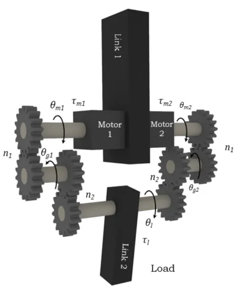
These include gearboxes with a significant level of backlash. Fig. 2.1 shows the structure of the proposed joint. The two actuators that are facing in an opposite direction are attached to a fixed body (Link 1). The outputs of the gearbox axes are directly coupled with the output of the robotic joint that is actuated (Link 2). The following convention will be used: Motor 1 is assigned to the right turn (flexing) and Motor 2 for the left turn (extending). This could be arbitrarily set but the above written convention will be used. The gearboxes are low-end spur type and are integrated with the PM stepper motors. These are three stage gearboxes with a gear reduction ratio of 100:1 (n1 =n2 = 10). The total backlash (βt) of the individual gearboxes is 0.0192 rad. Nowadays the permanent magnet stepper motors are becoming affordable and widely used not only in the industry but even in the field of aerospace engineering[33]. These motors or the hybrid types combined with a simple microcontroller can perform well [34, 35, 36, 37] even in the low speed region.
In order to actuate the joint, low-cost, two-phase, bipolar permanent magnet stepper motors were chosen. Each of these has six pole-pairs with 8 Ω coil resistance and 24 mH coil inductance. The nominal currents are 0.45 A with holding torques of 0.012 Nm. The inertia of the rotors are 1.5×10⁻⁶ kg m2 with motor constants of 0.004 Nm/A. Both motors are equipped with on-axis rotary encoders. Non- contacting sensor is the type that is the most widely used nowadays since these are less prone to wear out. Optical encoders are used as standards but recently the magnetic type rotary encoders are getting to become a good alternative solution.
The latter one offers a cost effective way of angular measurement at the price of
2. BIO-INSPIRED LOW-COST ROBOTIC JOINT WITH REDUCED LEVEL OF BACKLASH
Figure 2.1: Electromechanical model.
the decreased maximal spatial resolution. In this work AS5045 type sensors are used that provide 12 bit absolute resolution. This is equivalent to a 4096 CPR that is acceptable for these robots. The sampling rate of the sensor is 10.4 kHz.
Besides the two sensors that measure the angular position of the two motors, one more sensor is used. It is optional, but the reason why it is used here is to assist the verification of the backlash reduction.
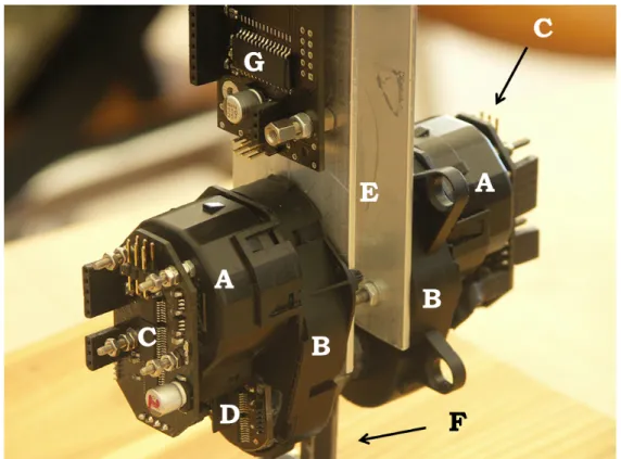
The implemented prototype is shown in Fig. 2.2. The two PM stepper mo- tors are denoted by (A) and the corresponding gearboxes by (B). On the top of the motors (C) denotes the magnetic encoders and the driving circuits. A3979 is
DOI:10.15774/PPKE.ITK.2013.003
Figure 2.2: Photo of the implemented prototype.
used as a motor driver along with a PIC24HJ12GP202 16bit microcontroller. The driver features internal PWM current control which reference value is updated by the microcontroller. (D) marks the optional load side encoder that measures the angular position of Link 2 respective to Link 1. The letters (E) and (F) indicate Link 1 and Link 2 respectively. The full motion control algorithm is implemented onboard that means a PIC24FJ16GA002 microcontroller responsible for the com- plete digital control (G). Personal computer is used only for data acquisition.
2.4 Modeling of the joint
2.4.1 Stepper motor model
The instantaneous torque of the permanent magnet stepper motor can be written as [38]
τ =−Km[iasin (Nrθ)−ibcos (Nrθ)], (2.1) where Km (Nm/A) is the motor constant, ia (A) is the current in phase a, ib (A) is the current in phase b, Nr is the number of the rotor poles, and θ (rad) is the
2. BIO-INSPIRED LOW-COST ROBOTIC JOINT WITH REDUCED LEVEL OF BACKLASH
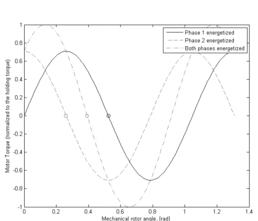
Figure 2.3: Normalized static torque characteristic of the stepper motor.
mechanical angle of the rotor.
Fig. 2.3 shows this static torque characteristic. It is modeled as a sinusoid-like function of the rotor’s angular position where the higher harmonics like the 4th harmonic (the cogging torque) are neglected. Both the one-phase and the two- phase excitations are plotted (the latter two-phase excitation was chosen since it offers more torque). The static torque is normalized and the stable points (o), that represent the rotor’s rest position if no external load applied, are marked.
Then the differential equation of the motor’s dynamic is given by d2θ
dt2 = −Kmiasin (Nrθ) +Kmibcos (Nrθ)−Bω
J (2.2)
where ω (rad/s) is the mechanical angular velocity, B (N m s/rad) is the viscous friction coefficient and J (Kg m2) is the inertia of the rotor.
The coils are excited with full-stepping method that can be written up in the
DOI:10.15774/PPKE.ITK.2013.003
Figure 2.4: Illustration of the backlash following way
ia = Isin (Nrθd) (2.3)
ib = Icos (Nrθd), (2.4)
where I (A) is the nominal current of the motors’ coil and θd is the desired angle where θd ∈π
4,3π4 ,5π4 ,7π4 .
2.4.2 Gear train and backlash model
First assume that the transmission of the motors is free of backlash and all the elastic deformations are neglected. In this case the angular position of the load can be written in the following forms
θl = θm1
n1n2 = θg1
n2 = θm2
n1n2 = θg2
n2, (2.5)
where n1 is the reduction ratio between the first and the second stage and n2 is between the second and the last stage. This linear formula turns to be highly non- linear once the effect of the backlash is added. Two different scenarios are usually distinguished. Contact Mode (CM) when the two mating gears are in contact and the Backlash Mode (BM) when these are disengaged [20]. Fig. 2.4 shows a gearplay between mating gears. The value of the backlash measured as a linear distance is
2. BIO-INSPIRED LOW-COST ROBOTIC JOINT WITH REDUCED LEVEL OF BACKLASH
Figure 2.5: Piecewise linear function for backlash modelling.
denoted by b. It can be approximated by using the angle β (rad) and the radius r1 as
b≈βr1, (2.6)
since β is a small angle. Similarly it is equal to the radius of Gear 2 multiplied by the angle of backlash measured on the second gear. In the literature there are different approaches to model the effect of the backlash [11, 12, 17, 22]. One of these is the contact model type that is using non-linear reaction forces [21]. The idea is to model the occurring contact between the mating gears with a non-linear elastic force that depends on the relative position (x) of the mating gears. The starting point (x= 0) is when the gears are at the center of the empty space. The relative position of the mating gears is defined as
x=r1θ1−r2θ2. (2.7)
For simplicity, a piecewise linear function is used to express the reaction forces, that can be seen in Fig. 2.5.
f(x) =
K(x+b/2) x <−b/2
0 |x| ≤b/2
K(x−b/2) x > b/2
(2.8)
The stiffness K and individual backlash b values are expected to be identical for all the stages of the gear trains. The numerical values are approximated by
DOI:10.15774/PPKE.ITK.2013.003
experimental results that are presented in Section 2.6. By using (2.7) the reaction force acting on the teeth of Gear 1 can be defined as
Fr =f(r1θ1−r2θ2), (2.9) and the torques of Gears 1 and 2, created by the reaction forces acting on the mating teeth are given by
τ1 = Frr1 (2.10)
τ2 = −Frr2. (2.11)
2.4.3 Complete model
The complete electromechanical model of the proposed joint is approximated as a five-inertia system that includes backlash and viscous friction. According to the naming conventions of Fig. 2.1, the index of m refers to the motor number and the first stage of the gearbox, g to the second stage, and l to the load and the last stage. Then by using (2.2), (2.6) and (2.9) the complete model becomes
d2θmj
dt2 = τmj−Bmωmj−Fmgjrm
Jm (2.12)
d2θgj
dt2 = −Bgωgj +Fmgjrgm−Fgljrgl
Jg (2.13)
d2θl
dt2 = τl−Blωl+ (Fgl1 +Fgl2)rl
Jl (2.14)
τmj = −Km
iajsin Nrθmj
−ibjcos Nrθmj
(2.15) iaj = Isin Nrθdj
(2.16) ibj = Icos Nrθdj
(2.17)
Fmgj = f(θmjrm−θgjrg) (2.18)
Fglj = f(θgjrg−θlrl), (2.19)
where j, that can be 1 or 2, denotes the element of the actuator pair. The B coefficients are the viscous damping coefficients and τl represents all the external forces acting on the load. Jm denotes the combined inertia of the motors and the first stage. Jg is the inertia of the intermediate stage andJl indicates the inertia of
2. BIO-INSPIRED LOW-COST ROBOTIC JOINT WITH REDUCED LEVEL OF BACKLASH
the load and the last stages. The numerical values were numerically computed on the available CAD drawings of the parts. The forces Fmgj are the reaction forces acting on the mating gears of the first stage (m) and the intermediate stage (g), and similarly Fglj is the reaction force of the intermediate and the last stage (l).
2.5 Motion control
The control input to the system is the angular velocity reference (ωref) of the joint.
As a first assumption this specifies the rate of change of the desired positions of the two motors. Therefore, the desired angular velocities of the motors are given by
ωd1 = ωref (2.20)
ωd2 = −ωref. (2.21)
An open-loop commutation scheme could enforce the desired angular velocity com- mand if proper acceleration and deceleration phases were added in order to prevent the loss of synchronism. That would imply the commonly used trapezoidal speed profile. Unfortunately even that could not guarantee the synchronism in the pres- ence of unknown external loads, therefore closed-loop commutation is used.
In order to keep the commutation synchronised with the rotor, error variables (2.22) are introduced
ej = θmj−θdj. (2.22)
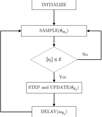
Fig. 2.6 shows the flowchart of the two individual motor commutation. In case of an open-loop commutation steps are issued with the necessary delay to achieve the required angular speed. By integrating the issued steps the desired angular position can be achieved (θdj). It can be easily seen that once the motor is not able to realize any of the required steps there will be an error (2.22) . In order to prevent the loss of synchronism, if the error is greater than a predetermined threshold (E=0.2 rad), the step must not be issued until the error falls below the threshold.
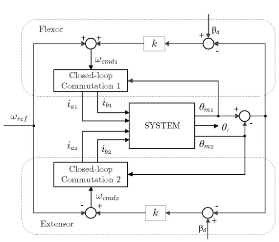
The closed-loop commutations of the stepper motors are just the low-level parts of the whole motion control. The high-level part is responsible for the generation of the commanded angular velocities (ω ). The block diagram of the complete
DOI:10.15774/PPKE.ITK.2013.003
motion control can be seen in Fig. 2.7. In order to reduce the level of backlash a cross-connected feedback is taken. βd is the desired level of angle difference and it is defined as
βd = btrm =βtn1n2, (2.23) where bt is the total backlash of the gearbox given as a linear distance, βt is the angle of the total backlash expressed at the last stage and k is a constant that sets the strength of the error feedback. As it can be seen in Fig. 2.7 the control tries to drive the actuators on the two sides (flexor and extensor) in a way to make βd−(θm1 −θm2) approach zero. The closer it drives to zero the less the resulting backlash will be. Then the position of the load can be approximated by
θl≈ θm1 +θm2
2n1n2 =θL. (2.24)
Since θl is also measured the comparison of the two trajectories become a good benchmark for the operation of the system.
Figure 2.6: Flowchart of the closed-loop commutation.
2. BIO-INSPIRED LOW-COST ROBOTIC JOINT WITH REDUCED LEVEL OF BACKLASH
Figure 2.7: Block diagram of the motion control of the joint.
2.6 Simulation and experimental results
For running the simulations MATLAB 8 was used with the help of the built-in numerical differential equation solver that is based on the variable step Runge- Kutta method.
In order to create a basis for comparison a new system is introduced. If one of the flexing-extending actuator pair is removed, a standard robotic joint would be achieved. Let the actuator denoted by index j = 2 be omitted, which means the motor and the gears are physically removed. The corresponding complete model will be the same as was derived previously but j is limited to one and Fgl2 is set to be zero. In the following, it will be referred to as the standard case and the original one as the flexor-extensor case.
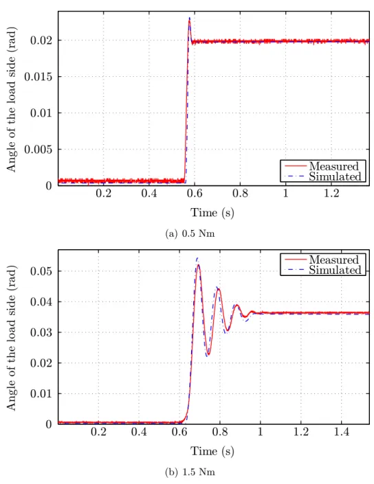
Fig. 2.8(a) and Fig. 2.8(b) illustrate two of the model validation results where the standard case was used. Both figures show the measured and simulated θlload positions as two different τ external load torques were applied at about t = 0.6s.
DOI:10.15774/PPKE.ITK.2013.003
Time (s)
Angleoftheloadside(rad)
0.2 0.4 0.6 0.8 1 1.2
0 0.005 0.01 0.015 0.02
Measured Simulated
(a) 0.5 Nm
Time (s)
Angleoftheloadside(rad)
0.2 0.4 0.6 0.8 1 1.2 1.4
0 0.01 0.02 0.03 0.04
0.05 Measured
Simulated
(b) 1.5 Nm
Figure 2.8: Results of the model validation.
The motors were excited with the maximum constant current in order to produce the maximum holding torque, that prevented the applied external torque to back- drive the motor. The position of the load was set to one extremum of the empty space created by the gearplay.
Then the applied external torque forced the load to move towards the other extremum. The smaller 0.5 Nm torque created a small overshoot that corresponds to the impact of the mating gears. The load position after the impact is just slightly bigger than the original backlash of the gearbox. The larger external torque caused
2. BIO-INSPIRED LOW-COST ROBOTIC JOINT WITH REDUCED LEVEL OF BACKLASH
Time (s)
MechanicalAngle(rad)
0.5 1 1.5 2 2.5 3 3.5
0 0.05 0.1 0.15 0.2 0.25 0.3
Load side Motor side
(a) Standard case - Simulation
Time (s)
MechanicalAngle(rad)
1 1.1 1.2 1.3 1.4
0.27 0.28 0.29 0.3 0.31 0.32 0.33
0.34 Load side
Motor side
(b) Zoom at the simulation
Figure 2.9: Simulation results of the standard case.
a bigger impact and showed a damped oscillatory motion with a settled position equal to almost the twice of the original backlash.
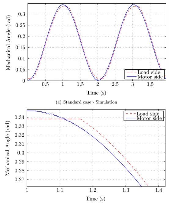
Figs. 2.9(a)-2.12(b) show the comparison of the new flexor-extensor approach with the standard approach. In both cases the same sinusoidal angular velocity reference (ωref) was given. Fig. 2.9(a) shows the simulation results of the mea- sured (θl) and approximated (θL) position of the load. Since there is no external disturbance the position of the load follows the position of the motors with a small
DOI:10.15774/PPKE.ITK.2013.003
Time (s)
MechanicalAngle(rad)
1 2 3
0 0.05 0.1 0.15 0.2 0.25 0.3 0.35
Load side Motor side
(a) Standard case - Experiment
Time (s)
MechanicalAngle(rad)
1.2 1.3 1.4
0.27 0.28 0.29 0.3 0.31 0.32 0.33
0.34 Load side
Motor side
(b) Zoom at the experiment
Figure 2.10: Experimental results of the standard case.
motion of the motors change direction the mating gears smoothly travel the empty space caused by the backlash. First it creates positional inaccuracy and further- more in the presence of external disturbances (e.g.: caused by other joints) it can create high impacts that has been shown in Fig. 2.8(b). The real measurement is showed in Fig 2.10(a) and the zoomed counterpart in Fig. 2.10(b). The curves show the raw signals that are not filtered and therefore contain some noise.
Now turning to the new approach, proposed in the dissertation, the simulation results obtained by using the flexor-extensor case depicted in Fig. 2.11(a). By using
2. BIO-INSPIRED LOW-COST ROBOTIC JOINT WITH REDUCED LEVEL OF BACKLASH
Time (s)
MechanicalAngle(rad)
0.5 1 1.5 2 2.5 3 3.5 4
0 0.05 0.1 0.15 0.2 0.25 0.3 0.35
Load side Motor side
(a) Flexor-Extensor case - Simulation
Time (s)
MechanicalAngle(rad)
1 1.1 1.2 1.3 1.4
0.28 0.3 0.32 0.34
Load side Motor side
(b) Zoom at the simulation
Figure 2.11: Simulation results of the Flexor-Extensor case.
the identical reference signal that was used before and recording the same system variables, the difference between the two curves dissappear. The enlargement in Fig. 2.11(b) also shows a significant reduction.
The experimental results of this approach showes similar effect in Fig. 2.12(a).
By zooming into the curves in Fig. 2.12(b) small deviations, that are comparable to the noise base of the sensor, become only noticable.
DOI:10.15774/PPKE.ITK.2013.003
Time (s)
MechanicalAngle(rad)
0.5 1 1.5 2 2.5 3 3.5 4
0 0.05 0.1 0.15 0.2 0.25 0.3 0.35
Load side Motor side
(a) Flexor-Extensor case - Experiment
Time (s)
MechanicalAngle(rad)
0.7 0.8 0.9 1 1.1
0.28 0.3 0.32 0.34
Load side Motor side
(b) Zoom at the experiment
Figure 2.12: Experimental results of the Flexor-Extensor case.
In order to have a quantitative comparison a specific mean value is defined as βc =
Z
T
max
θl(t)−θL(t) T
,βt
T
dt, (2.25)
whereT is the period of the sinusoid. This mean value gives a comparison basis to compare the results and gives an approximation of the remaining level of backlash.
Table 2.1 shows the qualitative results of the four test cases. We can conclude that the standard case almost exactly reproduced the level of original backlash. In the
2. BIO-INSPIRED LOW-COST ROBOTIC JOINT WITH REDUCED LEVEL OF BACKLASH
Table 2.1: Comparison of the results Configuration / Method βc
Standard / simulation 1.913×10⁻² rad Standard / experiment 1.892×10⁻² rad Flexor-Extensor / simulation 8.7×10⁻⁴ rad Flexor-Extensor / experiment 1.18×10⁻³ rad
standard case, the difference between the simulation and the experiment is about 1% (2.1×10⁻⁴ rad). This value for the proposed flexor-extensor case is slightly larger than 25% (−3.1×10⁻⁴ rad), which is caused presumably by the relatively low positional resolution, however the difference in absolute terms matches well with the preceding case. Comparing the standard and flexor-extensor case, simulation showes 1−0.00087 rad
0.01913 rad = 95.45% reduction in the avarage of the remaining backlash.
Real measurement showed 1 − 0.00118 rad
0.01892 rad = 93.76% reduction that is just slightly less compared to the simulation result.
All constants that are used during the simulations are listed in Appendix A Table 1.
2.7 Conclusion
A new improved actuation system for robotic joints has been described in this chapter. The proposed joint consists of two stepper motors that are operated in a flexor-extensor fashion inspired by the structure of human limbs. With this so- lution, a method was given for minimizing the effect of backlash by applying a simple high-level control algorithm. Real measurement data show a good match with simulation results and clearly supports the practical applicability of the ap- proach.
Based on the experimental results the mean reduction of the backlash was over 90%. More precisely, the theoretical 95.45% and the experimentally verified 93.76% results are comparable to the most effective Switching Strategy for backlash
DOI:10.15774/PPKE.ITK.2013.003
Figure 2.13: Implemented 11 DOF biped robot.
reduction that was reported [29] to reach 96.9%. However, it must be noted that the reported 96.9% is achieved with linear actuators for parallel manipulation.
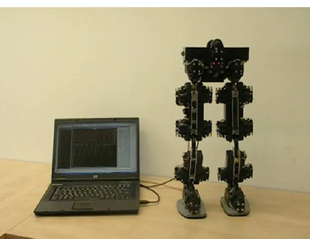
In addition, our previously built biped robot [3] has been successfully enhanced by using the proposed technique to reduce the backlash of the joints. In 2009, this 11 DOF biped robot was invited to a Japanese robotic exhibition held at Tatayama, where among the state-of-the-art humanoid robots, it was presented.
The robot is capable of walking in a statically stable manner. The photo of the biped robot standing next to its controlling computer can be seen in Fig. 2.13.
Chapter 3
A novel concept: The Emulated Elastic Actuator
DOI:10.15774/PPKE.ITK.2013.003
Nomenclature
N Pole number θ Angle [rad]
i Current [A]
V Voltage [V]
τ Torque [Nm]
R Resistance [Ω]
L Inductance [H]
ω Angular velocity [rad/s]
B Viscous friction [N m s/rad]
J Inertia [kg m2]
KT Motor constant [Nm/A]
I Nominal current [A]
k Spring constant [Nm/rad]
l Length [m]
η Viscosity [N m s/rad]
P Position (x,y) [m]
m Mass [kg]
F Force [N]
g Gravity (9.81 m/s2) U Potential energy [J]
K Kinetic energy [J]
t Time [s]
Superscripts
x0 Altered version of the variable x
˙
x Newton’s notation for time derivative ˙x= dxdt
Subscripts
raw Uncalibrated, pure encoder output
e Electronic
m Motor
a,b Phase a and b
ϕa, ϕb Binary code of phase a and b
d Desired
BEMF Back electromotive force ref Reference
h Hookean
r Resting
kv Kelvin-Voight
s Spring
l free end
a arm
cm Center of mass v Virtual spring
lv Linear Virtual spring ns Non-linear spring
GRF Ground reaction force
L Latency
DOI:10.15774/PPKE.ITK.2013.003
3.1 Introduction
The classical robotics requires the transmission between the actuator and the load to be very stiff. This is especially true for the industrial robots where positioning accuracy is essential. Since, by increasing the stiffness precision, stability, and bandwidth of the position-control can be improved. Therefore high mechanical stiffness is combined with high feedback gain in order to achieve the desired preci- sion in tasks like pick-and-place or robotic welding. In order to achieve positional accuracy most of the actuators use low torque electric motors with high gear ratios.
The gears introduce several undesired effects like friction and backlash that can be challenging to compensate for [19]. But in the last decade the tradition of ”the stiffer the better” seems to be changed.
Nowadays compliant actuator designs are gaining increasing popularity. One of the reason for that design is to overcome the limitations of a rigid transmission in terms of shock survivability, force control stability and human-safe operation. The poor shock surviving capability of the classical actuators comes from the rigidity of its structure. In addition to the lack of elasticity of the transmission the high gear ratio (N : 1) causes N2 increase in reflected inertia that is why higher forces on the gears are caused by shock loads. There has been an increasing interest in the field of human-centered robotics where close interaction between robot and human become unavoidable. It was usually dangerous if traditional actuators were used since, if high reflected inertia is combined with high friction of the gearing that could easily lead to damage to the environment when unknown contact occur [39].
To address these challenges several compliant actuator designs have been pub- lished. Maybe the most interesting and the one that had the greatest impact among these is the Series Elastic Actuator (SEA) [7] that belongs to the equilibrium- controlled stiffness type. It incorporates a physical spring at the output in series with a traditional actuator. One benefit of that elasticity is that the reflected iner- tia of the traditional actuator part becomes hidden by the spring. It low-pass filters the shock loads but it is not without a cost, it also low-pass filters the output of the actuator. It is a trade-off that has to be accepted. Another benefit of the SEA is that the problem of force-control is turned into a problem of position-control that makes easier to exert a given force. Finally the use of a spring allows the energy to be stored that can be useful for legged locomotion to increase its efficiency. Based on this concept numerous biped robots are built.
Another group of compliant actuators is the antagonistic-controlled stiffness.
3. A NOVEL CONCEPT: THE EMULATED ELASTIC ACTUATOR
A good example for this approach is the human arm where the flexor and extensor muscles are working against each other to be able to set the position and stiffness of the arm at the same time. A simple implementation of this type was reported by Shane et al. [40]. The difficulty is that in order to be able to vary the stiffness of the antagonistic joint two non-linear springs are needed. The size of the mechanism is therefore quite big that makes it less feasible. VSA [41] and especially VSA-II [42]
have a significantly smaller size but that comes for the price of a more complex structure. Another approach that falls into this category is the actuator with mechanically adjustable series compliance (AMASC) [43]. For setting the position and the compliance two separated motors are used and a biped called BiMASC was designed based on this concept.
Mechanically controlled stiffness is another type of compliant actuators where the stiffness is set by the point where an elastic element is fixed to the mechanism.
A good example is MACCEPA [44] that was built with standard off-the-shelf com- ponents. This is an advantage and a disadvantage in the same time, since it is easy to build but the whole structure space requirement is not so optimal. The approach called VS-Joint [45] from the German Aerospace Center (DLR) solved this issue by creating a more compact solution.
As it can be seen numerous solutions exist to create compliant actuation. All the aforementioned designs were passive approaches that means compliance comes from the natural dynamics of the mechanism. Common advantages of this kind of compliant actuators are the simple control, inherent safety and good efficiency.
The drawbacks are their more complicated mechanism, their bigger size, weight and usually these require two sperate motors that increase the cost. Though, there are simpler designs like the SEA that can be more optimal but these are having a pre-selected stiffness and it can only be changed by manually replacing the elastic element to a proper one.
Besides passive compliance, there is active compliance where compliant be- haviour is achieved by changing actively the natural dynamics of the mechanism.
A good example is the Lightweight Robot series (LWR I, II, III) [46] created by the DLR. It belongs to the soft-robotics and features joint level torque control.
The idea is to have a harmonic drive with high-gear ratio that already have some compliance. Then incorporating a torque sensor and a position sensor the compli- ant behaviour is reached with the help of a high-level control. Since the actuator is hardly backdrivable it is crucial to have a fast feedback loop otherwise perfor-
DOI:10.15774/PPKE.ITK.2013.003
even though during a sudden change in contact forces can easily exceed that limit.
Another way of creating active compliant actuation is by using SEA with active control. Radkhah et al. [47] presented a feedforward controlled emulated spring stiffness based approach. An SEA is used which have a fixed mechanical stiffness but setting the zero-torque position of the spring dynamically a ”virtual stiffness”
is achieved. The advantage of this design is its simplicity since it does not require any torque sensor or complex computation. The drawback is the lack of feedback that creates deviation from the expected result.
Bigge et al. [48] created a similar design with feedback. The elastic element is used as a torque sensor by measuring the angle of deflection. PID control is used to track the desired force profile that has been set according to the desired virtual spring characteristic. The benefit of the solution is that it can utilize the advantages of the original SEA like the improved shock survivability or the more stable force control. The drawback is the limited output response rate due to the incorporating SEA.
In the light of the foregoing, I propose a new concept of fully electric emulation of joint elasticity for biped robots and for other applications (patent pending).
I call it Emulated Elastic Actuator (EEA) after the SEA since, in fact it is an actuator that features emulated elastic behavior. The idea is to come up with a mechanism that has very low gear ratio, that is highly backdrivable, and has practically zero backlash and then use an electric motor, under a proper control, to produce the required torque in every time instance to mimic the behaviour of a physical spring. The first criterion, namely the low gear ratio, is necessary to handle the aformentioned problem of reflected inertia. The second one is closely related, since high gear ratio usually means high level of friction that when combined with high inertia yields to low backdrivability. The third one, the hard non-linearity of the transmission, has already highlighted in Chapter 2. It can be observed that, in almost all robotic applications these three criteria are not met at the same time.
Even, by using the industrial standard harmonic drive, to have the transmission free of backlash, the joints become hardly backdrivable due to significant level of friction. The reason why high gear ratios are used lies in the type of electric motors that are used by the engineering community.
Nowadays, in the field of robotics brushed Direct Current (DC) motors are getting replaced by Brushless DC (BLDC) motors. The successor less prone to wear out and features significantly less electromagnetic interference (EMI). Nevertheless, the operating speed of these motors has not been changed. These are usually
3. A NOVEL CONCEPT: THE EMULATED ELASTIC ACTUATOR
designed for thousands of RPM, which is far beyond the speed where the robotic joints are operated. Obviously, these motors need gears with high gear ratios, otherwise the actuators would be operated in a much lower efficiency region. A solution would be using motors with significantly lower speed but those are not commercially available.
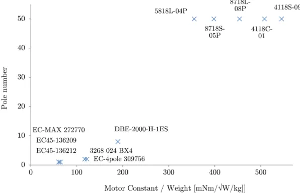
Off-the-shelf stepper motors are designed for lower speed, but are used in a substantially different operating scheme. As the name implies stepping is the desired motion of these motors. By properly energizing the coils of a stepper motor discreate steps are done, contrast to the DC motos where constant coil current creates continuous motion. Based on these, it is very unusal to use stepping motors in robotic joints, however those motors are mass produced and are designed for lower speed. To prove the advantages of the stepping motors over the ones that are currently used Fig. 3.1 shows a comparison of few different commercially available electric motors. The EC family is the product of the Maxon Motor Inc., 3268 024 BX4 is produced by FAULHABER Inc., DBE-2000-H-1ES belongs to Moog Inc., and the remainder are the hybrid stepper motors fabricated by the Linengineering Inc. It is a common approach to compare different motors by the motor constant. However, the selected motors are about the same weight but are
Figure 3.1: Comparison of different off-the-shelf electric motors.
DOI:10.15774/PPKE.ITK.2013.003
normalized to unit mass to improve the comparison. Surprisingly, all the motors with high motor constant belongs to the stepper type. The reason for that is the significantly greater number of poles that we can found in the stepper motors. This is in accordance with our previous statement since lower the pole number higher the speed.
We can conclude that, contrary to engineering practice, using stepper motor in a robotic joint can help us to meet the aformentioned criteria. But in the same time in order to use this type it requires a considerably different scheme of operation. In Section 3.3, the detailed model of the hybrid stepper motor (HSM) will be presented.
3. A NOVEL CONCEPT: THE EMULATED ELASTIC ACTUATOR
3.2 Concept of the Emulated Elastic Actuator
First of all, let’s consider a situation where gearing is neglected and therfore direct drive is assumed. As already pointed out in the previous section, HSM is a promis- ing alternative for the industry standard BLDC. Afterwards, equip the motor with a position sensor. It is preferred to be a magnetic encoder, but not limited to that type, optical or capacitive encoders could be used. The advantage of the magnetic type is that it is less prone to malfunction caused by dust (in Section 3.6, fur- ther comparison is carried out). In addition to the encoder, place a motor driver and a local controller that has moderate computational capability. Fig. 3.2 shows a possible arrangment of the system parts. The motor driver is preferred to be a transconductance type to achieve an accurate current control. In contrast to the industrial standard HSM commutation scheme, precise torque control must be used, that will be covered in Section 3.3. Now, we have a system that is capable of sensing its position and roughly speaking can be used to produce an arbitrary torque.
Based on these, in the following I am going to investigate the possibility of shaping the natural dynamics of the system by high-speed local control. More precisely, to design and implement an actuator that is capable of emulating different
Figure 3.2: A hybrid stepper motor with local controller.
DOI:10.15774/PPKE.ITK.2013.003
types of elastic behavior. In other words, to come up with a new concept of a universal actuator that can be used to change the way how it interacts with its environment.
The most important requirement is that the control must be local, in order to be able to realize high-speed operation (more than 20.000 iteration/sec). Until recently, the typical fastest torque control was in the range of 1-2 thousands of iteration per second, which is slower at least of one order than the proposed one.
A slower global control could be used to alter the parameters of the desired elastic behavior.
Importantly, high speed operation must be supported at commutation level.
Fig. 3.3 illustrates the block diagram of the proposed low-level system. The raw output of the encoder (θraw) is used for the calculation of the motor’s actual position (θm) and the ”electronic” angle (θe) that is necessary for the torque linearization.
In Section 3.3 the details of the motor characteristic’s linearization will be given.
The result of the linearization is two instantenous coil currents (iA and iB) there- fore a precise current control circuit is needed. For that purpose a Pulse-Width Modulation type motor driver is used that requires voltage as input to control
Figure 3.3: Block diagram of the electronic commutation.
3. A NOVEL CONCEPT: THE EMULATED ELASTIC ACTUATOR
the current. VϕA and VϕB are the two input voltages that are the outputs of the two Digital-to-Analog Converters (DAC A and DAC B ). The binary codes of the voltages are ϕA and ϕB.
The calculation of the position and the linearization of the motor’s charac- teristic is executed at the same 32-bit microcontroller (PIC32MX340F512H from Microchip Inc.) which iterates the emulation. The encoder is a TLE5012 from Infineon Inc., and the motor driver is a TMC246A (Trinamic Inc.). The complete electrical schematic is given in the Appendix.
The input of this subsystem is the desired motor torque (τd) and the output is the current angular position of the motor (θm). The idea is to create a fast feedback loop, that is iterated at 22 kHz, between θm andτd in order to be able to emulate different kind of elastic behaviors.
In order to further investigate the concept, the detailed model of the HSM will be presented.
DOI:10.15774/PPKE.ITK.2013.003
3.3 Model of the hybrid stepper motor
Hybrid stepper motors are combining the principles of variable-reluctance and the permanent magnet stepper motors, that was used in the previous chapter. The detailed investigation of the motor, however, is beyond the scope of the dissertation thus, only the details that are strongly related to the subject will be covered.
Therefore, the two phases (A and B) of a hybrid stepper motor having the following instantaneous torques
τA = −KTiAsin(θe) (3.1)
τB = KTiBcos(θe), (3.2)
where higher harmonics are neglected, KT is the motor constant,iA andiB are the coil current in phase A and B, respectively and
θe =θmN (3.3)
is the ”electronic” or commutation angle, where θm is the position of the motor’s shaft and N is the number of poles.
In fact, due to fabrication inaccuracies the real torques (Fig. 3.4) differ from our approximation, but it is a common approach to assume (3.1)-(3.2).
The total torque produced by the motor can be written as the sum of the two
Mechanical motor angle, [rad]
Normalizedmotortorque[%]
0 0.05 0.1 0.15
−1
−0.5 0 0.5
1 C oil A real
C oil A ap p r.
C oil B real C oil B ap p r.
Figure 3.4: This figure shows the instantaneous torque produced by the two phases being energized at the rated current.