Author’s Accepted Manuscript
Influence of structure on the hardness and the toughening mechanism of the sintered 8YSZ/MWCNTs composites
Soukaina Lamnini, Zoltán Károly, Eszter Bódis, Katalin Balázsi, Csaba Balázsi
PII: S0272-8842(18)33324-8
DOI: https://doi.org/10.1016/j.ceramint.2018.11.207 Reference: CERI20181
To appear in: Ceramics International Received date: 28 October 2018 Accepted date: 26 November 2018
Cite this article as: Soukaina Lamnini, Zoltán Károly, Eszter Bódis, Katalin Balázsi and Csaba Balázsi, Influence of structure on the hardness and the toughening mechanism of the sintered 8YSZ/MWCNTs composites, Ceramics International, https://doi.org/10.1016/j.ceramint.2018.11.207
This is a PDF file of an unedited manuscript that has been accepted for publication. As a service to our customers we are providing this early version of the manuscript. The manuscript will undergo copyediting, typesetting, and review of the resulting galley proof before it is published in its final citable form.
Please note that during the production process errors may be discovered which could affect the content, and all legal disclaimers that apply to the journal pertain.
www.elsevier.com/locate/ceri
Influence of structure on the hardness and the toughening mechanism of the sintered 8YSZ/MWCNTs composites
Soukaina Lamnini
1, 2, Zoltán Károly
3, Eszter Bódis
3, Katalin Balázsi
2, Csaba Balázsi
2*1Doctoral school of Material Science and Technologies, Óbuda University, Bécsi str.96/B, 1034 Budapest, Hungary
2Institute for Technical Physics and Materials Science, Centre for Energy Research, Hungarian Academy of Sciences, Konkoly – Thege M. str. 29-33, 1121Budapest, Hungary
3Institute of Materials and Environmental Chemistry, Research Centre for Natural Sciences, Hungarian Academy of Sciences, Budapest, Hungary
*Corresponding author: balazsi.katalin@energia.mta.hu, Tel. +36 1 392 2249
Abstract
Composites consisting of 8 mol.% yttria-stabilized zirconia (8YSZ) and 1 wt.%, 5 wt.% and 10 wt.%
multiwall carbon nanotubes (MWCNTs) have been prepared by attrition milling and spark plasma sintering (SPS). The effect of sintering temperature and MWCNT content on the microstructural features including apparent density, phase transition, crystal size and mechanical properties were investigated. The phase transformation during the sintering process was observed with X-ray diffraction. The MWCNT stability was investigated by Raman spectroscopy. Vickers hardness and indentation fracture toughness of 8YSZ/MWCNTs composites were evaluated and compared with reference 8YSZ composite. The crack propagation mechanisms of composites were determined.
MWCNT pull-out, crack bridging and crack deflections were found and constituted a key factor of fracture toughness enhancement in the composites with MWCNT addition.
Keywords: 8YSZ /MWCNT; hardness; crack propagation mechanisms; SPS
1. Introduction
The important structural properties of zirconium dioxide named also zirconia made this material widely investigated for many applications where high strength, high toughness, high ionic conductivity and good stability at high temperature are required [1]. Thanks to its high ionic conductivity, zirconia composites play an important role in solid oxide fuel cells (SOFC) devices operating at high temperature [2]. Indeed, in these high efficient and environmental friendly power generation devices, zirconia enables the transfer of oxygen ion from the air cathode to the anode which is mostly based on Ni-YSZ [3]. Zirconia is known to have three phases: monoclinic phase below 1170 °C, tetragonal phase between 1170 °C and 2370 °C, or cubic phase stable at very high temperature above 2370 °C. The transition from monoclinic→ tetragonal→ cubic induces a volumetric change of zirconia lattice. Usually, to stabilize zirconia cubic and tetragonal phase at room temperature many typical dopants can be introduced for instance: Y2O3, Mg3N2, MgO and CaO [4]. Also, to stabilize cubic phase high amount of dopant (8YSZ) is required. However, 3YSZ (3 mol% Y2O3) is enough to stabilize tetragonal phase. Some studies claimed that the presence of small carbon fraction into cubic zirconia composite may boost its stability at room temperature [5]. Despite of the wide- ranging application of ceramics, they are still limited by their dramatic brittleness to be effective in several applications. The incorporation of conductive nanosized materials into ceramic matrix such as: multiwall carbon nanotubes (MWCNTs), single walled carbon nanotubes (SWCNTs) graphene or boron nitride nanotubes (BNNTs) led to a significant enhancement in the mechanical as well as electrical properties [6]. Thanks to their superior properties, nano-conductive material forms an additional resistance barrier when the stress is applied resulting in pull-out, crack bridging and crack deflection [7]. However, several authors reported dissimilarities of the nanostructured materials effectiveness into ceramic matrix. Indeed, this can be due to several obstacles that might be overcome during the preparation period, or sintering treatment. The typical obstacles include (i) difficulty to uniform MWCNTs dispersion into zirconia matrix, causing a tremendous defects and agglomerations issues, (ii) conductive nanosized materials mainly CNT and graphene can be easily damaged by the high sintering temperature and therefore, react with the oxide matrix [8]. Spark plasma sintering (SPS) an advanced and rapid technique for ceramic consolidation showed minimal damage and high densification for ceramic based nanoconductive materials [9]. L. Melka et.al studied tetragonal zirconia polycrystals doped with 3 mol.% yttria (3Y-
TZP) and multiwalled carbon nanotubes (MWCNTs) content from 0.5 to 4 wt.% [10]. A strong increase in the electrical conductivity for the sintered composite with 0.5 wt.%
MWCNTs content has been claimed. J.-J. Xu et. al. used boron nitride nanotubes (BNNTs) instead of CNT or graphene to improve zirconia fracture toughness [11]. BNNTs with 0.5 wt.%, 1 wt.% and 2 wt.% were added to zirconia matrix. The highest flexural strength and fracture composite were found in the composite with 1 wt.% of BNNTs (1143.3 MPa and 13.13 MPam1/2,respectively). A. Duszova et.al. studied the effect of CNTs content on the mechanical and electrical properties of monolithic zirconia [12]. The addition of the CNTs decreased the hardness and indentation toughness from 1297 kg/mm2 to 830 kg/mm2 and from 8.01 MPam0.5 to 5.6 MPam0.5, respectively. This fact was attributed mainly to the residual porosity remained in the material after sintering. A. Gallardo-López et. al. prepared yttria tetragonal zirconia ceramic composites with 1 vol.%, 2.5 vol.%, 5 vol.% and 10 vol.%
nominal contents of graphene nanoplatelets (GNPs) [13]. The mixture was synthesized using ultrasonic probe agitation of graphene nanoplatelets. Fully dense composites were obtained after sintering at 1250 °C for 5 min. The Vickers hardness decreased with GNP content from 13.9 GPa in 3YTZ to 8.1 GPa in 3YTZ with 10 vol.% GNPs. Moreover, significant hardness anisotropy was obtained in the perpendicular plane to the sintering compared to the cross section. This anisotropy augmented with GNP content. A.M. Zahedi et.al. compared the effectiveness of CNTs dispersion in wet and dry media to avoid agglomerations [14]. The density of the samples prepared in wet media was generally higher compared to dry media samples. This was attributed to high CNTs homogeneity found in wet media method.
In this work, the effect of sintering temperature and MWCNTs content on mechanical behavior of 8YSZ/MWCNTs compositeshas been studied.
2. Experimental procedure
2.1. Starting materials and sintering processes
The preparation of three zirconia composites (ZrO2 /8 mol. % Y2O3, Sulzer Metco AMDRY 6643) with 1 wt.%, 5 wt.% and 10 wt.% multiwall carbon nanotubes addition (MWCNTs, type NC3100™, Nanocyl) has been carried out. The structural properties of MWCNTs were investigated using High Resolution Transmission Electron Microscopy (HRTEM). The powder mixtures including the reference without any addition of MWCNTs were milled with
130 g ethanol and 280 mL zirconia balls (each of 1 mm in diameter) to reach high dispersion of MWCNTs in the 8YSZ matrix from one side, and to increase the surface area of the grains by decreasing their size from another side. High efficient attrition milling (Union Process, type 01-HD/HDDM) was performed at 4000 rpm for 5 h. The powders were then dried at 172
°C for 25 minutes, and filtered with mesh size of 100 μm. The powders mixtures were sintered at 1400 °C by Spark plasma sintering (SPS, HD P5 equipment FCT GmbH) using a graphite die. The details of preparation are presented in Tab. 1. An optical pyrometer positioned on the upper graphite punch has been applied for temperature control. The powder mixtures were then heated under vacuum (1mbar) at a rate of 200 °C/ min−1 with on/off current pulses of 3/1 ms, 2.2 kA and 5 V. An uniaxial pressure of 50 MPa was maintained during sintering cycle with a dwell time of 5 min. The final sintered pellet size was 30 mm in diameter with a thickness of 5 mm. The pellets were grounded and polished using silicon carbide papers from 80 µm to 1200 µm. Additional polishing has been applied for some samples to ensure the total removal of the graphite foil using polycrystalline diamond suspension. The specimens were sawed into bars of about (4.8 mm × 4.4 mm × 30 mm) by diamond cutting (Struers secotom-50).
Table1
2.2. Density and mechanical measurements
The apparent and bulk densities of the composites were measured using Archimedes method (Equation 1 and 2 respectively) with water as the immersion medium. Some composites with high surface porosity have been immersed into water + lubricant (soap) for at least 3 days to ensure the total filling of the pores. Further, the apparent porosities of the composites were calculated according to (Equation 3).
(1)
(2)
(3)
where, is water density equal to 1g/cm3 at room temperature, (wt) refers to the weight in (g).
The diagonal length (d) was measured with Vickers hardness test (Leitz Wetzi AR Germany) at a load of 19.61 N with a dwell of time of 30 s for each polished composites. 7 indents have been performed throughout the sample’s surface diagonal with a displacement step of 4 mm, to investigate the hardness homogeneity. The hardness values were estimated according to (Equation 4):
(4)
where, F is the applied load (N), d is the diagonal length (mm) and Hv is the estimated hardness (GPa). Fracture toughness (KIC) was obtained using the valid equation (5) proposed by Shetty [15]:
( )
(5)
where, l (mm) is the length of the crack from the indentation corner.
X-ray diffraction (XRD) analysis was carried out to evaluate new phase occurrence during the sintering process that might be caused by the high amount of MWCNT in contact with 8YSZ matrix. Phase identification and a standard less quantitative analysis of the composites were performed using the Bruker Diffrac. EVA software based on the ICDD JCPDS 2003 data base. Standard less quantitative analysis method is based on the comparison of the peak intensities of the identified phases to the intensities of a corundum standard [16]. High and low magnification micrographs were recorded by Scanning Electron Microscopy (SEM, LEO1540 XB) to understand the different physical phenomenon in accordance with the experimental results namely surface porosity, MWCNT pull-out, crack bridging, crack deflection. Raman spectroscopy is a non-destructive method to investigate the atomic bonding properties and the microstructure. Renishaw 1000 B micro-Raman spectrometer attached to a
Leica DM/LM microscope was used to examine Raman spectroscopy at room temperature in the wavenumber range of 150 - 3500 cm-1 with 488 nm laser excitation. The spectral resolution of the system is 2.5 cm-1 and the diameter of the excitation spot is 1 µm.
3. Results and discussion
3.1. Density and microstructure
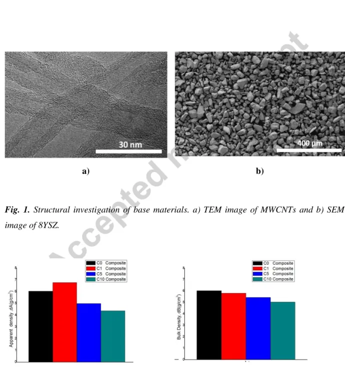
Reference yttria-stabilized ZrO2 (8YSZ) exhibited an average grain size of about 40 μm and cubic phase as a main structural feature (Fig. 1). MWCNTs inner/outer diameter was 3.8 nm and ) 9.13 nm, respectively.
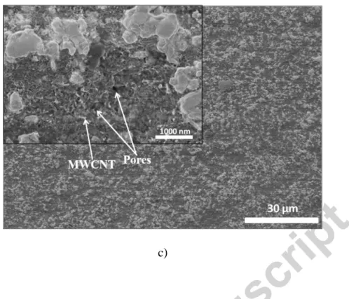
The diameter of the MWCNTs varied from 7 to 9 nm. The apparent and bulk density measurements of the sintered composites are illustrated in (Fig. 2a) and (Fig. 2b), respectively. The highest apparent density was achieved with 1 wt.% of MWCNTs addition (6.76 g/cm3, C1 composite) followed by 6.02 g/cm3 found in C0 composite. However, the apparent density dropped to lower values with increasing MWCNTs content. Inversely the bulk density showed a slight rise in the case of C5 and C10 composites compared to their apparent density from 4.97 g/cm3 to 5.44 g/cm3 and from 4.36 g/cm3 to 5.02 g/cm3, respectively. However, the bulk density of C1 decreased to 5.80 g/cm3 and standalone 8YSZ (C0 composite) maintained practically the same relative density. The increase in bulk density at high amount of MWCNTs could be attributed to the additional pores volume between and inside the particles taken into consideration during its evaluation. A detailed graph considering the apparent porosity of the composites is illustrated in (Fig. 2c). The apparent porosity revealed close results between (C0 / C1) composites on one hand and between (C5/C10) composites on the other hand. Therefore, the four composites can be divided into two categories.
The first category is the so-called close pore composites referring to C0 and C1 composites and having minimal/maximal porosity of (~ 33 %, ~16.5 %) respectively. While, the second category is considered as composites with open pores (C5 and C10) with minimal/maximal porosity of (~ 41.6 %, ~ 50 %) respectively. SEM images performed on the polished cross sections surface for both category of samples with closed and open pore are depicted in Fig.3.
The detailed surface morphology in the inset image revealed at first sight a smooth, homogeneous and tenacious surface for standalone 8YSZ (Fig. 3a).
Additionally, the surface area of C1 composite (Fig. 3b) was mainly predominated by nano- metric dark spot reflecting a good MWCNTs distribution in 8YSZ matrix and a high interfacial bonding resulting in a microstructure refinement. However, a small fraction of dark spot with a bigger size ranged approximately from 2 μm to 4 μm has been also observed and refers to MWCNTs aggregation. By contrast, it is most remarkable that the surface morphology of the YSZ containing high amount of MWCNTs 10wt% (Fig. 3c) exhibits a reduced interfacial bonding between 8YSZ and MWCNTs, a deep superficial porosity and high agglomeration of MWCNTs. These effects, led to form a rough surface and discontinuous 8YSZ particles embedded in a dark phase composed by MWCNTs agglomerations.
3.2. Phase composition of 8YSZ/MWCNTs composites
XRD analysis was performed on the sintered samples to determine the phase composition.
XRD patterns (Fig. 4) revealed the presence of cubic and tetragonal zirconia phases in all the composites including reference and the monoclinic phase only in the composites with MWCNTs. The strongest peak was conducted by both cubic (PDF89_9069) and tetragonal (PDF80_2155) phase appearing at 2ϴ of 30.119 ° and 30.270 °, respectively. The following two intense peaks refer to the tetragonal phase at 2ϴ of 50.424 ° and 59.816 °. Other peaks of cubic phase with minor intensity were seen at 2ϴ of 34.918 °, 62.617 ° and 81.669 °. The YSZ monoclinic (PDF65_1023) phase was perceived mainly at a high amount of MWCNTs (C5 and C10) at 2ϴ of 28.06 ° and 31.3 °.
Tab. 2. summarizes and quantifies the structural phase transition with the corresponding crystal size perceived in each composite according to MWCNTs content sintered at 1400 °C.
At powder state, the cubic phase was recorded as a main phase composing C0, C1, C5 and C10. The current XRD investigations revealed the appearance of new phases namely tetragonal and monoclinic resulting from sintering process by SPS at 1400 °C. In the case of 8YSZ ceramic C0, a huge percentage of phase transition from cubic to tetragonal was found, about 24.8 % cubic via 75.2 % tetragonal. The cubic phase was higher, while the tetragonal phase decreased in C1, C5 and C10 compared to YSZ ceramic. The minor monoclinic phase in C1, C5 and C10 resulted mainly from tetragonal phase transition.
3.3 Stability of MWCNTs in composites
Scanning Raman spectroscopy measurements were performed to confirm the presence of MWCNT in the composites and determine structural changes caused by sintering. Four typical Raman spectra are shown in the 150 - 3500 cm-1 wavenumber region, which were measured on composites with different MWCNT content (Fig. 5). In case of pure YSZ (reference, C0, black line) scattering peaks related to yttria stabilized zirconia which are in accordance with literature works [17,18]. Characteristic Raman peaks of YSZ are less intensive or completely absent in case of YSZ / MWCNTs composites (C1, C5 and C10) in the 100 to 700 cm−1 wavenumber region. Additional strong peaks have been observed around 1590 cm-1 (G band) and 1355 cm-1 (D band), which are related to the MWCNT [19]. The G band is related to the stretching vibration of the sp2 C-C bonds, while the D band is associated with the presence of structural defects in the MWCNT. Raman spectra also exhibited a wide band at higher wavenumbers, the so called 2D band, which appears at 2687 cm−1, 2684 cm−1 and 2690 cm−1 for 1 wt.%, 5 wt.%, 10 wt.% MCWNT content, respectively. The 2D band feature originate in a two-phonon, second-order Raman scattering process in carbon nanotubes [20].
The intensity ratio of D and G band (ID/IG) has been widely used to investigate the structural purity (structural defects and disordering) of MWCNTs or the presence of agglomerations [21-22], hence the intensity of D band is defect dependent. In principle, the larger the number of defects, the higher the D band intensity. Peak positions and intensity of distinct scattering bands were determined by Lorentzian fitting of Raman spectra shown in Fig.5. Although such procedure has some uncertainty because of the number of free parameters, it can provide additional information about the YSZ / MWCNTs composites. We found that the ID/IG ratio is 0.6 for C1, 0.9 for C5 and 0.8 for C10, which values are in good accordance with previous morphological observations showing the presence of structural defects and agglomerations in the YSZ / MWCNTs composites as a result of sintering. Among the composites, C5 contains MWCNTs with more structural defects compared to the others according to its highest ID/IG ratio (0.9).
3.4. Mechanical properties of 8YSZ/MWCNTs composites
Ceramic based conductive nanosized material resist differently to a compressive and uniform stress as reported by the literature. A number of studies are currently available on zirconia
reinforced with MWCNTs, single-walled carbon nanotubes (SWCNTs), double-walled carbon nanotubes (DWCNTs) or graphene. M. Michálek.et .al studied the mechanical properties of incorporating 1 vol.% of MWCNTs into alumina, and alumina/zirconia matrices. They found an increase of about 8 % and 35 % in fracture toughness for both composites respectively, compared to the monolithic alumina (reference) [22]. J-H. Shin. et. al fabricated yttria- stabilized zirconia (YSZ) ceramics reinforced with reduced graphene oxide (RGO) by spark plasma sintering (SPS). The composite hardness was decreasing with RGO addition, while the fracture toughness undergoes an increase from 4.4 to 5.9 MPa1/2 [23]. A. Kasperski et .al studied the mechanical properties of YSZ/DWCNTs composites sintered by (SPS) with carbon contents up to 6.3 wt.%. In that study the highest mechanical properties (σf 694 MPa, KIc 7 MPam1/2) were obtained for the composite with low carbon contents 1.2 wt.%. (σf) and (KIc) refers to the fracture strength and the single-edged notched beam fracture toughness respectively. However, the fracture toughness was inferior to that of standalone YSZ ceramic [24]. The behaviour of zirconia matrix under a certain applied compressive load changed with the addition of MWCNTs. In fact, the matrix dissipates the applied stress to MWCNT fibres.
This mechanism played an important role in improving the fracture toughness of the composites. MWCNT pulling-out, crack bridging, crack deflection and branching are among the typical phenomena resulting from toughening zirconia with MWCNTs.
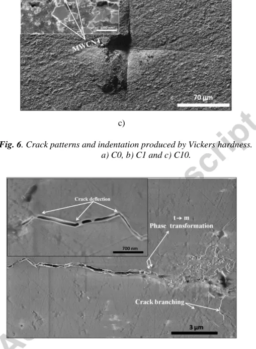
The properties of MWCNTs are considered as crucial factors that control the efficiency of stress transferred from the matrix to the fibre. The indentation and the crack propagation in the different categories of the samples namely first group with closed pores (YSZ, YSZ/1 wt.% MWCNTs) and second group with open pores (YSZ/10 wt.% MWCNTs) sintered at 1400 °C, have been carefully examined and magnified under SEM. As delineated in Fig. 6.
MWCNTs pulling-out and bridged region are visible in the reinforced YSZ with 1 wt.%
composite (Fig. 6b). Two interesting observations were noticed during the crack propagation analysis between the standalone matrix and the reinforced matrix with 1 wt.% MWCNTs.
Generally, the average crack path length calculated from the indentation centre was more or less higher than that of the unreinforced matrix about 50 µm via 46 µm. This could be attributed to the residual porosity induced by the MWCNTs (Fig. 6b). Further, the crack widths were narrowed to an average 76 µm compared to that of the standalone matrix 120 µm. Indeed, the observed bridged regions in the reinforced composite form an obstacle that protect the crack from reaching a critical state and consequently prone to failure. Thus, the
crack path appears more restrained and tapered. On the other hand, the pull-out of MWCNTs occurs when the transferred stress exceeds the interfacial shear stress, the latter depend largely on the number of MWCNT walls, their thickness, elastic modulus, and volume fraction [7].
Conversely, an inconsistent matrix was observed in the case of 8YSZ containing 10 wt.% of MWCNT (Fig. 6c). The incoherence in 8YSZ matrix containing 10 wt.% MWCNTs composite was attributed to discontinuity of zirconia particles and deep open porosities on surface. Moreover, (Fig. 6c) draw clearly the aggregation of MWCNTs that degrades the fracture toughness resistance, similar results have been reported by numerous studies [25]. In this case, the dispersion of the stress occurs throughout the pores starting from the centre of indentation and ending after a long unrestrained path. Thereby, this material exhibited low mechanical properties. Fig. 7 indicates the contribution of crack deflection and crack branching in the toughening mechanism for C1 composite. It was assumed that crack deflection takes place when the crack tends to follow the grain boundaries and therefore reflects the composite microstructure [26].
Furthermore, the possibility of phase transformation occurrence from metastable tetragonal zirconia to monoclinic was highly believed in 8YSZ/1 wt.% MWCNTs composite. The existence of microcrack along the crack path axes as marked in Fig.8 provides the evidence of lattice volumetric expansion. Additionally, the difference of thermal expansion coefficient (CTE) mismatches between zirconia matrix (10.3×10⁻⁶ °C-1) and MWCNT (1.6-2.6×10⁻⁵°C-1), must be taken into account during the estimation of the overall structural phenomenon involved in improving the toughness of ceramic composites. Thermal expansion coefficient depends on several properties of the composite constituent. For instance, micro structural phases, the distribution and the volume fraction of MWCNTs into ceramic matrix, and finally the interaction features between the grains and the fibres especially at large volume fractions [27]. Therefore, thermal residual stress is often provoked during the cooling state of the composites at room temperature as a result of (CTE) differences. The residual stress in composites can be expressed as [28].
(6)
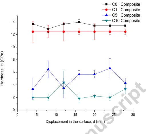
Fig. 8 illustrates the Vickers hardness results of 8YSZ/MWCNTs composites sintered at 1400
°C in function of surface displacement. The variation of Vickers hardness with surface displacement was practically homogenous and reached high values 13.49 GPa for 8YSZ ceramic and 12.44 GPa for 8YSZ containing 1 wt.% of MWCNTs. The average hardness for C5 and C10 composites decreased sharply to low values 5 GPa and 2.7 GPa successively.
Fluctuations reflecting the non-homogeneity of Vickers hardness were highly indicated in C5 and C10 curves. The experimental hardness measurements confirmed the previous microstructural investigation shown in Fig. 3, 6 and 7.
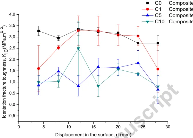
The indentation fracture toughness at different positions of 8YSZ/MWCNTs composites were comparable with 8YSZ composites (Fig. 9). The fracture toughness variation line of C1 had initially an upward trend followed by a flat band region where the two variations lines of C1 and C0 were almost overlapping each other at an average ~ 3.2 MPa.m0.5. In some positions we noticed that C1 line slightly exceed that of C0 (3.2 MPa.m0.5 via 2.6 MPa.m0.5) before it dropped back again to its initial value. On the other hand, the fracture toughness decreased rapidly to low values 1.5 MPa.m0.5 and 1.3 MPa.m0.5 when MWCNTs content has been increased to 5 wt.% and 10 wt.% respectively. The improvement of the fracture toughness in some positions of C1 composites is originated from the previously discussed toughening mechanisms (MWCNT pulling-out, crack bridging, crack deflection, crack branching and phase transformation) confirmed by SEM investigation assessed upon the composite surface before and after the indentation.
Conclusion
The present investigation of YSZ/MWCNTs composites prepared by attrition milling and SPS at 1400°C conducted mainly to the following conclusions:
- The structural investigation of 8YSZ and 8YSZ/1 wt.% MWCNTs revealed smooth and homogeneous surfaces. Inversely, when MWCNTs content increased the surface unveiled a reduced interfacial bonding between 8YSZ and MWCNTs, and deep open porosity on surface. This in turn led to low mechanical properties.
- Increase of MWCNTs content influenced phase transition from cubic to tetragonal and the increase in the monoclinic phase after sintering.
- The Raman investigations proved the stability and integrity of MWCNTs in composites - The variation of Vickers hardness with surface displacement was practically homogenous and reached high values 13.49 GPa for YSZ and 12.44 GPa for YSZ/1 wt.% MWCNTs.
The indentation fracture toughness of YSZ/1 wt.% composite was mostly equal or higher than that of YSZ (÷ 3.2 MPa.m0.5).
Acknowledgement
The authors acknowledge the support given by the Hungarian National Research Development and Innovation Office for the funding of FLAG-ERA “Multifunctional Ceramic/Graphene Coatings for New Emerging Applications”, COST Action CA15102 Solutions for Critical Raw Materials under Extreme Conditions and project No. VEKOP- 2.3.2-16-2017-00013 supported by the European Union and the State of Hungary, co-financed by the European Regional Development Fund. Authors thank Dr. Z.E. Horváth and Dr. Zs.
Fogarassy from MTA EK for their help with XRD and TEM, and Mr. Levente Illés from MTA EK for SEM measurements.
References
[1] Jianan Su, Yao Chen, Qiqi Huang. Graphene nanosheet-induced toughening of yttria- stabilized zirconia. Appl. Phys. A. 2017: 123–10.
[2] Shirjeel M, Seung-Bok L, R-H Songa, et al. Fundamental mechanisms involved in the degradation of nickel–yttria stabilized zirconia (Ni–YSZ) anode during solid oxide fuel cells operation: A review, Ceram. Int. 2016; (42): 35–48.
[3] Hideto K, Yoshiyuki S, Toshihiko Y, et al. Properties of Ni/YSZ cermet as anode for SOFC. Solid State Ionics. 2000; 132: 253–260.
[4] Yue-Feng Z, Lei Shi, Liang Ji, et al. Synthesis of zirconia nanoparticles on carbon nanotubes and their potential for enhancing the fracture toughness of alumina ceramics Composites: Part B. 2008; 39 (7): 1136–1141.
[5] Shimada S. Microstructural observation of ZrO2 scales formed by oxidation of ZrC single crystals with formation of carbon. Solid State Ionics. 1997; 101: 749–53.
[6] Sable PA, LaJeunesse J, Sullivan C, et al.V. Dynamic compaction of yttria-stabilized zirconia with the addition of carbon-nanotubes. A.I.P. 2017; 1793: 120004-1–120004-6.
[7] Neelima M, Ambreen N, Pratyasha M, et al. Effect of far-field stresses and residual stresses incorporation in predicting fracture toughness of carbon nanotube reinforced yttria stabilized zirconia. J. Appl. Phys. 2017; 122: 104–145.
[8] Zhou J.P, Gong Q.M., Yuan K.Y., et al. The effects of multiwalled carbon nanotubes on the hot-pressed 3mol% yttria stabilized zirconia ceramics. Mater. Sci. Eng. A. 2009; (520):
153–157.
[9] Garmendia N, Grandjean S, Chevalier J, et al. Zirconia-multiwall carbon nanotubes dense nano-composites with an unusual balance between crack and ageing resistance. J. Eur.
Ceram. Soc. 2011; (31): 1009–1014.
[10] Melka L, Anttic M L, Anglad M. Material removal mechanisms by EDM of zirconia reinforced MWCNT nanocomposites. Ceram. Int. 2016; (42): 5792–5801.
[11] Xua J J, Baia Y J, Wanga W L, et al. Toughening and reinforcing zirconia ceramics by introducing boron nitride nanotubes. J. Mater. Sci. Eng. A. 2012: (546): 301–306.
[12] Annamaria D, Dusza J, Tomsek K, et al. Zirconia/carbon nanofiber composite. Scripta Mater. 2008; (58): 520–523.
[13] Gallardo-López, A., Ceramics International (2017),
http://dx.doi.org/10.1016/j.ceramint.2017.06.007.
[14] A.M. Zahedi, J. Javadpour, H.R. Rezaie and M. Mazaheri,Analytical Study on the Incorporation of Zirconia-based Ceramics with Carbon Nanotubes: Dispersion Methods and Mechanical Properties, Ceramics International, http://dx.doi.org/10.1016/j.ceramint.
2015.09.118.
[15] Shetty DK, Wright IG, Mincer PN, et al. Indentation fracture of WC-Co cermets. J Mat Sci. 1985; 20: 1873–8220.
[16] Smith DK, Johnson GG. Scheible A, et al. Quantitative X-Ray Powder Diffraction Method Using the Full Diffraction Pattern. Powder Diffr. 1987; 2(2): 73-77.
[17] Ghosh, A.; Suri, A.K.; Pandey, M.; Thomas, S.; Rama Mohan, T.R.; Rao, B.T.
Nanocrystalline zirconia-yttria system–a Raman study. Mater. Letters 2006, 60, 1170–1173.
[18] Cai, J.; Raptis, Y.S.; Anastassakis, E. Stabilized cubic zirconia: A Raman study under uniaxial stress. Appl. Physics Letters 1993, 62, 2781.
[19] Bokobza, L.; Zhan, J. Raman spectroscopic characterization of multiwall carbon nanotubes and of composites. eXPRESS Poly. Letters 2012, 6, 601–608.
[20] Dresselhaus, M.S.et al. Raman spectroscopy of carbon nanotubes. Physics Reports 2005, 409, 47–99.
[21] Antunesa, E.F. Lobo, A.O., Corata, E.J.; Trava-Airoldia, V.J.; Martin, A.A. Verisimo, C. Comparative study of first- and second-order Raman spectra of MWCNT at visible and infrared laser excitation. Carbon 2006, 44, 2202–2211.
[22] Michálek M, Sedláčeka J, Parchoviansky M, et al. Mechanical properties and electrical conductivity of alumina/MWCNT and alumina/zirconia/MWCNT composites. Ceram. Int.
2014; 40(1): 1289-1295.
[23] Shin JH, Seong HH. Fabrication and properties of reduced graphene oxide reinforcedyttria-stabilized zirconia composite ceramics. J Eur Ceram Soc. 2014; 34: 1297–
1302.
[24] Kasperski A, Weibeln A, Alkattan D, et al. Double-walled carbon nanotube/zirconia composites: Preparation by spark plasma sintering, electrical conductivity and mechanical properties. Ceram. Int. 2015; 41: 13731–13738.
[25] Duszová A, Dusza J, Tomášek K, et al. Microstructure and properties of carbon nanotube/zirconia composite. J Eur Ceram Soc. 2008 ; 28 (5): 1023-1027.
[26] Celli A, Tucci A, Esposito L, et al. Fractal analysis of crack in alumina– zirconia composites. J Eur Ceram Soc. 2003; 23: 469–79.
[27] Kamran M, Sridhar S, Zachary N, et al. Coefficient of thermal expansion of particulate composites with ceramic inclusions. Ceram. Int. 2016; 42 (15): 17659-17665.
[28] Weiwei Wu, Zhipeng X, Weijiang X, et al. Toughening effect of multiwall carbon nanotubes on 3Y-TZP zirconia ceramics at cryogenic temperatures. Ceram. Int. 2015; 41:
1303–1307.
Fig. 1. Structural investigation of base materials. a) TEM image of MWCNTs and b) SEM image of 8YSZ.
a) b)
a) b)
c)
Fig. 2. Densities of C0, C1, C5 and C10 composites. a) Apparent density, b) Bulk density, c) Apparent porosity.
a) b)
c)
Fig. 3. SEM micrographs showing the morphological differences between composites. a) C0, b) C1 and c) C10.
Fig. 4. XRD pattern for C0, C1, C5 and C10 composites.
0 30 60 90
Monoclinic Cubic Tetragonal Cubic
2
Intensity, (a.u)
C0 Composite
C1 Composite C5 Composite C10 Composite
Fig. 5. Raman spectra of the sintered composites confirming the structural integrity of MWCNTs into 8YSZ matrix and quantitative evaluation of MWCNT damages during sintering process based on
ID/IG ratio calculation.
a) b)
c)
Fig. 6. Crack patterns and indentation produced by Vickers hardness.
a) C0, b) C1 and c) C10.
Fig. 7. SEM image showing crack deflection, crack branching and the possibility of phase transformation occurrence (tetragonal to monoclinic) in C1 composite.
Fig. 8. Variation of Vickers hardness with surface displacement for C0, C1, C5 and C10 composites.
0 5 10 15 20 25 30
0 2 4 6 8 10 12 14
Hardness, H (GPa)
Displacement in the surface, d (mm)
C0 Composite C1 Composite C5 Composite C10 Composite
Fig. 9. Variation of indentation fracture toughness with surface displacement for C0, C1, C5 and C10 composites.
Tab. 1. Percentage of 8YSZ and MWCNTs in C0, C1, C5 and C10 composites.
Sample Yttria-stabilized ZrO2 (wt.%) MWCNT (wt.%)
C0 100 0
C1 99 1
C5 95 5
C10 90 10
Tab. 2. Structural phases and crystal size parameters calculated with Standard less quantitative analysis method for C0, C1, C5 and C10 composites prepared by SPS at 1400°C.
Sample Sintering Temp.
(°C)
Cubic phase.
(%)
Cryst Size (nm)
Tetragonal phase. (%)
Cryst.
size (nm)
Monoclinic Phase. (%)
Cryst.
size (nm)
0 5 10 15 20 25 30
-0,5 0,0 0,5 1,0 1,5 2,0 2,5 3,0 3,5 4,0
Identation fracture toughness, K IC(MPa.m0.5 )
Displacement in the surface, d (mm)
C0 Composite C1 Composite C5 Composite C10 Composite
C0 1400°C 24.8 50.4 75.2 43.4 0 0
C1 1400°C 34.6 41.8 63.1 41.9 2.4 37.1
C5 1400°C 28.4 41.7 67.3 36.4 4.3 24.6
C10 1400°C 37.4 48.7 58.4 53.2 4.2 27.4