Author’s Accepted Manuscript
Architectural engineering of bioelectrochemical systems from the perspective of polymeric membrane separators: A comprehensive update on recent progress and future prospects
Péter Bakonyi, László Koók, Gopalakrishnan Kumar, Gábor Tóth, Tamás Rózsenberszki, Dinh Duc Nguyen, Soon Woong Chang, Guangyin Zhen, Katalin Bélafi-Bakó, Nándor Nemestóthy
PII: S0376-7388(18)31056-1
DOI: https://doi.org/10.1016/j.memsci.2018.07.051 Reference: MEMSCI16330
To appear in: Journal of Membrane Science Received date: 17 April 2018
Revised date: 18 July 2018 Accepted date: 19 July 2018
Cite this article as: Péter Bakonyi, László Koók, Gopalakrishnan Kumar, Gábor Tóth, Tamás Rózsenberszki, Dinh Duc Nguyen, Soon Woong Chang, Guangyin Zhen, Katalin Bélafi-Bakó and Nándor Nemestóthy, Architectural engineering of bioelectrochemical systems from the perspective of polymeric membrane separators: A comprehensive update on recent progress and future prospects, Journal of Membrane Science, https://doi.org/10.1016/j.memsci.2018.07.051 This is a PDF file of an unedited manuscript that has been accepted for publication. As a service to our customers we are providing this early version of the manuscript. The manuscript will undergo copyediting, typesetting, and review of the resulting galley proof before it is published in its final citable form.
Please note that during the production process errors may be discovered which could affect the content, and all legal disclaimers that apply to the journal pertain.
www.elsevier.com/locate/memsci
1
Architectural engineering of bioelectrochemical systems from the perspective of polymeric membrane separators: A comprehensive update on recent progress and
future prospects
Péter Bakonyi1, László Koók1, Gopalakrishnan Kumar2*, Gábor Tóth1, Tamás Rózsenberszki1, Dinh Duc Nguyen3, Soon Woong Chang3, Guangyin Zhen4,
Katalin Bélafi-Bakó1, Nándor Nemestóthy1
1Research Institute on Bioengineering, Membrane Technology and Energetics, University of Pannonia, Egyetem ut 10, 8200 Veszprém, Hungary
2Green Processing, Bioremediation and Alternative Energies Research Group, Faculty of Environment and Labour Safety, Ton Duc Thang University, Ho Chi Minh City, Vietnam
3Department of Environmental Energy Engineering, Kyonggi University, Suwon 16227, Republic of Korea
4Shanghai Key Lab for Urban Ecological Processes and Eco-Restoration, School of Ecological and Environmental Sciences, East China Normal University, Dongchuan Rd. 500, Shanghai 200241, PR China
*Corresponding Author: Dr. Gopalakrishnan Kumar
Green Processing, Bioremediation and Alternative Energies Research Group, Faculty of Environment and Labour Safety, Ton Duc Thang University, Ho Chi Minh City, Vietnam, E-mail: gopalakrishnankumar@tdt.edu.vn
2
Abstract
Significant advances in the design of bioelectrochemical systems (BES) have promoted these applications to be seen as contemporary biotechnological platforms. However, notable issues in system architecture are still to be addressed and overcome, in particular concerning the membrane separators, which rely widely on polymers. These architectural components play a key-role in facilitating the transport of ions (i.e. protons) between the (compartments containing the) electrodes and therefore, their properties substantially influence the overall BES performance. This article aims presenting an up-to-date survey on the important accomplishments and promising outlooks with polymer-based membranes (both porous/non-porous, charged/uncharged) applied in BES (first and foremost microbial fuel cells, MFCs) that could drive this technology towards enhanced efficiency. Because of the interdisciplinary concept of BES, it attracts attention from scientists and engineers involved in environmental biotechnology, microbial electrochemistry and applied material sciences and as a result, this review paper would target the audience of these fields with particular interest on the progress with membrane separators fabricated with various polymeric materials.
Keywords: bioelectrochemical system, microbial fuel cell, membrane, separator, mass transfer, ion transport
3
1. Introduction
Electrochemical effects accompanying biodegradation of organic matter have been first reported by M. C. Potter [1]. These, however, remained without wider application until being recently dusted and “rediscovered” in so-called bioelectrochemical systems (BES) [2]. BES are electrochemical reactors somewhat analogues to galvanic cells, where the metabolic activity of special microorganisms referred as exo-electrogens can be exploited for the (i) direct generation of electric current, (ii) production of value-added (reduced) components as well as (iii) simultaneous waste(water) treatment.
Microbial fuel cells (MFCs), which deliver electrical energy typically from the degradation of organic matter, represent the platform with the longest history among various BESs [2]. In essence, electricity generation in MFCs takes place by transporting the anaerobic, substrate oxidation-derived electrons through an external circuit between anode and cathode electrodes, while the positively charged species, in particular protons are transferred to the (aerobic) cathode electrode typically through a solid electrolyte (such as a proton exchange membrane) to be combined with O2 and arriving electrons into water [2].
In addition to MFCs, more recently, a range of microbial electrosynthesis processes (bio-electrosynthesis cells) have been developed. In these systems, utilizing additional/external power supply, a wider range of substances can be formed on the cathode electrode maintained under appropriate environmental
4
conditions [3]. The release of cathodic product(s) can be achieved either via physical or biological reactions. In fact, bio-electrosynthesis cells show remarkable potential for the generation of valuable compounds for instance CH4, alcohols, organic acids, etc., which can be coupled in many cases to simultaneous CO2 sequestration [4-7]. Apart from MFCs and bio- electrosynthesis cells, hydrogen gas as a future energy carrier can be evolved in microbial electrohydrogenesis cells (MECs) [8-10]. MECs are devices that stand in between MFCs and bio-electrosynthesis cells, as on the top of the electricity provided by the exoelectrogens, they require certain voltage supplementation to drive the non-spontaneous cathodic cell reaction to be described by the reduction of protons into H2 gas.
The research of BES, due to their fundamentally complex attributes, requires interdisciplinary knowledge and experience in subjects that are primarily associated with (i) electrochemistry, microbiology, material science and process engineering [11]. Therefore, to sufficiently exploit the potential of electro-active bacteria, foster the advancement of BES and aid their maturing, particular hurdles in these biological and non-biological areas should be overcome [2,12].
Traditionally, BES designs apply the separation of the anode and the cathode compartments by a separator, usually a membrane [13]. Among exceptions, special, single-compartment devices can be regarded [14]. In both cases, particular pros and cons exist, where the presence/absence of separators is a definitive factor to take into account concerning the achievable
5
performance [15-18]. Despite membrane-less BES can be characterized by (i) less complex design, (ii) certain savings in material (investment) costs [19] as well as (iii) decreased internal resistance, efficiencies are often declined due to the occurrence of side-reaction. For example, on the one hand, in MFCs lacking the membrane, enhanced transport of oxygen from the cathode to the anode is a threat and to be noted as a perturbation on biomass growth and activity of electro-active microbes. Furthermore, it induces considerable substrate losses associated with aerobic respiration, leading to deteriorated current and Coulombic efficiency (CE) [20,21]. On the other hand, in other membrane-less bioelectrochemical applications such as microbial electrohydrogenesis cells (MECs), the recovery and purification of H2 gas is a hurdle, making the downstream more complicated and energy-intense [9].
Additionally, the employment of membranes in microbial electrosynthesis cells seems to be required for the spatial separation of anode-side oxidation and (bio)cathode-side reduction reactions [4,5,7] and membrane type could be appointed as critical variable for a steady and efficient technology [22]. Overall, on the grounds of these arguments, BES designed with two-chambers, which are split by a membrane is a worthy avenue for research and will be in the core of this article.
In two-compartment bioelectrochemical systems, membrane separators, as a matter of fact, must at the same time act as (i) physical barriers to avoid catholyte and anolyte solutions getting mixed and (ii) as a solid electrolyte [23]
that allow certain reactants such as protons (coupled to a water molecule,
6
H3O+) to pass through. This is required to close the electric circuit together with electrons, originated from substrate decomposition i.e. according to a generalized stoichiometry presented by Harnisch et al. [24] for biological oxidation of organic matter taking typically place on the anaerobic anode. In other words, membranes as separators ought to be permeable but selective enough towards given (ionic) substances in order for the cell reaction to proceed adequately [25].
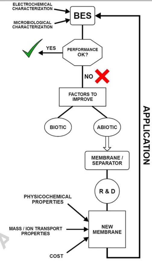
The process of BES development from the perspective of the membrane/separator can be presented by the schematic flow chart in Fig. 1 and particular cornerstones will be addressed to structure this paper. Hence, in the next sections, the most important membrane related areas will be analyzed, followed by the assessment of recent achievements with various classes of polymer-based membranes as separators in BES. We will try to give an insight by omitting/decreasing the amount of redundant information for individual studies from the type “Study A shows this, Study B found that”.
Rather, it will be aimed to make an objective discussion based tendencies. In our opinion, such an interpretation of the subject can enhance the readability, make the paper informative and of reasonable volume at the same time, which are standards for a timely literature survey.
7
Fig. 1 – Process flow chart of BES development from a membrane/separator point of view
8
2. Issues to tackle for a way forward – Assessment of most critical membrane separator properties in BES
2.1. High reactant (substrate, O2, CO2) mass transfer resistance – upstream point of view.
Substrates (normally organic matters) are fed to be purposefully consumed by electro-active strains, located in the anode chamber and/or in case of biocathodes, in the cathode chamber as well. Either way, if the transport of these components is not sufficiently restricted by the membrane, the substrate crossover diverts from appropriate metabolic utilization and consequently, the deterioration of BES performance can be expected i.e. in terms of product recovery per unit of substrate loaded [26]. Therefore, for a given substrate component (S), substrate mass transfer rate (kS) through the membrane is useful to determine (Section 3.) in order to get a picture about expectable losses, which may cause the limitation of biocatalytic reactions and induce side-reactions on the other electrode. The transfer of oxygen molecules towards the anode chamber can be a critical issue when MFCs are the objects of interest. Oxygen is supplied in MFCs to the cathode-side to form H2O via oxygen reduction reaction (ORR) at the electrode surface based on the utilization of oxygen from air (air-cathode MFCs) or dissolved oxygen from the cathode electrolyte (two-compartment MFCs) with the involvement of protons and electrons, liberated from biocatalytic substrate conversion taking place on
9
the anode-side. This latter, however, must be maintained under anaerobic conditions. Hence, penetration of dissolved oxygen gas to the anode should be prevented or otherwise, metabolic perturbation of exoelectrogens will occur, causing losses i.e. in CE, energy yield, etc. [21,26,27]. Carbon dioxide can be seen as a novel starting material to generate value-added commodities in bio- electrosynthesis cells [28]. Hence, similar to the case of (organic) substrates discussed above, escape of this substance (typically from the cathode to the anode chamber) through the membrane separator can be a technological issue. Methods concerning the experimental determination of mass transfer and diffusion coefficients (substrate, oxygen) for particular membranes can be found in the already published literature and will be detailed in Section 3.
2.2. High product (both for gaseous and liquid phase components) mass transfer resistance – downstream point of view.
In BES designed with a separator (such as in two-chamber applications) the products are typically generated on the cathode and can accumulate either in the gaseous (H2, CH4) or the liquid (organic acids, alcohols, H2O2, etc.) phase [7]. In both cases, losses of particular compounds due to migration through the membrane into the anode half-cell should be mitigated in order to assist the downstream process [29]. On grounds of similar considerations, the penetration of metabolic products released by bacteria in the anode
10
compartment (that might be carbon dioxide, methane, etc.) is also to be avoided so as to restrict contamination of products on the cathode-side and ease the recovery and purification of targeted substances [9]. In addition, transfer of cathode side products to the anode electrode can lead to undesired recycle mechanism, i.e. when H2 is converted by anode-respiring exoelectrogenic bacteria or by other (non-electro-active) H2-scavengers such as methanogens and homoacetogens, causing in such a way the deterioration of cathodic H2 recovery, H2 yield/productivity and the potential appearance of parasitic current (virtually enhancing the CE) [30,31]. Nonetheless, this challenge is more pronounced in membrane-less (single-chamber) BES constructions.
In general, water transport through the solid electrolyte (membrane) is a notable issue in the field of fuel cell technology [32]. In case of BES – most likely in case of MFCs equipped with membrane electrode assembly and air- cathode – the nature of water is also important. It is present in the electrolyte solution bridging the electrodes and the membrane and besides, as a product formed at the cathode [33]. Management of water transport can be challenging since air-cathodes require water for proper operation, however, the so-called cathode flooding can hinder oxygen transfer to the cathode as well as passivate the electrochemically active catalyst sites at cathode through their occupation by water molecules [34, 35]. It is to mention that water transport is not necessarily a negative factor, mainly if the potential of the technology is
11
considered from wastewater treatment point of view, according to Gajda et al.
[35].
From a water transfer mechanism viewpoint, it is to note that the ionic species moving through the separator can grab and carry water molecules by electroosmosis, which is a process (together with the occurring electro-osmotic drag) that can be recognized as a convective electrolyte flow through a charged material driven by the electric field present [36]. For its quantification, electro-osmotic drag coefficients can be derived, which shows the number of water molecules per charged species being transported (most commonly protons) [37].
2.3. High ionic conductivity (Low ion transfer resistance).
The internal resistance of BES is directly proportional to membrane separator conductivity, which will affect the actual electrochemical potential losses (i.e. on the cathode-side of MFCs). Hence, a membrane with smaller ohmic resistance is favored to establish an efficient process [38] and should be of hydrophilic character (to allow sufficient ion transport and mitigate internal resistance) [39]. It is noteworthy that besides the membrane as solid electrolyte, the conductivity of anolyte and catholyte as liquid electrolytes – which can be orders of magnitudes lower than that of the membrane (e.g.
wastewater vs. Nafion) [40] – should be also increased to reduce internal Ohmic losses [41]. As noted by Harnisch and Schröder [42], actual membrane
12
material (Ohmic) resistance can be highly dependent on the composition/concentration of liquid electrolyte solution. Actually, the internal resistance of BES involves (i) polarization/charge transfer resistances on the electrodes (anode, cathode) and (ii) Ohmic resistance of (liquid+solid) electrolytes. These particular contributions can be distinguished by techniques such as electrochemical impedance spectroscopy (EIS) [42,43]. As in many cases protons are the primary target ions to be shuttled between the anode and the cathode via the membrane, it can be worthy to quantify related mass transfer coefficients (and ion transport numbers for other charged species) – for instance as described by Zhang et al. [44] and Kondaveeti et al. [45] – and use them in BES characterization for a comprehensive assessment. These aspects will be elaborated later on in Section 3.
Moreover, it is to remark that proton flux across the membrane is not the only limiting factor in BES. As described by Torres et al. [46], protons must first be transported from an electrode surface where they are discharged (i.e.
anodic organic matter oxidation by electro-active microbes) and travel through a corresponding diffusional layer in order to reach the bulk (electrolyte solution) phase before continuing their movement via the membrane separator towards the counter electrode. Consequently, metabolite transfer between the electrode and the bulk solution can have an impact [47] and in particular, faster proton transfer between the electrodes and membrane would be beneficial to improve the bioelectrochemical process [48].
13
2.4. Sufficient geometrical traits (area, thickness, surface morphology) and stability over time.
As it was found, the membrane employed in BES i.e. in MFCs between the anode and cathode electrodes as spatial separator highly determines the obtainable performance i.e. in terms of power density [17]. This indicates a need of reporting process outputs relative to the actual membrane surface area. The importance of membrane size was recognized [49], where area may influence the capacity of exchanging ions i.e. protons between the half-cells and ultimately, the ion fluxes and corresponding transfer resistances [38].
Therefore, the ion-exchange capacity – meaning the number of functional groups (in molar equivalents) relative to the mass of membrane in case of polymeric, non-porous materials – is a substantial characteristic to be considered [50] and was found to directly affect microbial fuel cell efficiency [51]. Besides that fact that thickness inherently determines component diffusivities [52], it may require an optimization to find a trade-off value balancing between membrane resistance and cross-over effects [38,50].
Furthermore, wettability and membrane swelling are to be considered as altering factors of thickness over time, which may concurrently affect the mass transfer and internal resistance in BES.
Concerning membrane surface features, roughness seems to count, especially from the viewpoint of superficial bacterial growth and consequent biofouling. To counteract this disadvantageous phenomenon, smoother
14
membrane surfaces would be more beneficial [53]. In fact, the adhesion of bacteria onto the membrane (enhanced by the release of extracellular polymeric substances, salt precipitates on the membrane surface) and successive formation of biofilm layer are reportedly disadvantageous [54,55], for instance due to reduced ion exchange capacity, conductivity concomitantly increased transport resistance [56]. Thus, fouling (both chemical and biological) can be seen as a threat leading to insufficient BES operation, occurring mostly in longer-terms [57]. Additionally, as membrane separator properties are subject to change over time because of such microbial attachment, its stability might be influenced too and should therefore withstand biological degradation. This points to the need of monitoring separator characteristics not only in shorter-, but also in longer-term experiments [58]
and timely treatment to regenerate its properties may be necessary [59].
Besides, on the top of microbial impacts, membrane separators should resist against oxidative/reductive atmospheres, various chemical compounds found in BES, which are dependent on the particular application (such as microbial fuel and electrohydrogenesis cells) as well as the traits of the feedstock. This latter, in order to improve the energy/economical balances and the ecological footprint of the process, should be inexpensive, organic matter rich and environmental pollutant such as waste streams [60-66].
15
2.5. Potential to counteract pH-splitting
In bioelectrochemical systems, the cell electrode reactions take place at electrodes separated from each other by a membrane and (non-mixed) electrolytes in most cases. The catholyte consists many times of a buffer solution (i.e. phosphate-based) or alternatively, it is unbuffered. As the composition of the anode- and cathode-side electrolytes is generally different, inevitable concentration gradients arise on the two side of the membrane separator.
Theoretically, membranes should be selective to allow the passage of selected ions such as proton, while others are retained properly. However, in practice, it is a common observation that such a privileged mechanism cannot be accomplished. Rather, membranes tend to transfer other ions (mainly the ones present in regular wastewater-based anolyte, e. g. K+, Na+, Ca2+, Mg2+, NH4+, SO4-, Cl-) as well [67,68], which can be regarded as a charge-balancing ion flux [42], driving the system towards charge neutrality on the two opposite sides of the separator [69]. This process inherently depresses the migration of protons since a part of membrane capacity to exchange ions between the electrodes is occupied by other charged species [59]. As a result, protons – released by the activity of exoelectrogenic microorganisms transforming the substrates – cannot be carried away at as fast as they are supposed to be (imbalanced proton production and consumption rates) and will get accumulated in one of the compartments (e.g. in the anolyte of MFCs),
16
consecutively acidifying the electrode (anode) environment. Simultaneously, the pH in the counter (cathode) electrode compartment will get increased (due to the insufficient quantity of protons and the formation of alkaline hydroxides from cations transported and OH- present in the cathode chamber) and the pH gradient develops across the membrane, called the pH-splitting phenomenon [56,70].
While pH-splitting is mentioned generally as a negative side-effect in BES, it might be exploited to harvest some cathodic by-products. As a matter of fact, the alkaline solution (mostly sodium- and potassium-hydroxides, causing increased pH in the cathode chamber) drawn from the reactors could be regarded as a valuable commodity after putting minor efforts into the handling of these cathodic streams e. g. feeding of clean water [71]. The production of caustic in such a manner i.e. joint to the electricity generation may be seen as an opportunity to tackle the issue of pH-splitting and increase the economic footprint of the technology. Additionally, in cases when the cathode is to be protected from disadvantageous biofilm formation, the caustic solutions may be supportive because of their disinfectant/anti-microbial growth impact [72]. Besides, using potassium-rich waste streams and the formed caustic solution as sorbent, the sequestration of carbon dioxide in a form of bicarbonate salts could be a possibility, according to Gajda et al. [73,74].
It is to underline that the membrane type influences not only the direction of ion transfer, but the energy efficiency of the transfer, as well. As Sleutels et al. [75] demonstrated, cation and anion exchange membranes
17
(CEM and AEM, carrying negative and positive charge on their functional groups, respectively) show remarkable differences in terms of actual ionic flux (J), which can be described by the Nernst-Planck equation (Eq. 1):
(
) (1)
where D, C and z are the diffusivity, concentration and valence of the given (ionic) species, respectively, F is the Faraday’s constant, R is the universal gas constant, T is the absolute temperature and E is the electric field of the electrolyte through which the ions move. Therefore, the ion transport is determined by diffusion and migration processes, and when membrane-cross transport is discussed, the amount of energy dissipated or gained by the ion transfer is proportional to the membrane potential [75]. These membrane potentials (affected by the chemical potential of both the electrolyte solution and the ionic species in the solid electrolyte) are negative both for CEM and AEM. However, the ionic species migrating through them can be positive or negative, among which negatively charged ions are energetically preferred to be transferred across the separator relative to positive ions. This can point to a theoretical advantage of using AEMs in BESs in order to minimize ion transfer- related losses [75].
To maximize the efficiency of BES, large ion transfer losses and pH- splitting should be diminished. In BES, every unit of pH change across the
18
membrane provokes potential losses and in the end, the achievable efficiency [40]. Besides, aspects such as the survival of bacteria ought to be considered here, since, in general, strongly acidic circumstances (for an extended time) in the vicinity of biofilm-covered electrode surfaces are not optimal for electro- active strains, demonstrating preference to pH values closer to neutral [76].
3. Effective techniques for the characterization of membrane separators and related transport processes
3.1. Determination of essential physico-chemical membrane properties
From practical and material engineering viewpoints, studying the structure of physico-chemically homogenous/inhomogenous materials i.e.
individual polymers, blends and composites is essential. This may involve simulation methods [77], but the importance of experimental approaches e.g.
using various microscopic methods in membrane surface morphology and topology characterization is also beyond question. Among microscopy techniques, scanning electron microscopy (SEM) – and transmission electron microscopy (TEM) for studies needing higher resolution such as investigation of pore size and its distribution for porous membranes – and atomic force microscopy (AFM) are mentioned as the most versatile options [78,79].
19
SEM studies can be implemented for mapping the microstructure morphology of membrane material (including homo- and heterogeneous segments) through optical analysis of SEM photographs taken for the particular samples [80]. The application of electron microscopy techniques also offers a powerful tool for assessing membrane modification and deterioration effects on morphology, microstructure as well as pore structure [81]. Thus, SEM seems to be useful for qualitative evaluation. AFM is often used when in addition to morphology, surface topological features are also of interest [82]. By creating the representative 3D images of the samples, AFM can deliver information about surface homogeneity, roughness and adhesion behavior [82].
Wetting properties – often referred as hydrophobicity – of the membranes are determined usually by measuring the contact angle () between a drop of liquid and the actual membrane surface. High wettability is indicated by contact angles of << 90°, while hydrophobic membrane surfaces are characterized by >> 90° [83]. The various technical implementations in literature to determine membrane contact angle (for example measurements by using so-called goniometer, captive bubble method, tilting plate method, capillary bridge method, etc.) are generally based on Young’s equation and apply optical analysis [83,84].
As in many cases ion exchange membranes are used in bioelectrochemical systems, they need to be characterized from an ion exchange capacity point of view (in accordance with Section 2.). The
20
quantification of IEC is commonly a subject of experimental membrane characterization, where titration method is generally used by soaking the membranes in NaCl solution to replace protons with Na+ and then, the solution is titrated against NaOH to neutralize the amount of protons exchanged [85].
By knowing the dry membrane mass (m), the titrant volume (V) and its molar concentration (M), the IEC (e.g. in unit of mmol g-1) can be delivered (Eq. 2).
To determine the equivalent point of titration, phenolphthalein is well-accepted indicator [85].
(2)
Water uptake (denoted by ) is a helpful parameter to describe the average quantity of water molecules per the functional groups of the membrane at equilibrium [86]. Simple weight measurements can be carried out to obtain the dry and hydrates masses of the sample, md and mh, respectively, as well as the moisture content ( ). This is then specified to IEC and the molar mass of water (MW) to derive (Eq. 3) [86].
(3)
One of the significant performance-limiting phenomena in BES is the so- called fouling/biofouling, as emphasized in Section 2. During this process, the
21
active sites of the separator become covered by particles, solid matter, biological materials or microbe cells. As a standard technique, the examination of fouling can be performed by measuring the pressure drop across the separator [87]. To assess (bio)fouling via optical (visualization) techniques, the common microscopic techniques (as outlined above) are routinely applied, for example by SEM micrographs. For more in-depth analysis of (bio)fouling phenomena, Fourier transformation infrared spectroscopy (FTIR) could be a promising candidate, assisting the chemical identification of the membrane- attached materials (e.g. the amount of amino acid or polysaccharide fraction in the sample) [88].
3.2. Quantification of membrane-related mass transport and transfer rates
Following the transport of species through a given separator are useful for process monitoring and better understanding of what related mechanisms contribute to an actual BES performance.
For example, oxygen permeation towards the anode chamber can be a critical issue in microbial fuel cells as discussed previously (Section 2).
Usually, oxygen mass transfer and diffusion coefficients (kO and DO, respectively) are used to characterize the process. To measure these data, abiotic test rigs are preferred, based on the change of dissolved oxygen concentration over time in one side of the membrane while the other one is
22
filled with an O2 saturated liquid. The formula to compute kO is presented in Eq. 4 [52]:
[( )] (4)
where V is the liquid volume, A is the membrane surface, C0 and C are the dissolved oxygen concentrations in the saturated half-cell (representing the cathode) and in the opposite (anode) chamber at time t, respectively. To calculate DO, kO and membrane thickness (L) are required (Eq. 5).
(5)
On similar grounds, data for the substrate can be calculated as well. kS (the substrate mass transfer coefficient) takes into account (i) the initial substrate concentration in the anode chamber (CS,0) and its value at time t in the opposite chamber (CS) according to Eq. 6 [52].
[( )
] (6)
DS (substrate diffusivity) can be derived analogous to Eq. 5 from and membrane thickness (Eq. 7)
23
(7)
Ion mass transfer coefficient can be obtained for particular ionic species analogous to the balance equation in Eq. 6 by substituting the appropriate Ci concentrations [89]. Similar approach was communicated for proton mass transfer coefficient (kH) determination by Zhang et al. [44], where pH probe was used to monitor the changes in the anodic pH after adjusting it to 8.5 with sodium hydroxide solution (Eq. 8).
[( )
] (8)
where C1,0 and C2,0 are the initial concentrations of the chambers with neutral and elevated pH (considered as cathode and anode chambers), respectively, while C2 is the proton concentration in the anode solution at time t.
For characterization of water transport properties of membranes, several techniques can be adapted from literature [90]. The determination of diffusivity (DW) and interfacial mass transfer coefficient (kW,I) are based on the measurement of water uptake values ( ) of the membrane. The test device consists of two flow channels, where aqueous solution flows in one side (side A) of the separator, while oxygen gas flows on the other side (side B) [86]. The flow rate of water at the exit of side B channel can be quantified by using water traps and subsequent measurement of the amount of transported water
24
molecules. Afterwards, once DW and kW,I are known, it allows the computation of electro-osmotic drag coefficients [90].
3.3. Electrochemical impedance spectroscopy for studying membrane resistance and ionic/proton conductivity
Electrochemical impedance spectroscopy (EIS) is a tool for the assessment of certain BES traits i.e. associated with the membrane employed.
EIS has the capability for separating the different resistance-like parameters occurring in bioelectrochemical reactors such as anodic/cathodic charge transfer resistance, double-layer capacitance, mass transport resistance, electrolyte resistance [91,92]. When using EIS to study discrete electrodes or a whole BES cell, sinusoidal alternating perturbation is applied, generally with a small amplitude (10 mV or less) in order to (i) compare the disturbance and the electrode response by measuring phase shift and amplitude of current and voltage signals, (ii) prevent interference with the data acquisition and (iii) avoid biofilm deterioration when measurements are conducted in the presence of electro-active microbes forming biocatalyst film layer on the electrode surface [92]. The frequency interval of EIS measurements covers the range of 100 kHz – 1 mHz. The evaluation of the impedance results relies on equivalent circuit models (ECMs) and representation mainly in form of Nyquist (real impedance vs. imaginary impedance) and Bode (frequency vs. phase angle) plots.
Information about the fundamental theory of EIS and its use in BES are detailed elsewhere [93].
25
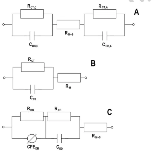
When membranes are the main target of EIS analysis, several experimental arrangements are available and accordingly to be able to reveal different membrane properties. For instance, the ohmic resistance of the membrane – as a part of the total ohmic resistance of a BES – can be easily determined in both biotic and abiotic systems by two-electrode experimental setup, where anode act as the working electrode and the cathode is used as both reference and counter electrodes [94]. In this case, a symmetric ECM can be used according to Fig. 2A. By conducting EIS analysis in the presence and absence of membrane separator – while maintaining uniform conditions in terms of other parameters – the total ohmic resistance (which contains electrolyte solution, membrane and other connection resistance) and the ohmic resistance without membrane resistance can be quantified [95]. The difference between the two values is the ohmic resistance of the membrane, which can be an indicator not only of the differences between various membranes but of the membrane-related changes appearing in long-term operation [96].
EIS offers an effective way for studying the transport phenomena of polymeric electrolyte membranes [97]. In traditional abiotic systems (e. g. PEM fuel cells), proton – and generally – ionic conductivity of the membrane samples can be determined both by two- or four-probe systems considering the high-frequency range (often as high as 105 – 106 Hz) of the EIS spectra (appearing usually as a semi-circle on the Nyquist plot) [98]. The proper choice of the measurements technique is suggested on the basis of real membrane
26
employment circumstances, e.g. the membrane is used in membrane electrode assembly or separates two liquid phase. In the first case, the two- probe, while in the latter case the four-probe method is widely used [99,100].
ECMs for these cases can be seen in Figs. 2B and C [101]. Once the membrane resistance and the geometry (in two-probe case, membrane thickness and electrode surface area, while in four-probe case, distance between reference electrodes and the membrane cross-sectional area are needed) of the given set-up are known, the conductivity (in unit of S cm-1) can be calculated.
Fig. 2 – Equivalent circuit models (ECMs) for electrochemical impedance spectroscopy (EIS) measurements. (A) Whole-cell ECM; (B) ECM for two-probe measurement; (C) ECM for four-probe measurement. Resistors, capacitors and constant phase element (non-ideal capacitance) are denoted as R, C and CPE, while
27
subscripts “C”, “A”, “M”, “S”, “CT”, “DB” and “ED” refer to the cathode, anode, membrane, solution, charge transfer, diffusion boundary layer and electrical double layer, respectively.
4. Polymers used for the preparation of negatively charged separators – cation exchange membranes (CEM)
In polymeric (electrolyte) materials to fabricate CEM, negatively-charged functional groups are linked to a backbone in order to accomplish cation transfer. The most recognized CEM in BES is Nafion (to be further sub-divided as explained by Oliot et al. [57], taken actually into account as an effective proton exchange membrane (PEM) and the primary reference for comparative evaluations [38,102-104]. PEMs, from the point of view of polymer material structures, can be classified perfluorinated, fluorinated, non-fluorinated, acid- base blend-based, etc. [105]. Among them, Nafion contains a poly(tetrafluoroethylene) (PTFE) backbone and proton-conducting sulfonic acid head-groups attached [41]. Though it demonstrates good mechanical/thermal stability as well as remarkable ionic conductivity [15], main shortcomings for bioelectrochemical applications include high price, inefficient selectivity of proton transport, notable O2 mass transfer and sensitivity to biofouling. To enhance Nafion properties, several attempts have been realized via its combination with other materials to manufacture special composite membranes [57,106] i.e. carbon nanocomposite/Nafion [107], PVA-Nafion-
28
borosilicate [19], Nafion with silica-based functionalized fillers [108], Nafion/PVDF nanofiber [109], etc.
Apart from that, efforts have been made to substitute Nafion and apply membranes that fit better with the demands in BES, both in economical and technological terms. The major directions in the literature point to the improvement of individual polymer properties, the development of polymer blends and fabrication of composites with polymer content.
In these research lines, results with SPEEK [103,110,111] are appealing, which has paramount chemical stability and lower costs in comparison with Nafion [112]. However, depending on the degree of sulfonation and IEC, it might be prone to marked hydration and swelling as well [113]. Besides, promising outcomes have been reported with the already commercialized CMI-7000 as an alternative to Nafion [114-120]. Furthermore, particular studies demonstrated the potential of PBI [77], SPPS [121], SLDPE [122], SPVDF [123], crosslinked and sulfonated PVA [124] for membrane manufacturing and application in BES. Moreover, blend membrane preparation has been investigated too, based on the mixture of polymers such as PVA-SA- PEG [125], SPEEK-PES [126], PES-SPES [127]. Additionally, specific incorporations of nanoparticles e.g. magnetite, graphene oxide with some of the polymers mentioned above were also communicated [128-130], however, these often produce porous membrane structures. Other possibilities regarding the application of polymer-composite materials in the bioelectrochemical field can be found in the review article published lately by Antolini [131].
29
The chemical structures of several representative polymers addressed herewith can be found in literature papers, such as Maiyalagan and Pasupathi [105] (Nafion), Zhao et al. [132] and Wei et al. [133] (SPEEK), Aeshala et al.
[134] (CMI-7000), Harsha et al. [135] (SPES), Schauer and Brozova, [136]
(SPPS). It can be noted that, for the functionalization of polymer backbones, negatively-charged sulfonate groups are the most preferred in CEM to transfer positively-charged counter-ions such as protons. In this aspect, it was observed that the increasing degree of sulfonation (e.g. in SPEEK) membranes can lead to better ion conductivity and MFC performance, however, a threshold level seems to exist and therefore, this factor should be optimized for an attractive operation [137].
5. Polymers used for the preparation of positively charged separators – anion exchange membranes (AEM)
In principles, the structure of AEM polymers is similar to CEM, except certainly that in this case, positively-charged functional groups are linked to the backbone in order to accomplish the transport of anions, where hydroxide ions (OH-) play a leading role in BES [138]. More or less a decade ago, it was shown in papers such as Kim et al. [52] and Rozendal et al. [139] that various bioelectrochemical applications, in particular MFC and MEC could be established and operated with commercialized AEMs (e.g. AEM-7001 and
30
Fumasep FAB) to replace the more traditionally used CEM and attain process enhancement.
As a matter of fact, among possible benefits of AEM over CEM (i.e.
Nafion) in BES, lower resistance, better buffering and restricted pH drop across the membrane are primarily mentioned. The latter property is related with restricted cation transport, while protons are still able to pass by linked to phosphate species (commonly found in electrolyte solutions used in BES), leading to reduced losses on the electrodes i.e. cathode [140]. However, in contrast to CEMs, AEMs could be more susceptible to substrate losses [141]
due to the easier crossover of negatively-charged acetate, butyrate, propionate, etc. These organic molecules are favored carbon-sources of exoelectrogenic bacteria and found in many feeds streams such as (waste water) effluents discharged by processes, such as dark fermentative hydrogen production and to some extent, anaerobic digestion [142-148].
So far, the experiences with AEMs in BES are less relative to CEM [23,106] and it is quite difficult to predict whether and AEM or CEM fits better with BES. This aspect, in agreement with the discussion above in Section 2, should be investigated case by case and a decision can be made accordingly.
Lately, Oliot et al. [57] listed particular AEMs tested in BES in particular MFCs.
Some of them are already offered on the market by several companies (Membrane International Inc., MEGA a.s., Tokuyama Co., Fumasep, Agfa, etc.) relying on (i) gel polystyrene cross linked with divinyl-benzene, (ii) polyester with poly-ethylene and poly(ether ether ketone), polysulphone, etc.
31
and mostly, quaternary ammonium group as charge-carrier functional group.
One of the issues to address could be the stability and deformation of AEMs in longer-terms [141], i.e. in case of materials such as AEM reinforced with PVC [140]. Recently, the topic of using AEM in electrochemical applications has been comprehensively reviewed by Varcoe et al. [50] and possible directions/strategies in AEM polymer chemistry and improvement were presented.
6. Size-selective, porous membranes based on polymers
The approach of porous membrane employment in BES relies either on the adaptation of polymeric filters well-known in water treatment technology, differing in pore diameter range i.e. micro-, ultra-, etc. [15] or coarse-pore materials, including a range of fabrics, fibers, meshes. As analyzed by Li et al.
[70], in both cases, economical saving can be realized (compared to Nafion for instance) and high ion permeability is normally observed, which decreases the treat of pH splitting [39]. On the one hand, these features are advantageous from an internal resistance and current density point of view [53]. However, at the same time, the open pore structure allows considerable mass transport i.e.
in terms of substrate and O2 (in MFCs), encoding for suboptimal performance i.e. when CE is considered [149]. In short, this can be described by the confrontation of ion and mass permeation [56]. Furthermore, it is known from the practice that porous membrane filters are highly sensitive to biofouling over
32
time, having an adverse effect on membrane stability and causes the substantial increment of membrane resistance [53]. Additionally, if the pore size is not rejective to the microorganisms, electrode (cathode) fouling may occur. In case of such an envisaged biofilm layer formation, ion transport limitations in the vicinity of cathode can be expected. For instance, protons can be hindered in reaching the electrode surface to react with electrons and active-sites of cathodic-side catalysts (i.e. Pt) may be deactivated too.
Therefore, porous materials seem to be more limiting than useful for BES [53].
Nevertheless, with appropriate modifications and functionalization of porous polymers, gates may be open to obtain membrane separators with improved properties.
On particular research line that has just recently emerged is associated with the application of ionic liquids (ILs). ILs are widely-known as attractive materials in a broad range of chemical and biotechnological processes and are salts composed of organic cations and organic/inorganic anions. By alternating these ion pairs, IL properties can be adjusted in accordance with actual requirements. Moreover, ILs are chemically/thermally stable, have non- detectable vapor pressure and many of them are liquids at room temperature.
Because of such attributes, they have attracted remarkable attention and been employed to improve separation techniques designed with membranes.
For instance, ILs have experimentally confirmed potential to construct novel electrodes, both anode and cathode resulting in enhanced MFC efficiency [150,151]. Apart from electrode design, several distinct ways appear
33
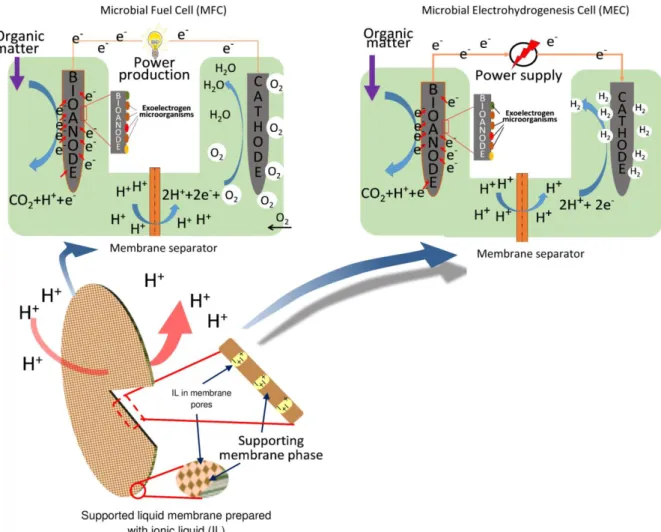
to apply ILs in fabrication of membranes for BES. One is the immobilization of ILs in high-porosity polymer membranes – such as PVDF [26,152] nylon [115]
– serving as a support matrix (Fig. 3). As a result, the conventional porous membranes can be turned into non-porous ones, in which ionic (charged) species (anion and cation of IL, to be considered as a salt-type chemical) are located. Successful demonstration of such so-called supported ionic liquid membranes (SILMs) can be found in papers by Hernández-Fernández et al.
[115] and Koók et al. [26,152].
Fig. 3 – Scheme of microbial fuel cell and microbial electrohydrogenesis cell systems highlighting the application of supported ionic liquid membrane as separator
34
For SILMs, the stability could be a concern but for now, not much relevant feedback gained in BES applications is available. To design and fabricate SILMs with sufficient working life, the porous support and the actual IL should be applied in a feasible combination as the interactions between these two phases in contact and their properties will determine the capillary binding forces [153], as crucial factor of SILM robustness. In the literature, specific works such as those conducted by Fortunato et al. [154,155] have reported information relevant to the durability of some SILMs under varied operating conditions.
Apart from SILMs, additional examples [156-158] have pointed to the use of ILs in the formulation of ionic liquid-polymer inclusion membranes and membrane-cathode assembly prepared with ILs. Furthermore, ILs could be employed together with Nafion to enhance proton conductivity of the membrane in MFCs [159]. Besides, PVA polyelectrolyte membranes containing ILs have been reported [160], leading to the significant increase of MFC performance.
7. Future outlook for possible membrane separator development in BES – Specific analysis and implications for Microbial Fuel Cells
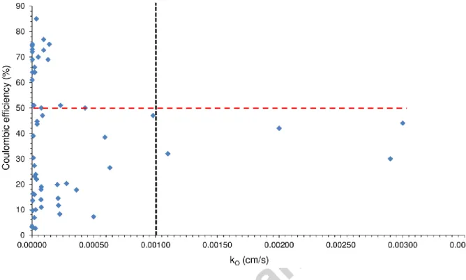
In Fig. 4, CE as a function of oxygen mass transfer coefficient (kO) measured in various physical separators/membranes throughout the MFC literature is shown. The CE expresses the actual ratio of electrons captured by
35
the anode and transferred subsequently towards the cathode relative to the total amount of electrons released from substrate degradation). Thus, it is a representative parameter to evaluate how efficiently a BES i.e. MFC works [2].
Fig. 4 – Coulombic efficiency data collected from literature as a function of oxygen mass transfer coefficient for various types of membranes/separators. Vertical dashed
line: critical kO; Horizontal dashed line: ≥ 50 % CE
In fact, the illustration in Fig. 4 includes data (taken from Table 1) for different porous/non-porous, charged/uncharged i.e. CEM/AEM, polymeric/non-polymeric, etc. membranes/separators such as applied in both two- and single-chamber devices. Basically, the users could expect higher CE values with membranes/separators demonstrating lower kO because of reasons elaborated in Section 2. However, this chart (based on a good mass literature data, n (number of data)=58 in Table 1) indicates that MFCs assembled with membranes/separators of nearly identical kO resulted in CEs
36
scattering on wide range, from only a few percent (<10 %) to around 70-90 % (Fig. 4). Consequently, though membrane properties should be enhanced to the best possible in terms of kO, it could be concluded that those alone cannot guarantee the adequate performance in BES.
Nevertheless, in the aspect, it would appear that membranes/separators demonstrating kO < 10-3 might in general be more feasible for MFCs, since almost exclusively in this critical window (vertical dashed line in Fig. 4) we are able to find CEs qualifying to the promising range of ≥ 50 % (horizontal dashed line in Fig. 4).
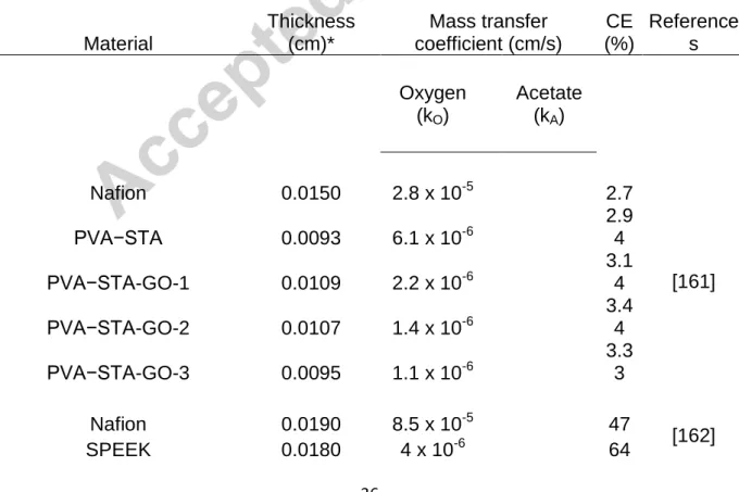
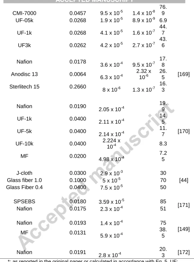
Table 1 – Coulombic efficiency (CE) literature data as a function of oxygen and substrate (acetate) mass transfer coefficients as well as thicknesses for a wide range of physical separators/membranes
Material
Thickness (cm)*
Mass transfer coefficient (cm/s)
CE (%)
Reference s
Oxygen (kO)
Acetate
(kA)
Nafion 0.0150 2.8 x 10⁻⁵ 2.7
[161]
PVA−STA 0.0093 6.1 x 10⁻⁶
2.9 4 PVA−STA-GO-1 0.0109 2.2 x 10⁻⁶
3.1 4 PVA−STA-GO-2 0.0107 1.4 x 10⁻⁶
3.4 4 PVA−STA-GO-3 0.0095 1.1 x 10⁻⁶
3.3 3
Nafion 0.0190 8.5 x 10⁻⁵ 47
[162]
SPEEK 0.0180 4 x 10⁻⁶ 64
37
SPEEK-TiO2-1 0.0170 3.2 x 10⁻⁶ 69 SPEEK-TiO2-2 0.0170 2.8 x 10⁻⁶ 72 SPEEK-TiO2-3 0.0180 2.2 x 10⁻⁶
74.
5 SPEEK-TiO2-4 0.0190 2.6 x 10⁻⁶ 73
QAPVA-TiO2 0.0040 5 x 10⁻⁶
13.
6 [163]
Nafion 0.0183 3 x 10⁻⁵ 10
LeHoAM-III 0.0220 5 x 10⁻⁶ 9.7
Nafion 0.0187 7.5 x 10⁻⁵ 19
[164]
CMI-7000 0.0450 2 x 10⁻⁵ 16
PP 80 0.0486 3.7 x 10⁻⁵ 22
PP 100 0.0507 7.3 x 10⁻⁵ 18
PPS 0.0520 7.5 x 10⁻⁵ 11
S-PPS 0.0514 7.2 x 10⁻⁵ 14
Q-PEEK 0.000002 2.1 x 10⁻⁵ 4.6 x 10⁻⁸ 66
[165]
AMI-7001 0.0045 1.03 x 10⁻⁵ 5.2 x 10⁻⁸ 51
QPEI 0.0003 2.3 x 10⁻⁵ 4 x 10⁻⁸ 64
[166]
AMI-7001 0.0045 1 x 10⁻⁶ 4.7 x 10⁻⁸ 61
SPEEK 0.0200 2.4 x 10⁻⁶ 75
[167]
Nafion 0.0188 1.6 x 10⁻⁵ 51
Natural clay-
Montmorillonite-1 0.2736 2.96 x 10⁻⁵
3.23 x 10⁻⁵
23.
9
[168]
Natural clay-
Montmorillonite-2 0.5005 1.94 x 10⁻⁵ 2.6 x 10⁻⁵ 27.
3 Natural clay-
Montmorillonite-3 0.3991 1.09 x 10⁻⁵
2.38 x 10⁻⁵
30.
4 Natural clay-Kaolinite 0.3966 2.05 x 10⁻⁵
2.93 x 10⁻⁵
23.
1
Nafion 0.0191 4.3 x 10⁻⁴ 50
[45]
CEM 0.0002 9.8 x 10⁻⁴ 47
CMI-7000 0.9800 1 x 10⁻⁵ 39
PP 80 0.0010 3 x 10⁻³ 44
PP 100 0.0045 2 x 10⁻³ 42
Cellulose-ester 0.0014 1.1 x 10⁻³ 32
AMI-7001 0.0457 9.4 x 10⁻⁵ 5.5 x 10⁻⁸ 72.
7 [52]
Nafion 0.0185 1.3 x 10⁻⁴ 5.3 x 10⁻⁸ 69
38
CMI-7000 0.0457 9.5 x 10⁻⁵ 1.4 x 10⁻⁸ 76.
9 UF-05k 0.0268 1.9 x 10⁻⁵ 8.9 x 10⁻⁹ 6.9
UF-1k 0.0268 4.1 x 10⁻⁵ 1.6 x 10⁻⁷ 44.
7 UF3k 0.0262 4.2 x 10⁻⁵ 2.7 x 10⁻⁷
43.
6
Nafion 0.0178
3.6 x 10⁻⁴ 9.5 x 10⁻⁷ 17.
8
[169]
Anodisc 13 0.0064
6.3 x 10⁻⁴
2.32 x 10⁻⁶
26.
5 Sterlitech 15 0.2660
8 x 10⁻⁶ 1.3 x 10⁻⁷ 16.
3
Nafion 0.0190
2.05 x 10⁻⁴
19.
9
[170]
UF-1k 0.0400
2.11 x 10⁻⁴
14.
5
UF-5k 0.0400
2.14 x 10⁻⁴
11.
7
UF-10k 0.0400 2.224 x
10-4 8.3
MF 0.0200
4.98 x 10⁻⁴
7.2 5
J-cloth 0.0300 2.9 x 10⁻³ 30
[44]
Glass fiber 1.0 0.1000 5 x 10⁻⁵ 70
Glass Fiber 0.4 0.0400 7.5 x 10⁻⁵ 50
SPSEBS 0.0180 3.59 x 10⁻⁵ 85
[171]
Nafion 0.0175 2.3 x 10⁻⁴ 51
Nafion 0.0193 1.4 x 10⁻⁴ 75
[149]
MF 0.0131
5.9 x 10⁻⁴
38.
5
Nafion 0.0191
2.8 x 10⁻⁴
20.
3 [172]
*: as reported in the original paper or calculated in accordance with Eq. 5. UF:
ultrafiltration membrane, MF: microfiltration membrane
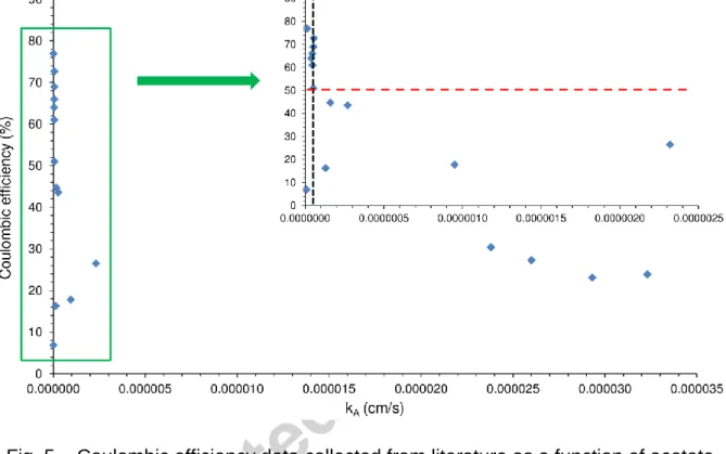
On similar grounds, considering relevant data available (n=17, Table 1), it can be argued that membranes/separators characterized with kA (mass
39
transfer coefficient for acetate, a commonly used substrate for fundamental investigations) in the order of 10-8 and below may be more beneficial to realize process enhancement (CE ≥ 50 %) in BES such as MFCs (Fig. 5 and its inset). Nonetheless, revisit of these aspects can be suggested over time once even more data are generated as a result of the expansion of the field.
Fig. 5 – Coulombic efficiency data collected from literature as a function of acetate mass transfer coefficient for various types of membranes/separators. Inset: data points below kA = 3x 10⁻⁶ cm s-1. Vertical dashed line: critical kA; Horizontal dashed
line: ≥ 50 % CE
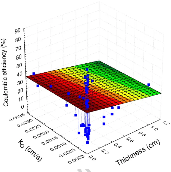
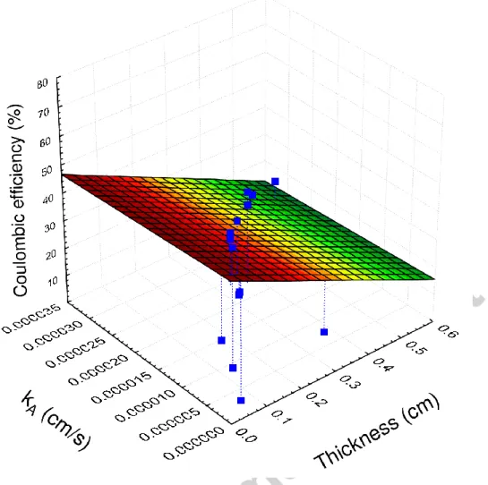
Additionally, Figs. 6 and 7 (linked to kO, kA and thickness data listed in Table 1) illuminate that thinner membranes/separators are more appealing to target higher CE values in MFC applications and verify the considerable impact of this feature, in agreement with the implications made in Section 2.
40
Fig. 6 – Coulombic efficiency data collected from literature as a function of oxygen mass transfer coefficient and thickness for various types of membranes/separators
41
Fig. 7 – Coulombic efficiency data collected from literature as a function of acetate mass transfer coefficient and thickness for various types of membranes/separators
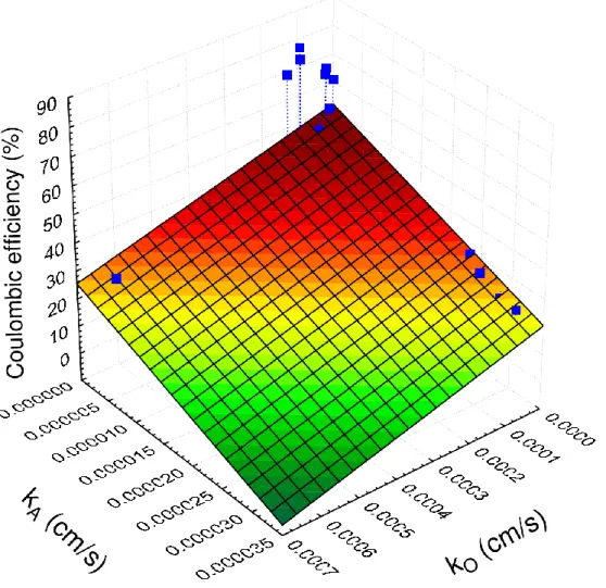
Moreover, membranes/separators are not only suggested to have kO and kA below the (roughly) estimated threshold levels (< 10-3 and ≤ 10-8, respectively), but these parameters ought to approach a minimum, according to the plot in Fig. 8, where it is to note that lower kO and kA could potentially aid the enhancement of CE (n=17, Table 1, where both kO and kA are available).
This coincides well with the evaluation provided in Section 2 concerning the most important traits that membranes/separators are supposed to reflect.
42
In summary, under such combination of membrane qualities (in particular smaller thickness and lower mass transfer coefficients), smaller component i.e. oxygen and substrate (acetate) diffusivities (DO, DS) can be expected (by taking Eqs. 5 and 7 into account), which are desirable to cut transport-related losses in BES. However, it is also noteworthy from a practical viewpoint that very thin membranes may cause difficulties with handling/mechanical durability and thus, such aspects should be also taken into account for adequate membrane engineering.
Fig. 8 – Coulombic efficiency data collected from literature as a function of oxygen and acetate mass transfer coefficient for various types of membranes/separators
43
8. A brief outlook on emerging bioelectrochemical processes utilizing membrane separators
As surveyed by Wang and Ren [173] and more lately by Zhen et al. [7], bioelectrochemical systems represent a versatile and suitable platform for the design of advanced, membrane-dependent processes accomplishing simultaneous waste treatment and electricity/electro-fuels production. Among such emerging and most recently introduced concepts, Microbial Desalination Cells (MDC) [174], Microbial Reverse-Electrodialysis Electrolysis Cells (MREC) [175] and Osmotic Microbial Electrochemical Cells (OMEC) [176] are the most particular ones to mention.
In MDC, the primary objective is to pull out electrical energy from certain (organic) feedstock by the aid of electro-active bacteria and use it to achieve saline (waste) water desalination [177-179]. Actually, MDC can be recognized as modified, next-generation system originating from microbial fuel cells, which, by inserting a couple of ion exchange membranes (i.e. CEM and AEM) between the anode- and cathode compartments, create a central chamber where salt removal takes place. As a result of MDC evolution, in accordance with the careful review of Sevda et al. [180], hybrid-MDC systems producing valuable chemicals such as H2 and other MDC-related technologies have been developed. The MREC has been demonstrated as an option for energy- efficient, sustainable generation of value-added substances (i.e. H2) [175], which captures and utilizes the electrical power coming from the conversion of organic matter by exoelectrogenic microorganisms as well as from saline
44
gradient arising in the reverse electrodialysis process using ion exchange membranes [181]. The OMEC can be constructed e.g. by deploying forward osmosis (FO) membranes in MFCs [182-184]. In OMEC, on the top of the benefits realized with conventional MFCs, reclamation of water from aqueous streams such as wastewaters is possible, as H2O (in agreement with the principles of FO) passes selectively from one electrode compartment to the other [185]. Besides, by the attachment of OMEC to other bioreactors, special membrane bioreactors can be established, possessing significant operating advantages in comparison to conventional systems [186-188].
9. Final conclusions and take home messages related to membrane separators in BES
Economic viability and low cost materials
For now, remarkable barriers for a range of bioelectrochemical applications, especially at an envisaged larger-scale can be identified [14,41,68]. From an economical point of view, membranes should be affordable. Relevant estimations for various materials can be found in the paper of Dhar and Lee [15] and it can be drawn that further efforts have to be invested to attain the reduction of costs [18]. In this aspects, apart from artificially designed and synthetized polymers, naturally-occurring polymers and relatively cheap materials such as cotton fabric combined with PVA-PVDF [189], gelatin and alginate [190], agar [191], rubber [192], biodegradable bag